Week 12- Final project
DEVELOPMENT OF DOOR TRIM PANEL
Automotive Plastic Trim:
The design of Automotive Interior and Exterior plastic components is called Trim. The plastic components that you see inside the car are Interior, Ex:- Dashboard, Instrument Panels, Doors, seating, and pillars. Plastic Components that you see outside of a car are the Exterior, Ex:- Bumpers, lighting, and Hood.
Door Trim:-
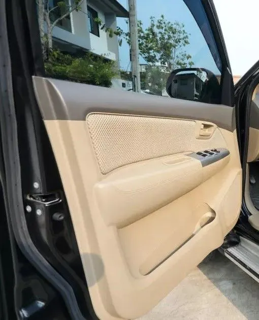
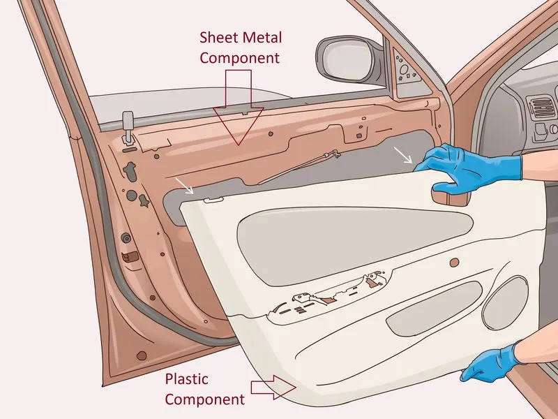
The door panel covers internal parts like the window regulator, the power window motor, and the wiring. It is attached to the sheet metal part of the door. It is designed differently based on the design of the sheet metal part of the door. Besides its aesthetic look, it also has functional features attached to it such as an armrest, bottle holder, speaker, attachment, etc. In older vehicles, door panels used to be made of cardboard and upholstered with material that matches the rest of the upholstery within the cabin. On the other hand, most modern cars have door panels made of plastic. The main materials used include kenaf, which grows year-round and has excellent CO2-absorbing properties, and plant-derived plastic, making them environmentally friendly as well.
Aim:-
To Design a Car door Plastic components placed in the car door panel by following the design standards used in the industries. The Reference Designs for the the Mechanical designing team of the Plastic components are drawn initially by the Class A surface defined by the concept Sketch team as well as by the Styling Class A using Alias Software and about Class A, the part body with thickness is designed by the Designing Team.
Abstract:-
The project report deals with the steps and procedures followed while developing plastic trims for car doors from a class A surface provided, using a CATIA V5 surface workbench. It explains the method I followed for creating the main tooling axis, side core axis, Class B surface, Class C surface, and final closed body creations. It also explains the draft analysis performed to check the manufacturability of the products using injection molding. Various plastic door trims such as map pockets, armrests, lower substrates, etc were successfully developed in the project.
Problem Statement:-
- Create a closed body of the door trim panel using the Class A surface provided along with the master section.
- Create a push pin with the dog house for the lower substrate.
- Use Heat Stakes for the part to the part attachment.
Tools Used:-
Part Workbench:
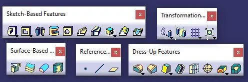
Surface Workbench:

Given:-
Class A Surface:-
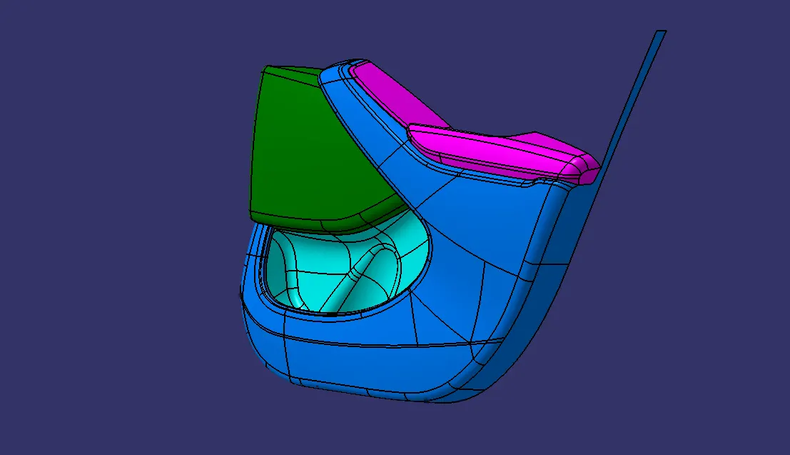
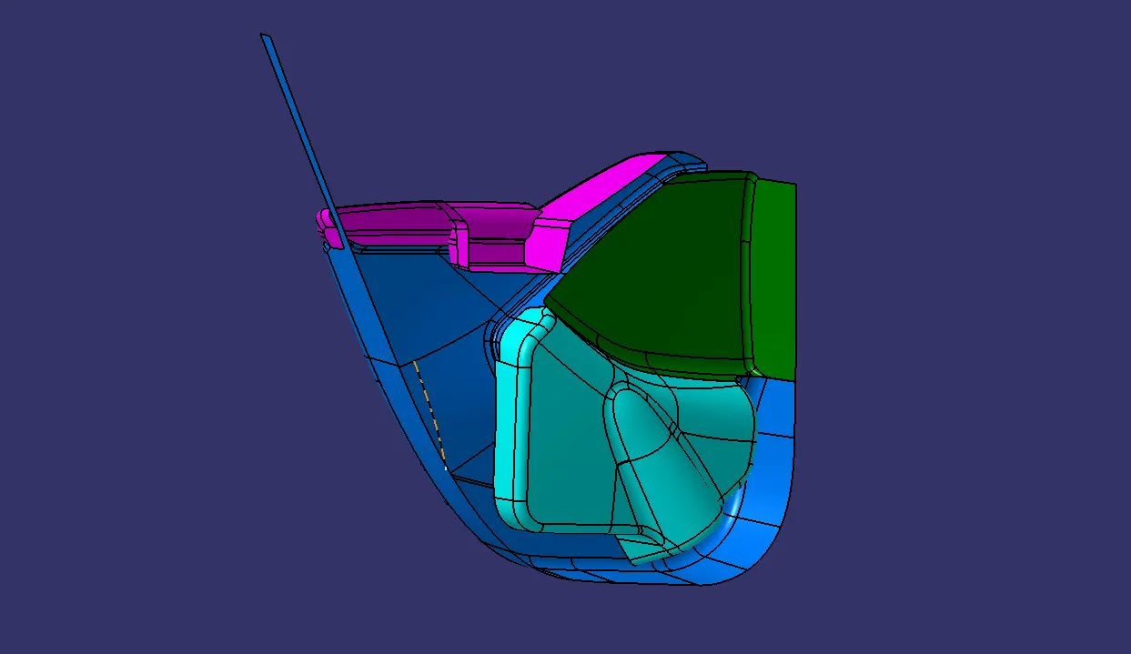
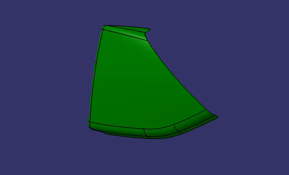
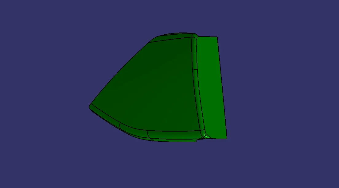
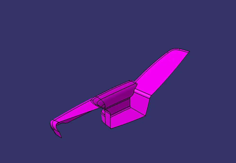
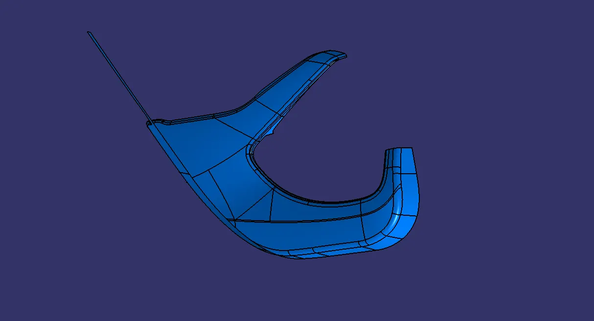
In the Automotive industry, there will be a dedicated team that will perform the aesthetic designing of various components including the whole vehicle. They will create various concept sketches after ideation. After that, they will also create a Class A surface of the product. This Class A surface is then passed over to the NPD CAD team. They will initially inspect the Class A surface in order to check if the design is manufacturable or if it is following the engineering principles. If there are any issues with the design, they will contact the product design team and will ask to modify the Class A surface in order to solve the problem. Here I received the Class A surface as shown below.
MAP POCKET:
ARM REST:
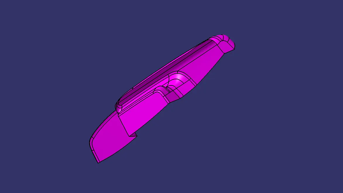
WATER BOTTLE HOLDER:
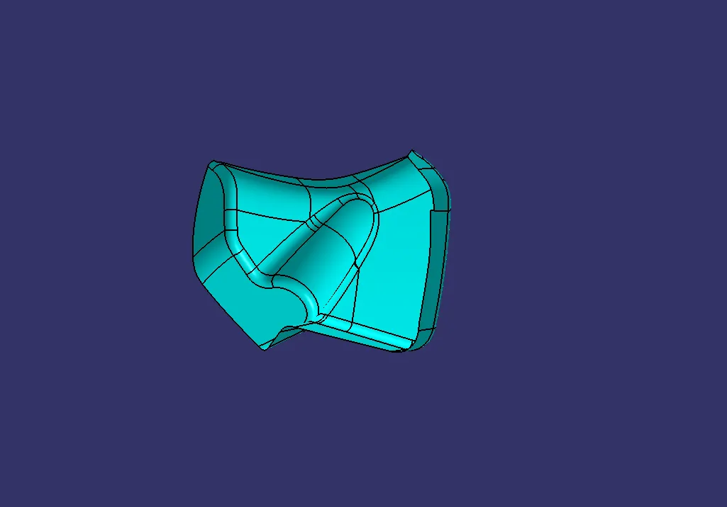
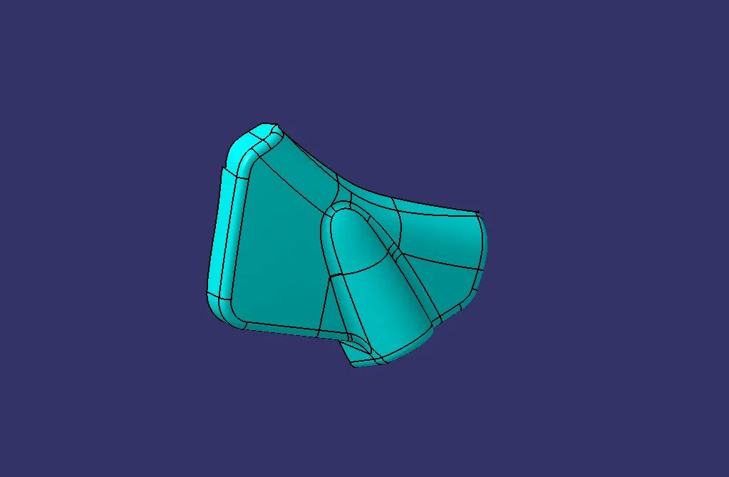
LOWER SUBSTRATE:
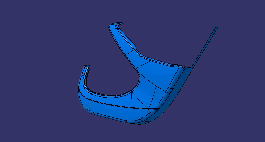
MASTER SECTION:
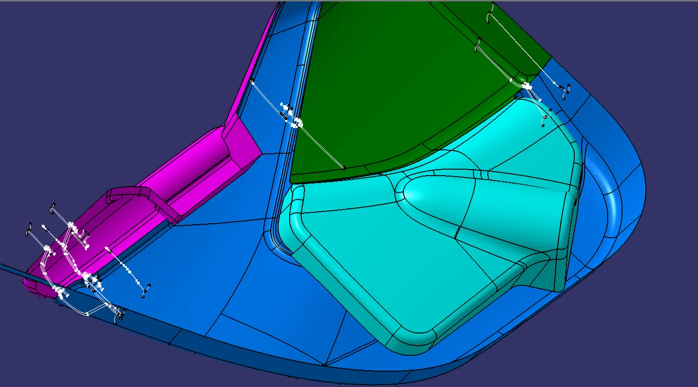
These are the guidelines provided to a design engineer which describe how a component would/must look like once it is modeled into a solid component from the class A surface. For example, in this model, we have received a master section as an input which tells us about the thickness of the component and dimensions and type of the engineering features on the component.
The sequence of Operation:-
- Creation of Tooling Axis and Draft analysis for A-surface.
- Creating B&C surface and Draft Analysis.
- Creating attachment features on the B-side and Draft Analysis.
Procedure:-
Tooling Axis Creation:-
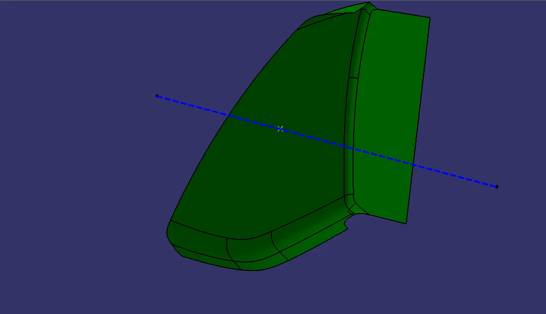
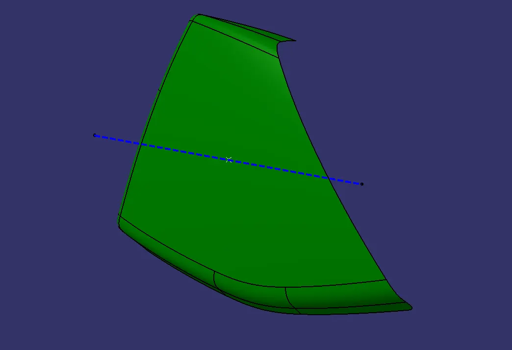
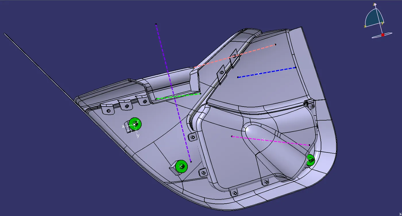
The main tooling axis was created by applying zero distance value on the Class A surface as shown below:-
MAP POCKET TOOLING AXIS:-
ARM REST TOOLING AXIS:-
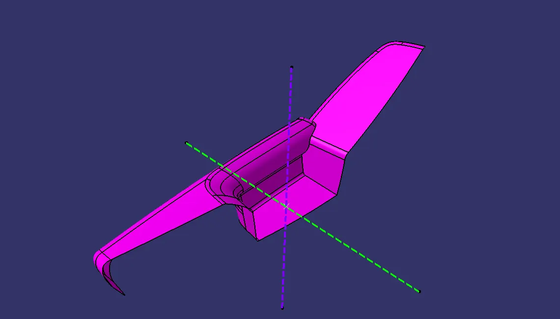
BOTTLE HOLDER TOOLING AXIS:-
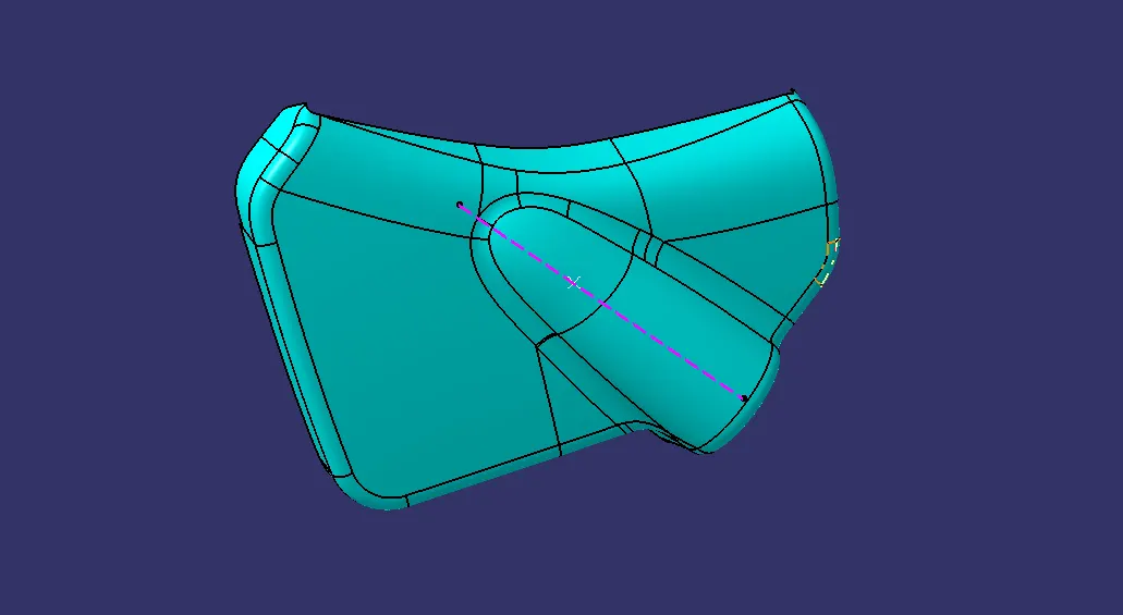
LOWER SUBSTRATE TOOLING AXIS:-
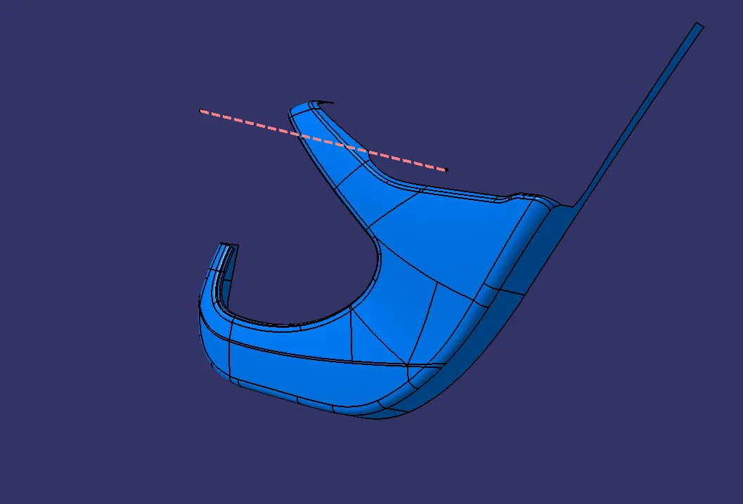
Draft Analysis:-
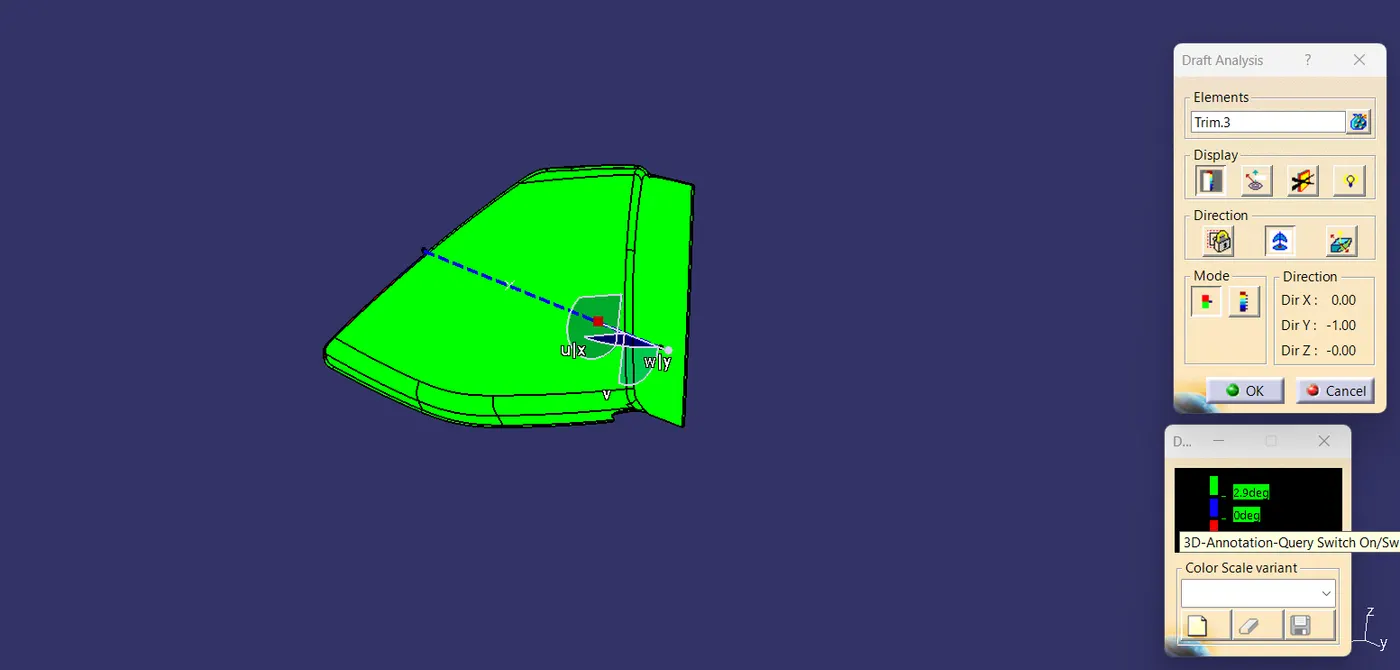
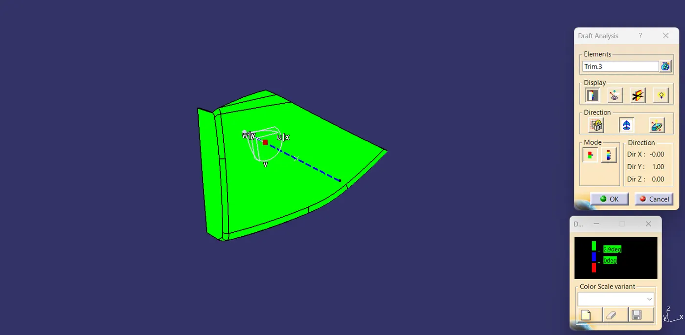
The draft analysis commands enables you to detect if the part you drafted will be easily removed. This type of analysis is performed based on color ranges identifying zones on the analyzed element where the deviation from the draft driection at any point, corresponds to specifies value.
This type of analysis is performed based on color ranges identifying zones on the analyzed element where the deviation from the draft direction at any point, corresponds to specified values.
These values are expressed in the unit as specified in tools>option>general>parameters>unit tab.
You can modify them by clicking on their corresponding arrow or by entering a value directly in the field.
The mapping texture accuracy depends of the video card used. Therefore, colors displayed on surfaces could be wrong according to the color scale, when the value displayed on the fly is right because the analysis is recomputed at the cursor location.
Sometimes, in the case of extremely closed values, it is recommended to switch to the quick mode to improve the color display accuracy.
The maximal draft analysis accuracy is 0.01 deg. According to the graphic card performance, this accuracy can be debased.
The different mapping analyses of the same surfaces cannot be displayed simultaneously, even if you have set the mapping analyses in no-show. You need to visualize them one after the other.
PROCEDURE TO PERFORM DRAFT ANALYSIS
1. Select a surface
2. Click the (feature) draft analysis icon.
3. Double-click on the value in the color scale to display the value edition dialog box.
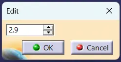
a) Enter a new value to redefine the color scale, or use the slider to position the distance value within the allowed range, and click OK.
b) The value is then frozen, and displayed in a green rectangle.
c) The color scaling settings (colors and graduated values) are saved when exiting the command, meaning the same settings will be applied when you edit a draft analysis. New settings are created with each new draft analysis.
d) When the draft angle value of the surface is equal or smaller than a graduated value, the color below the graduated value is applied.
e) When the draft angle value of the surface is greater than the greatest graduated value, the color above this graduated value is applied.
4. Exit the dialog box.
5. Click the light effect button and the colors of the analyzed elements react to the light source.
6. Click the inverse button to automatically reverse the draft direction.
7. Once you have finished analyzing the surface, click OK in the draft.
a) Note that settings are saved when exiting the command, and redisplayed when you select the draft analysis icon again.
b) Be careful, when selecting the direction, not to deselect the analyzed element.
c) A draft analysis can be performed just as well on a set of surfaces.
d) If an element belongs to an analysis, it cannot be selected simultaneously for another analysis, you need to remove the current analysis by deselecting the element to be able to use it again.
e) In some cases, even though the rendering style is properly set, it may happen that the analysis results are not visible. Check that the geometry is up-to-date, or perform an update on the involved geometric elements.
f) The analysis results depend on the current object. May you want to change the scope of analysis, use the Define in work object contextual command.
MAP POCKET DRAFT ANALYSIS:-
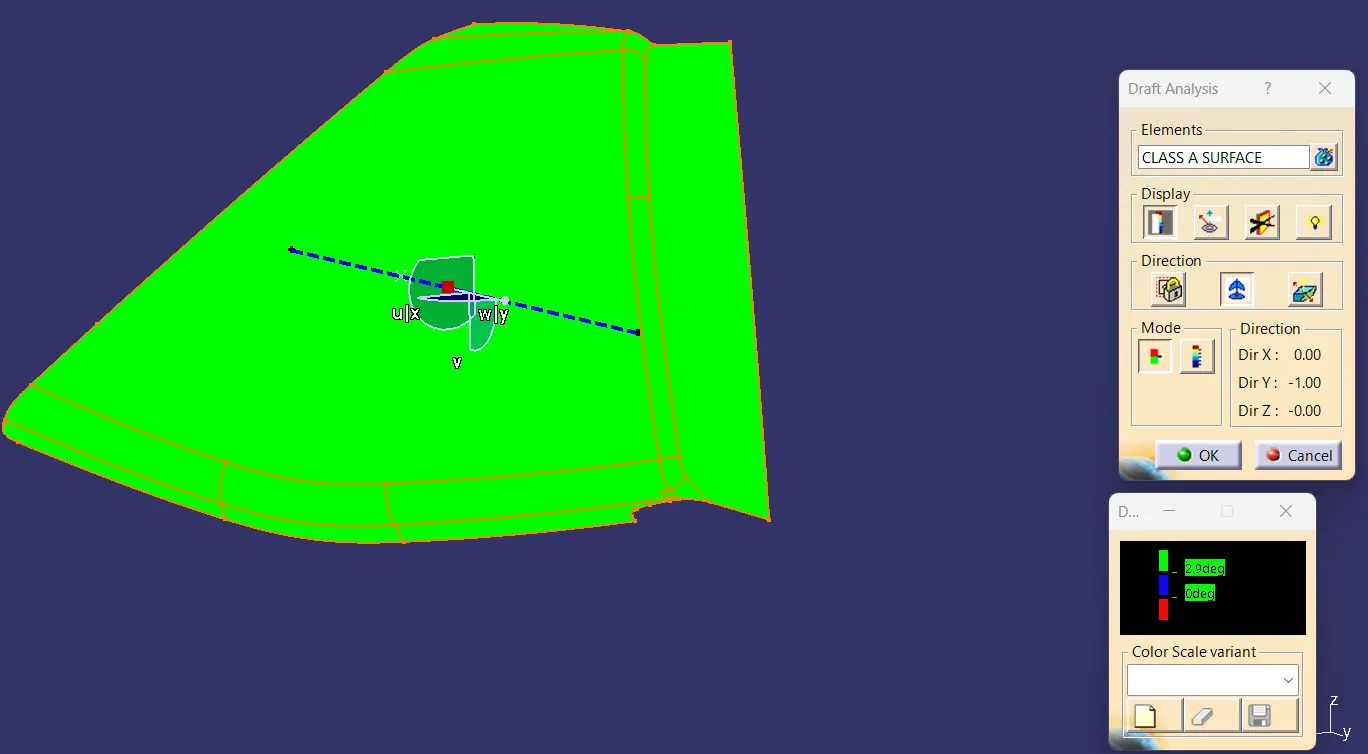
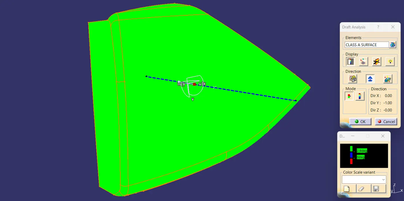
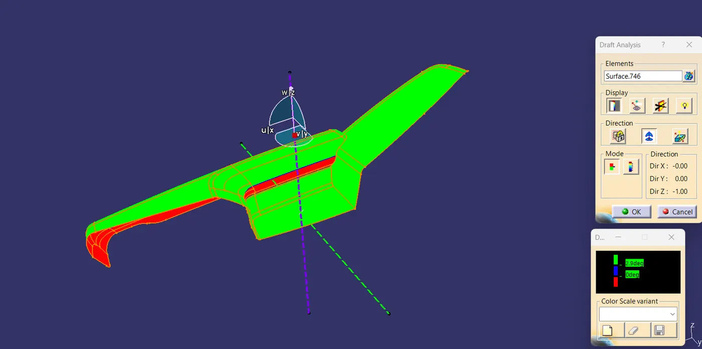
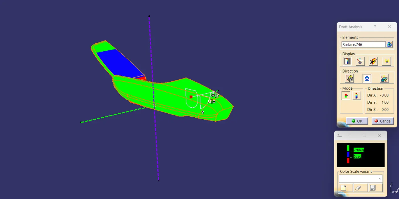
ARM REST DRFAT ANALYSIS:-
BOTTLE HOLDER DRAFT ANALYSIS:-
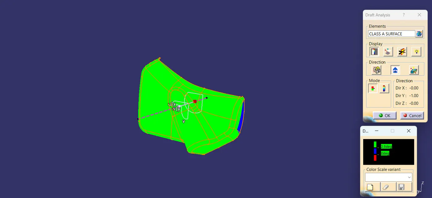
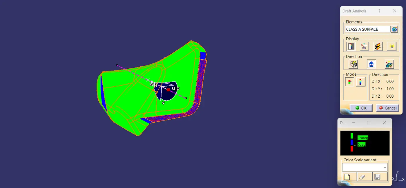
LOWER SUBSTRATE DRAFT ANALYSIS:-
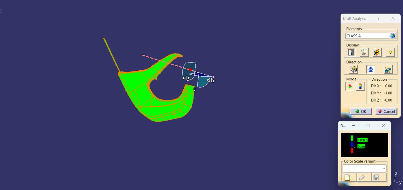
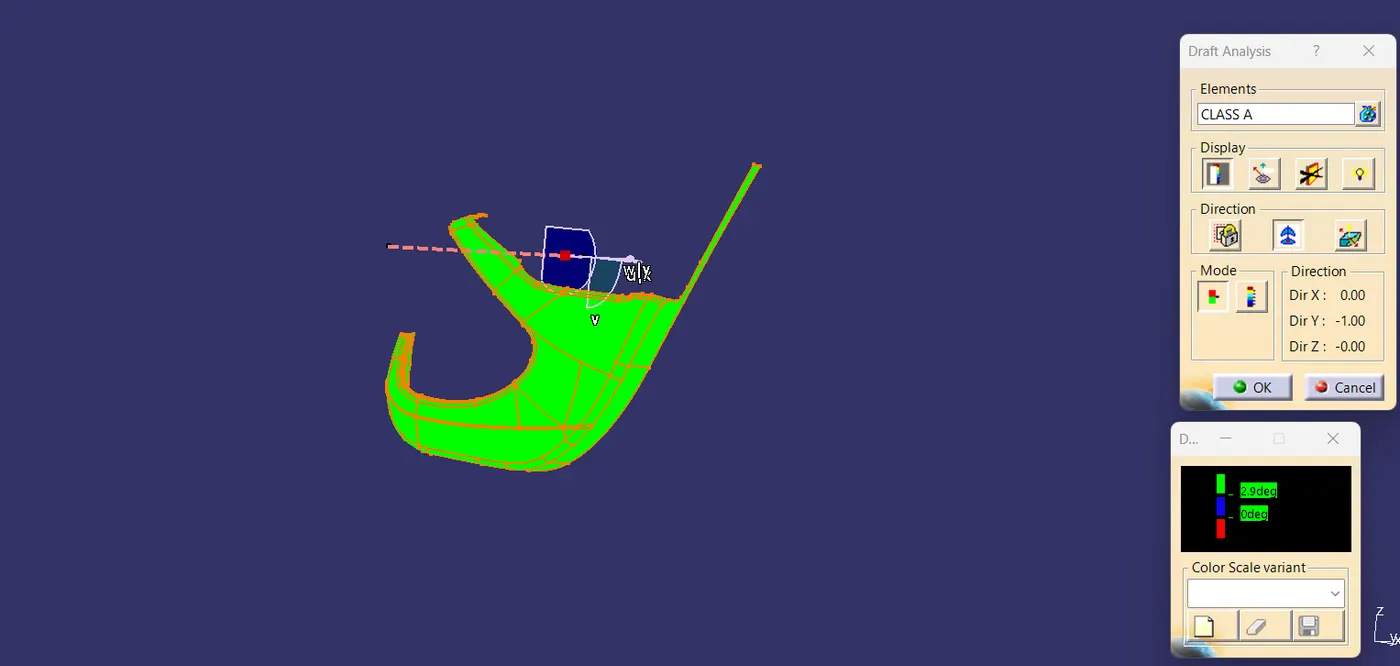
CREATING B&C SURFACE FOR EVERY COMPONENT:-
1. MAP POCKET:-
First, offset the A-surface for 2.5 mm(according to the master section) and work on the patches if any are required. Fillets were applied after necessary calculations.
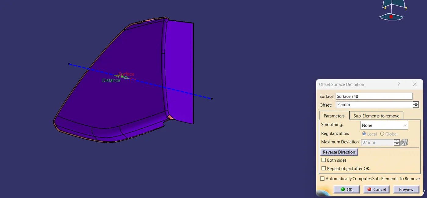
In purple color, it's the offset Class B surface.
Class C surface was swept along the boundary of Class A using the"sweep" option at an angle of 3 degrees outwards with respect to tooling direction. In some areas, the 90-degree sweep was applied.
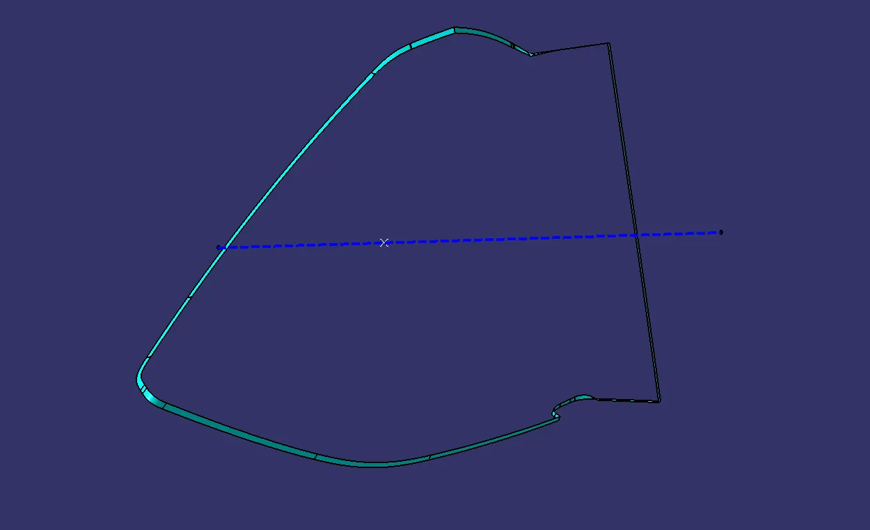
Finally, all the swept surfaces were trimmed and joined together.
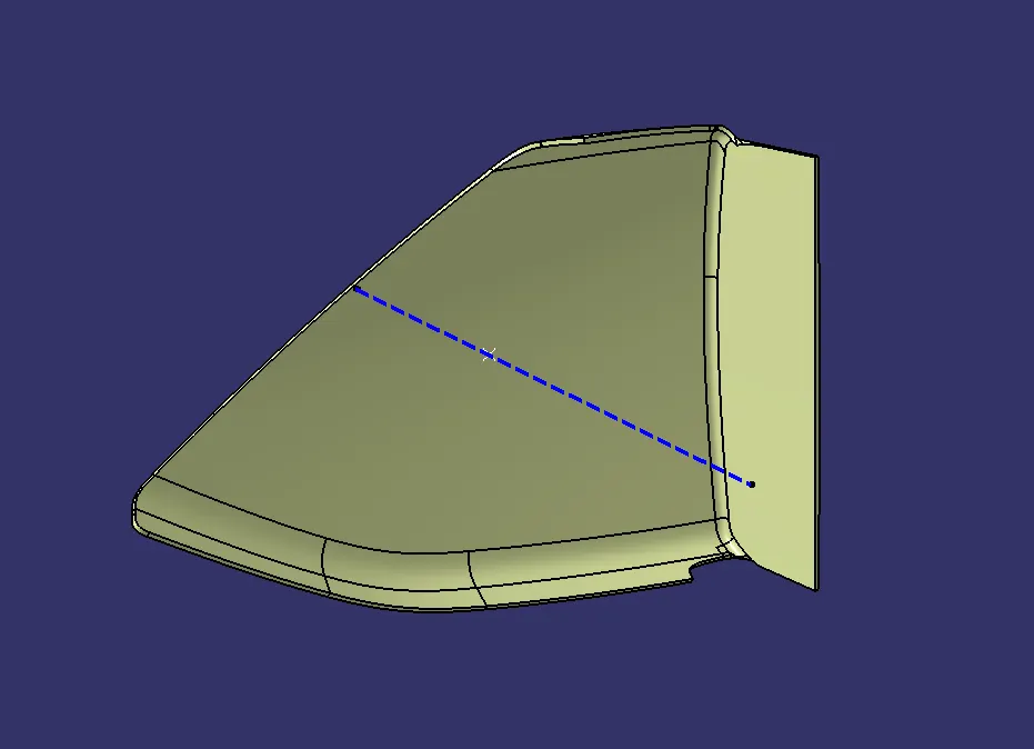
The procedure is the same for all components offsetting from the A-surface and working on patches if acquired so, and creating the C-surface using the sweep option at an angle of 3 degrees outwards with respect to tooling direction. In some areas, the 90-degree sweep was applied.
2. ARM REST:-
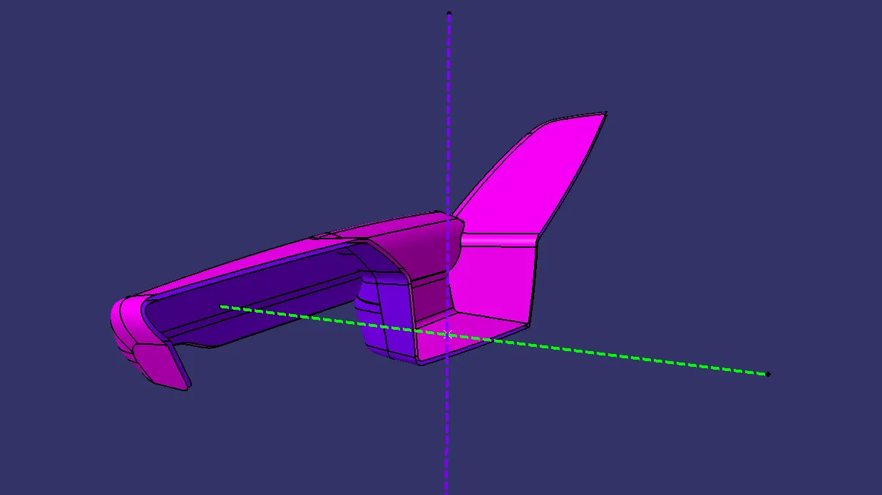
In Pink Color the A-Surface and Purple Color the B-Surface.
In arm rest there so many operations done so the Final Join is shown below.
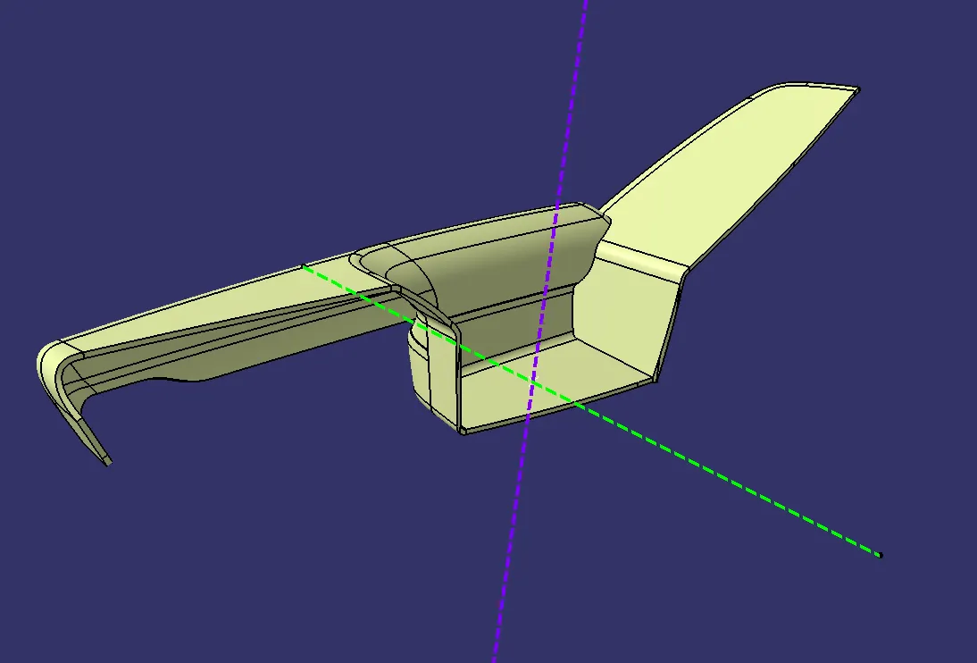
Final Join
3. BOTTLE HOLDER:-
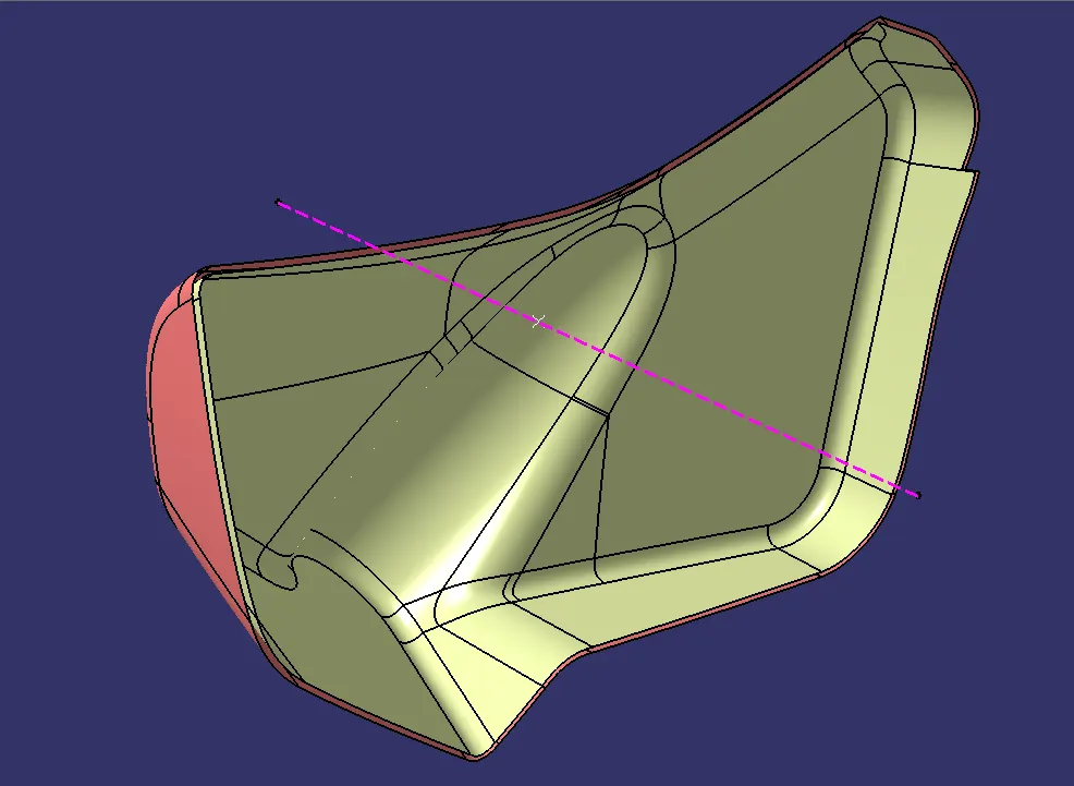
A and B Surface
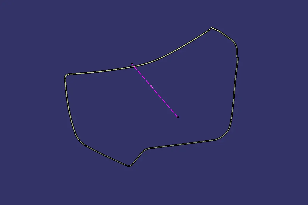
C Surface.
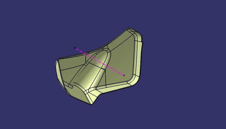
Final Join
4. LOWER SUBSTRATE:-
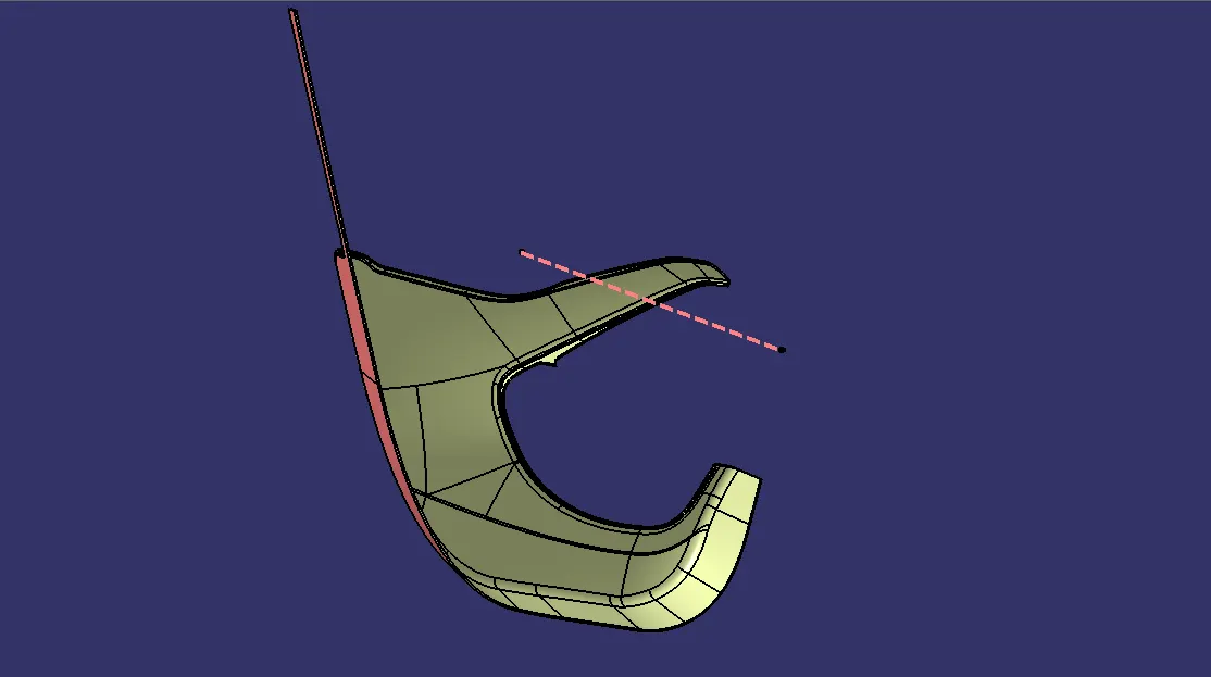
A and B Surface
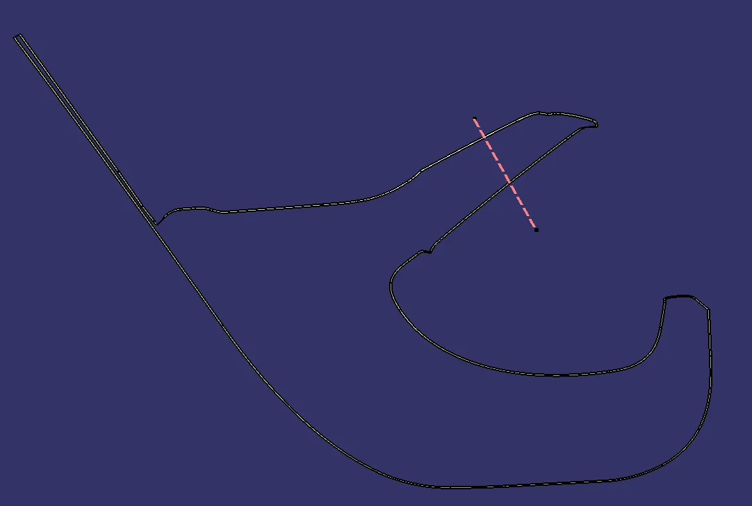
C Surface
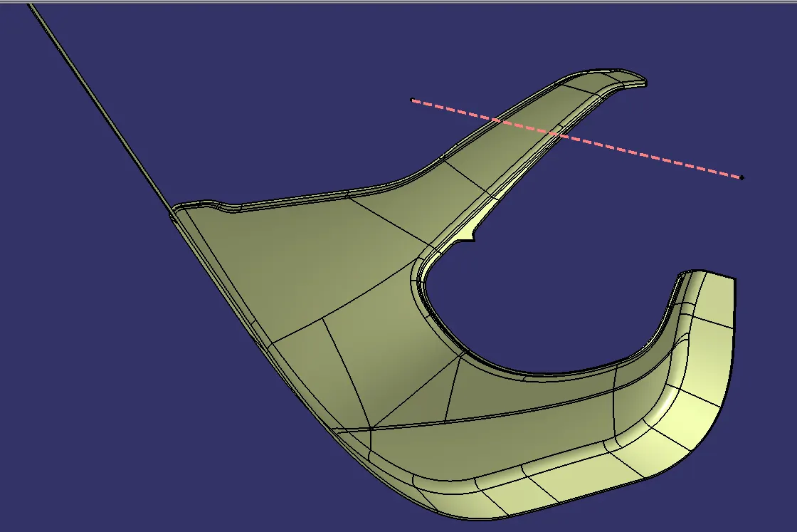
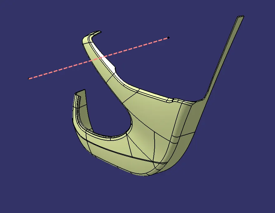
Final Join
Checking For Boundaries:-
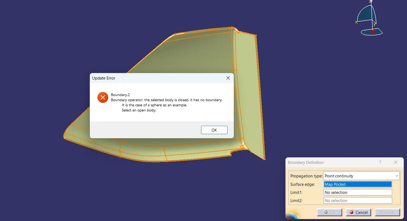
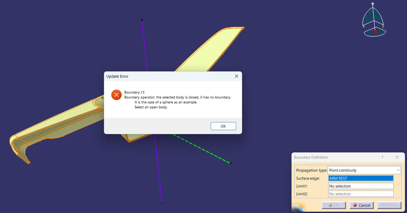
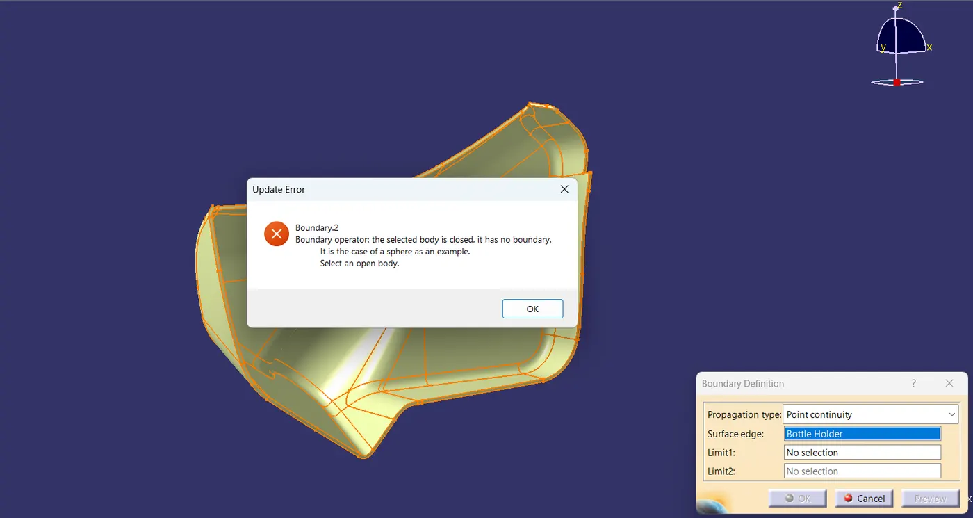
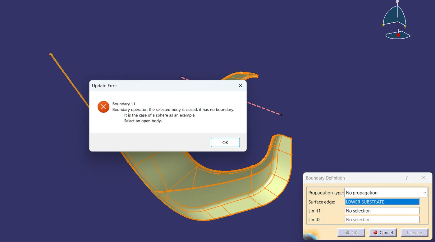
To make the plastic component a solid body we have to ensure that the component does not have any openings. Boundary checking helps us to find if there are any openings present in the component.
Map Pocket:-
ARM REST:-
BOTTLE HOLDER:-
LOWER SUBSTRATE:-
CONVERTING EACH ELEMENT INTO CLOSED BODY SURFACE:-
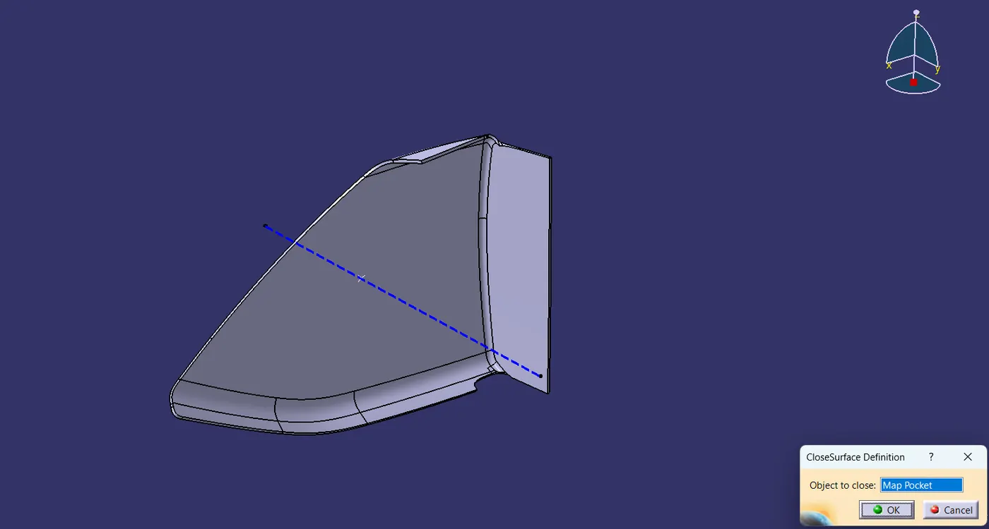
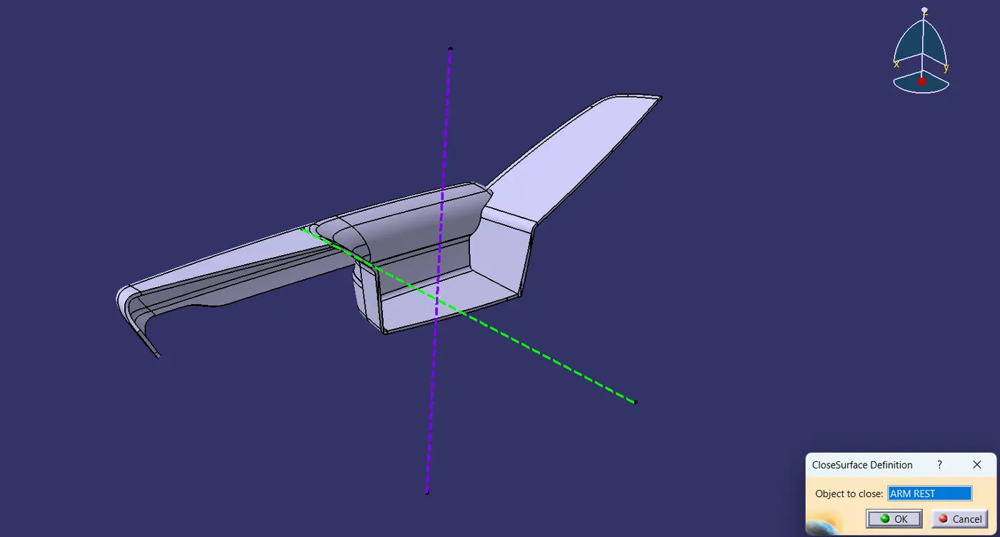
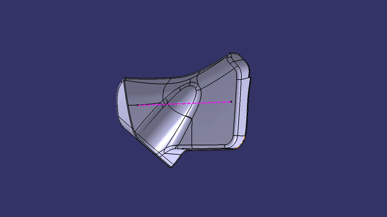
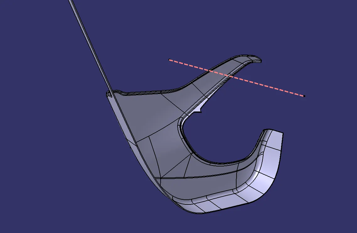
After checking the closed boundary of each element will go to part design where will insert a body and click on the closed surface option to convert the closed surface into a closed body.

1. MAP POCKET:-
2.ARM REST:-
3. BOTTLE HOLDER:-
4. LOWER SUBSTRATE:-
DRAFT ANALYSIS ON EACH CLOSED BODY:-
1. LOWER SUBSTRATE:-
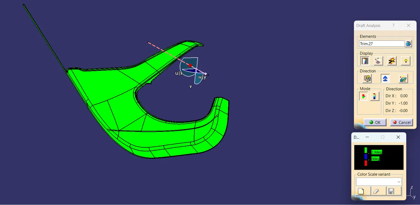
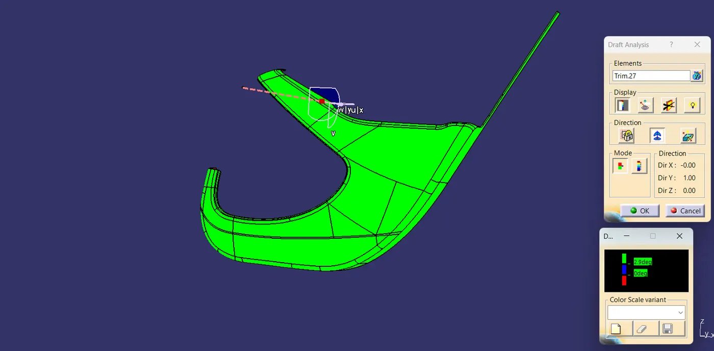
2.ARM REST:-
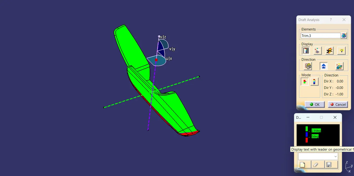
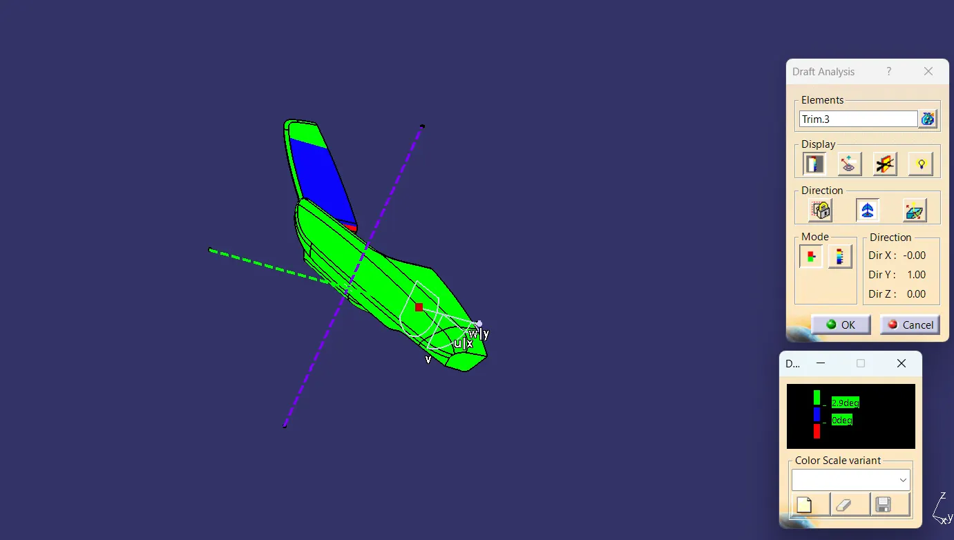
3. BOTTLE HOLDER:-
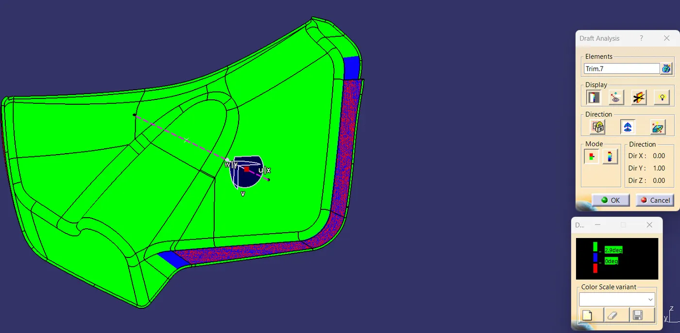
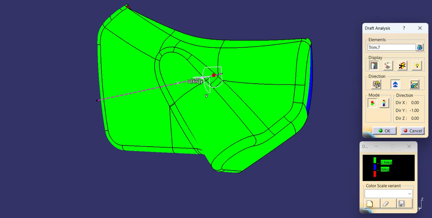
4. MAP POCKET:-
CREATION OF ATTACHMENT FEATURES ON B-SIDE:-
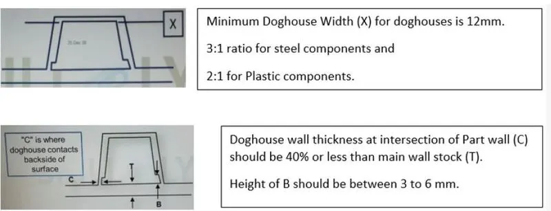
DESIGN RULES FOR DOGHOUSE:-
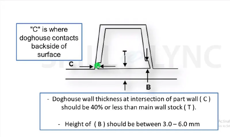
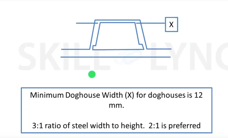
Also, the minimum distance between the walls at the top portion should be 12mm.

Design Rules for Ribs:-
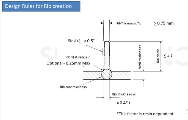
1. Draft: 0.5 degrees per side(minimum), but this value should not be high enough that it will cause failure for other considerations. For example, more drafts will result in less thickness at the top surface.
2. The thickness of ribs: 40% of wall thickness or 0.4*t where t is the wall thickness.
3. Height: <= 5 times the wall thickness i.e. 5*t.
4. Spacing (for more than 1 rib): 3:1-steel height/width ratio (maximum). h/w=3or2(preferred) where h is the height of the rib and "W" is the space between two ribs.
5. Minimum thickness at the tip:0.75.
6. Radius: 0.25mm max.
7. Ribs on the opposite side of the wall should be offset.
8. Ribs should be connected to other structural features where possible.
9. Rib root thickness should not be more than 30% of the wall thickness.
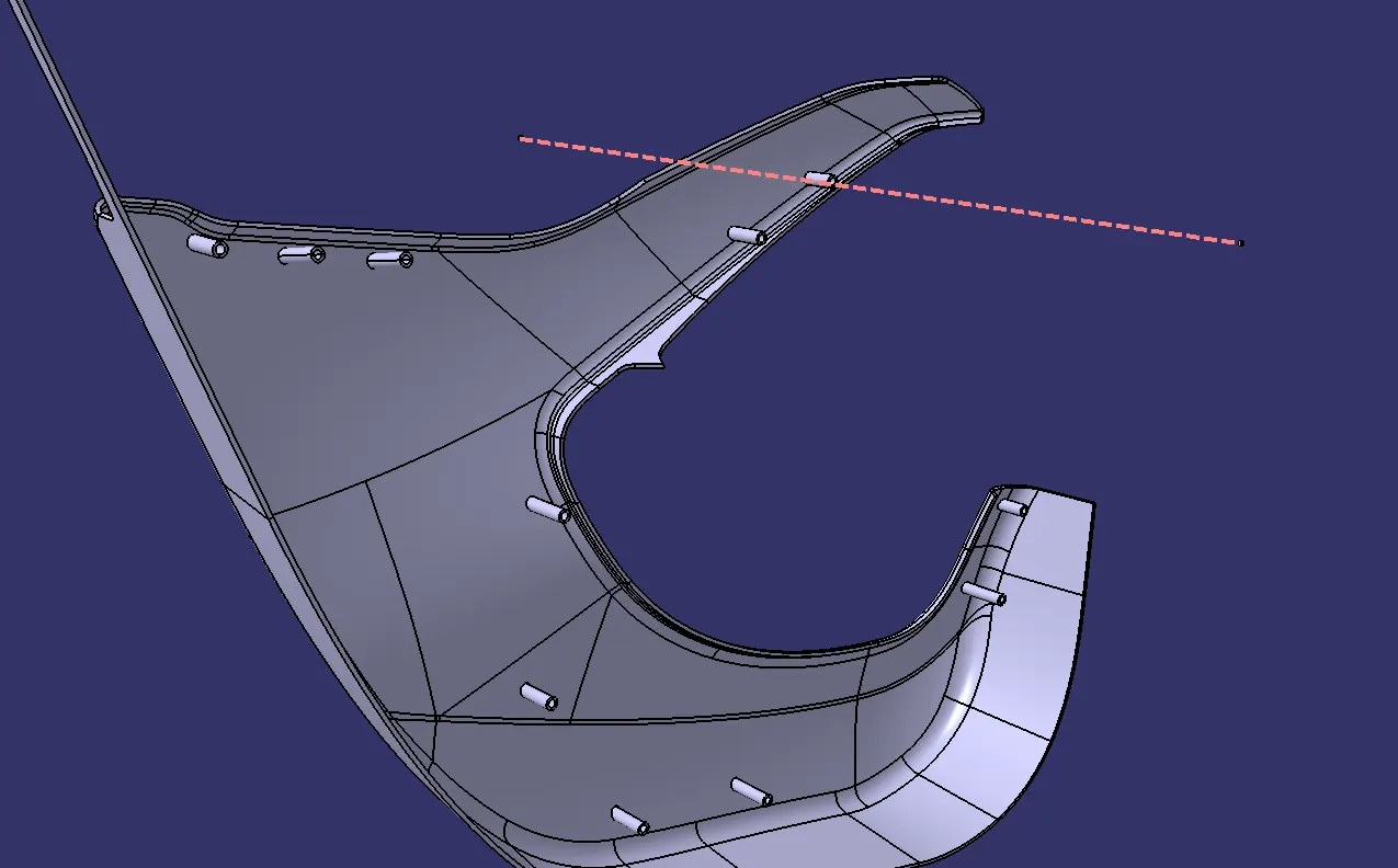
Thus following above all the guidelines a Dog house with Pushclip was created.
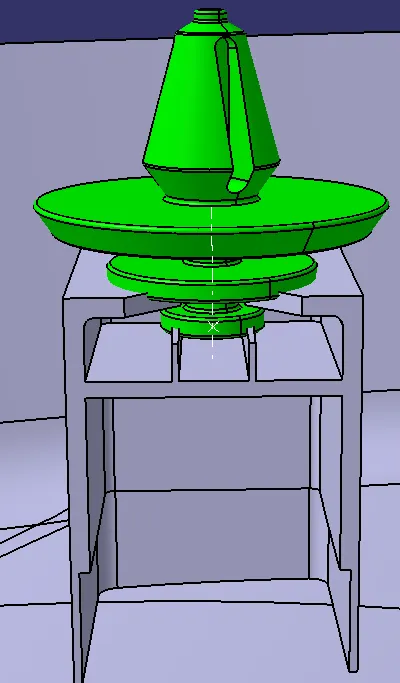
Doghouse with ribs inside in it and the Pushclip on the top.
Creation Of Flanges:-
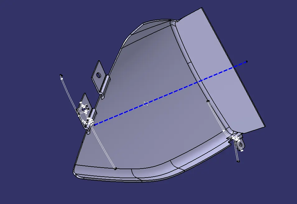
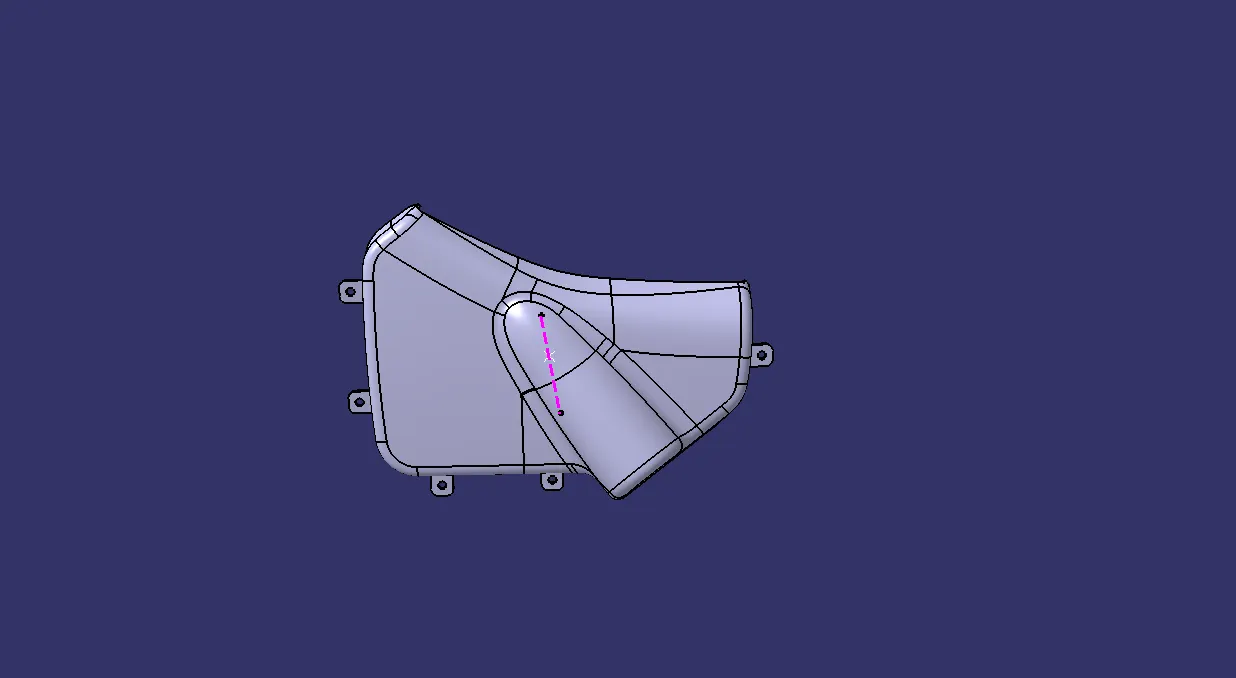
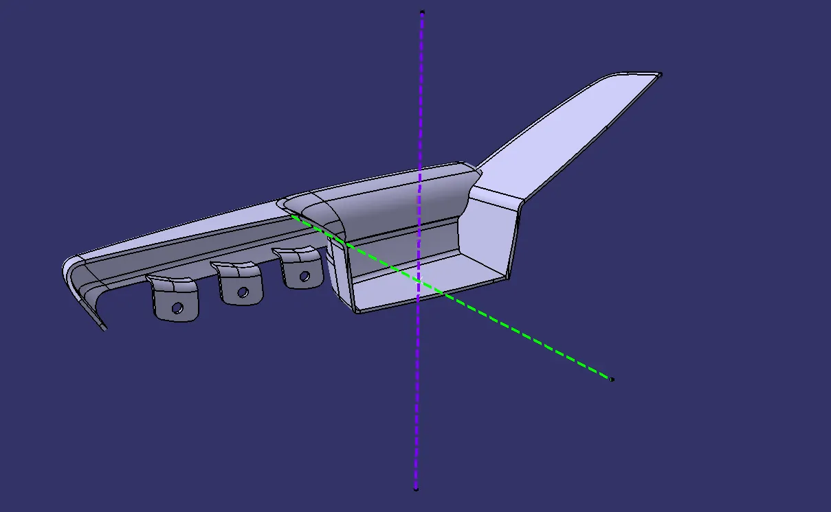
Flanges are created wherever required. Master sections are given so that the measurements are acquired and created as shown below.
Creation of Heat Stakes:-
Heat staking is a pulsed-heat process to join two or more parts out of which one at least is made of plastic. The process is to deform the plastic material using heat and force at a set process time. The bond is made by partially de-forming the plastic part in order to fix the others.
Heat stakes are made on the Lower substrate wherever the flanges are projected on the lower substrate.
Final Door Trim With Component with Attachments:-
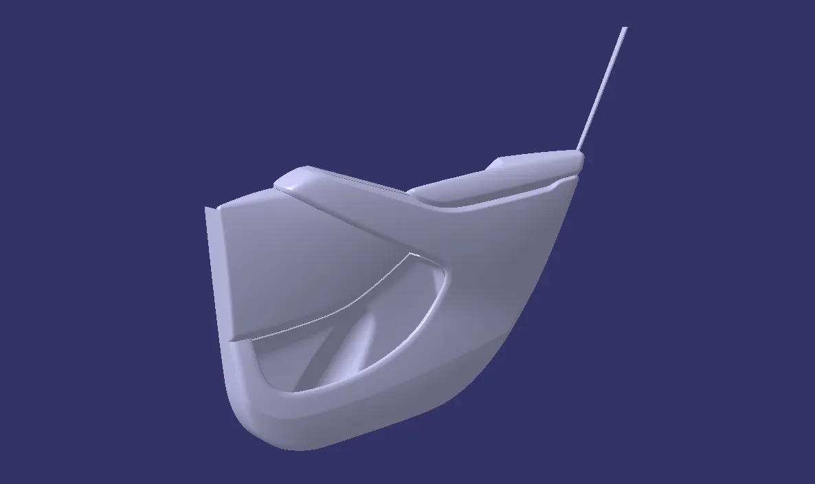
Final Door Trim With Aesthetic Look:-
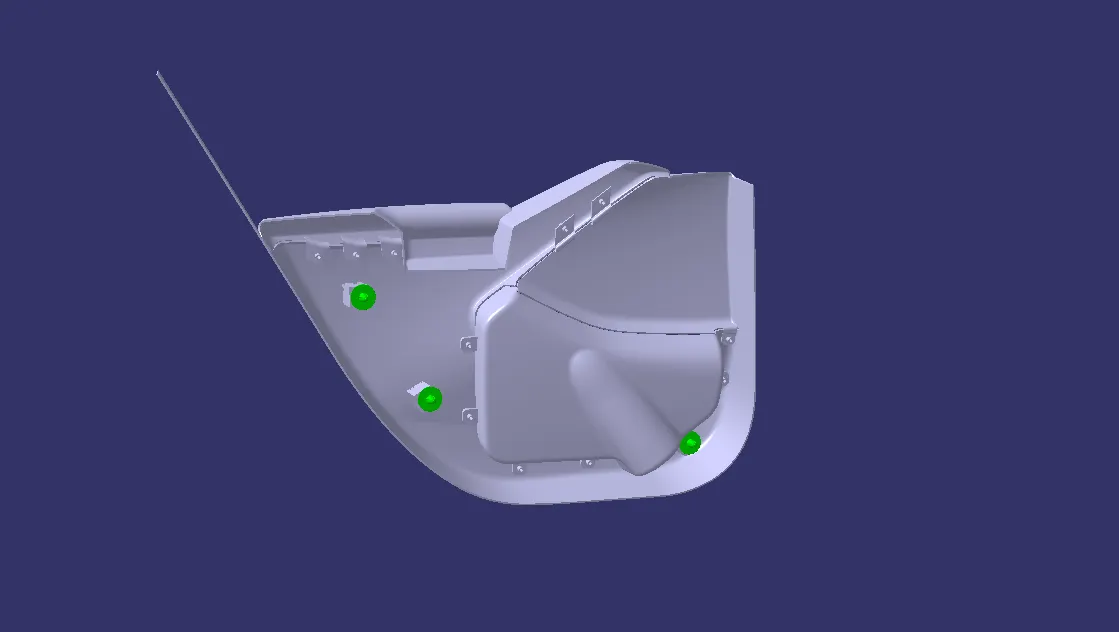
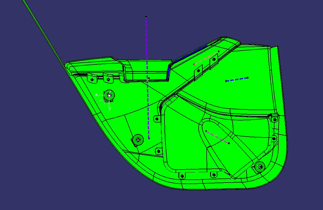
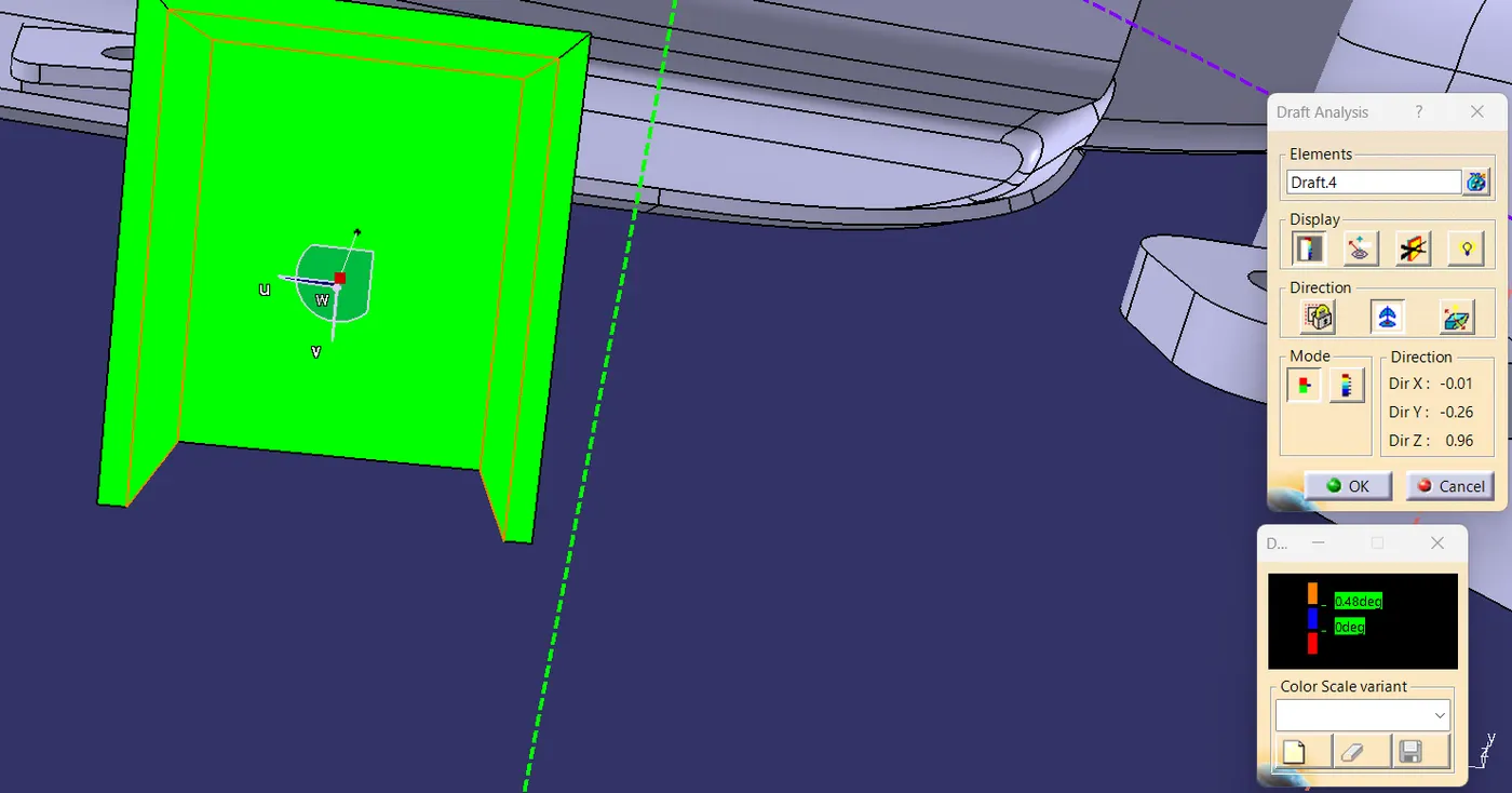
Final Draft Analysis :-
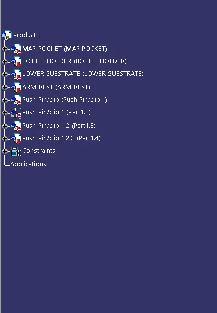
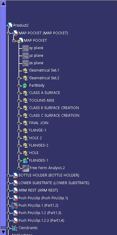
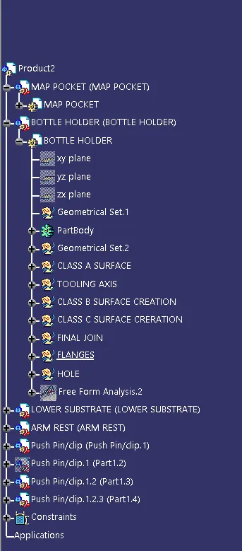
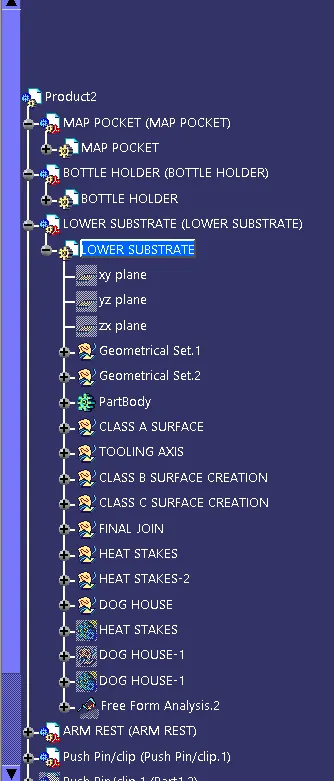
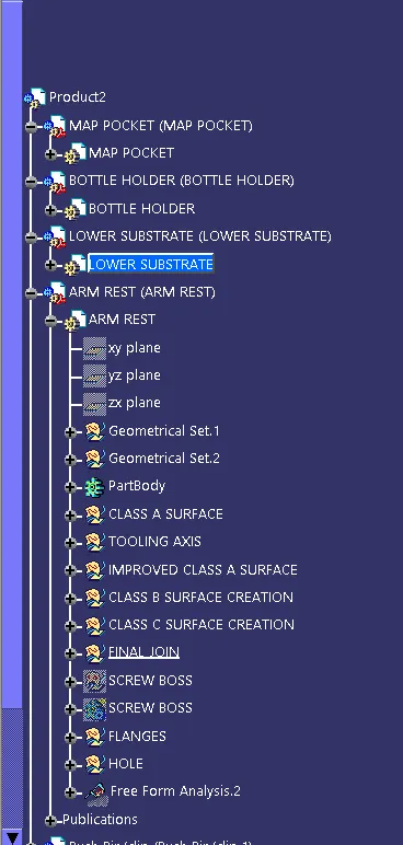
Tree Structure:-
Conclusion:-
1. The Door Trim is created using a shape design, Part workbench.
2. The model is Designed with a nominal draft angle of 3 degrees for the component and 0.5 degrees for the Attachment Features.
3. The closed body of the model is created using the closed body command in the part design workbench.
4. The attachment features in the model are designed following the design rules.
5. The tree structure is maintained clearly.