Week 9 - Challenge 3 - Bumper
CREATION OF BUMPER BODY FROM A-SURFACE:
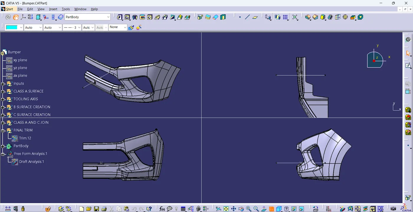
Aim:
To create a body of the Bumper from the input given which is the A-surface of the Bumper. The created body should be closed solid volume which should be feasible for manufacturing and Tooling. The draft angle and draft analysis of the component also be done.
Input Given:
1. A-surface
2. Thickness of the component is 3mm.
3. Draft angle is 3 degrees.
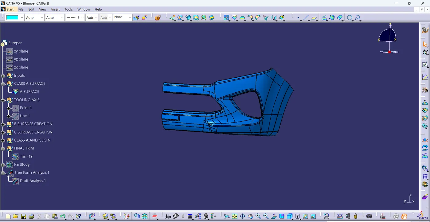
Given below is A surface.
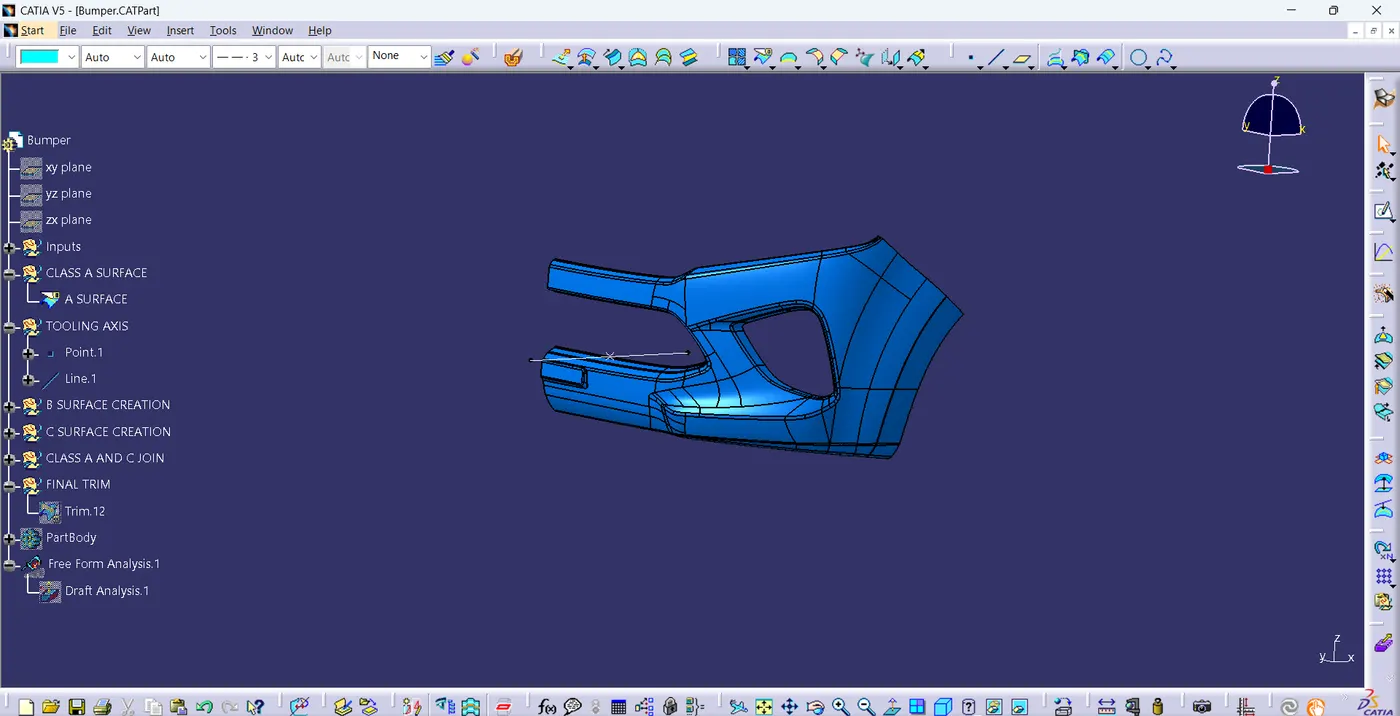
Creation of Tooling Axis:
Tooling Axis is the direction in which core and cavity of mold open. The Axis is very important to determine the orientation of the component in mold, core, and cavity design.
The A-surface is viewed in all axises X, Y, and Z.
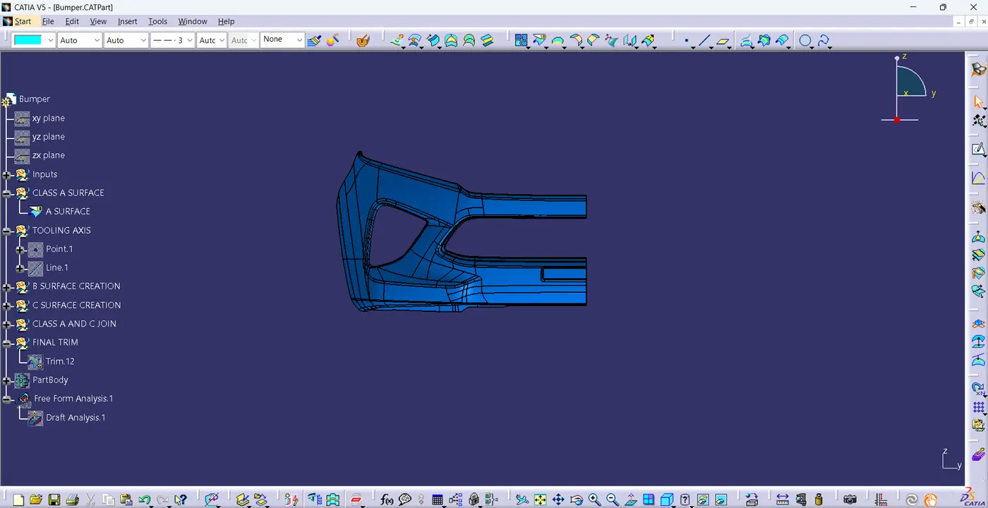
Surface viewed in X axis.
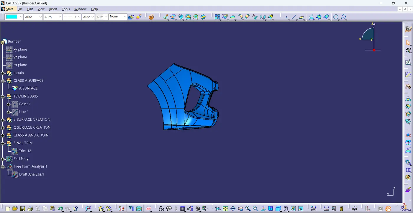
In Y-axis.
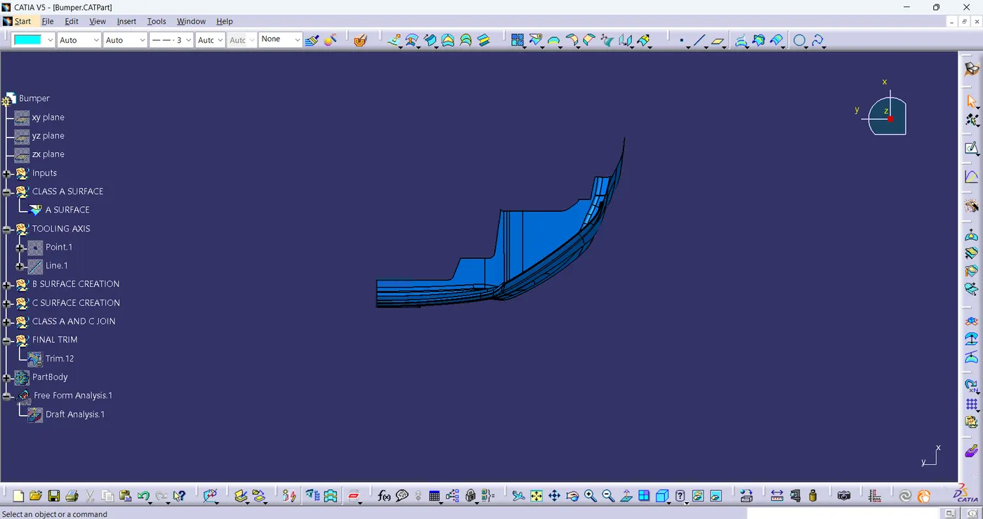
In Z-axis.
After viewing all axises it's founded that the X-axis is the best suitable axis for the formation of the Tooling axis.
For creating Tooling axis, will first create a point on the surface of the Bumper.
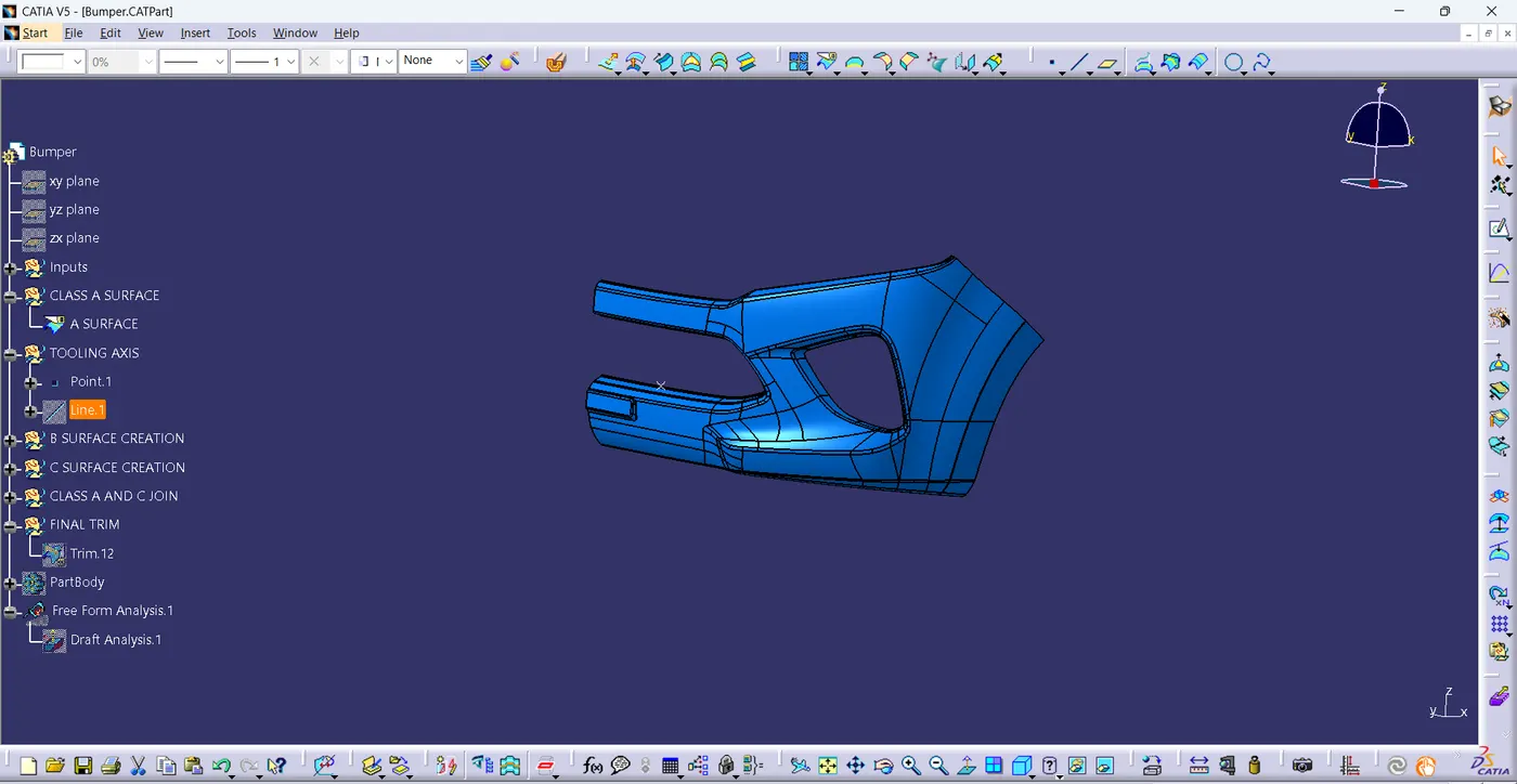
After that will draw the line with the help of that point which will be our Tooling axis.
Creation of B-surface:
In previous surfaces we have seen different methods for creating the B-surface which will either extract two or three components untrim them and extrude them, then give the given offset value.
But this will create a whole offset of A-surface of 3mm.
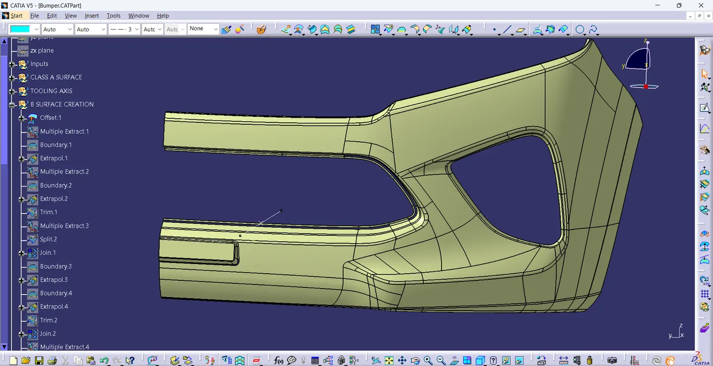
Now as there are some gaps created in the B-surface will work on these gaps to completely make a B-surface, for these will use different tools like extract, trim, extrude, and join to create a B-surface.
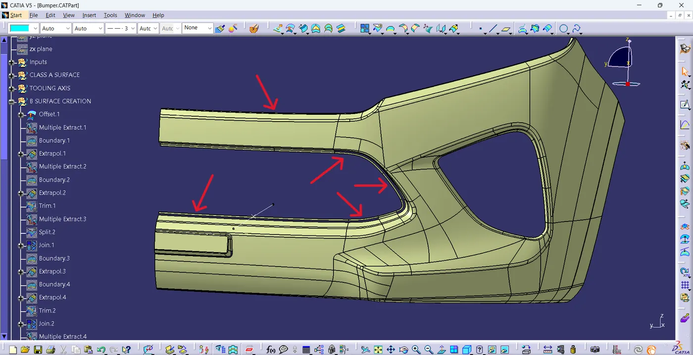
By performing the above-mentioned operations on the Offset surface the final output will be shown below:-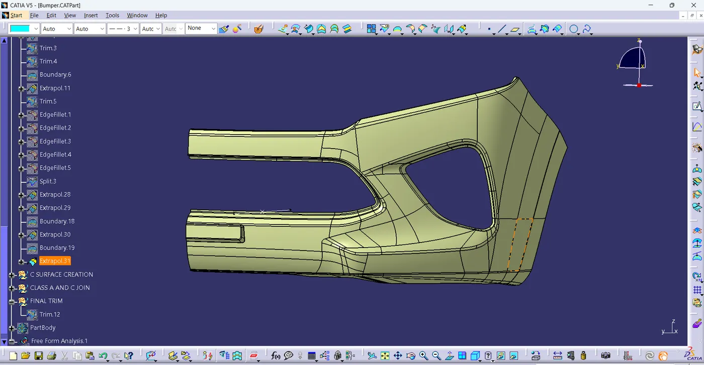
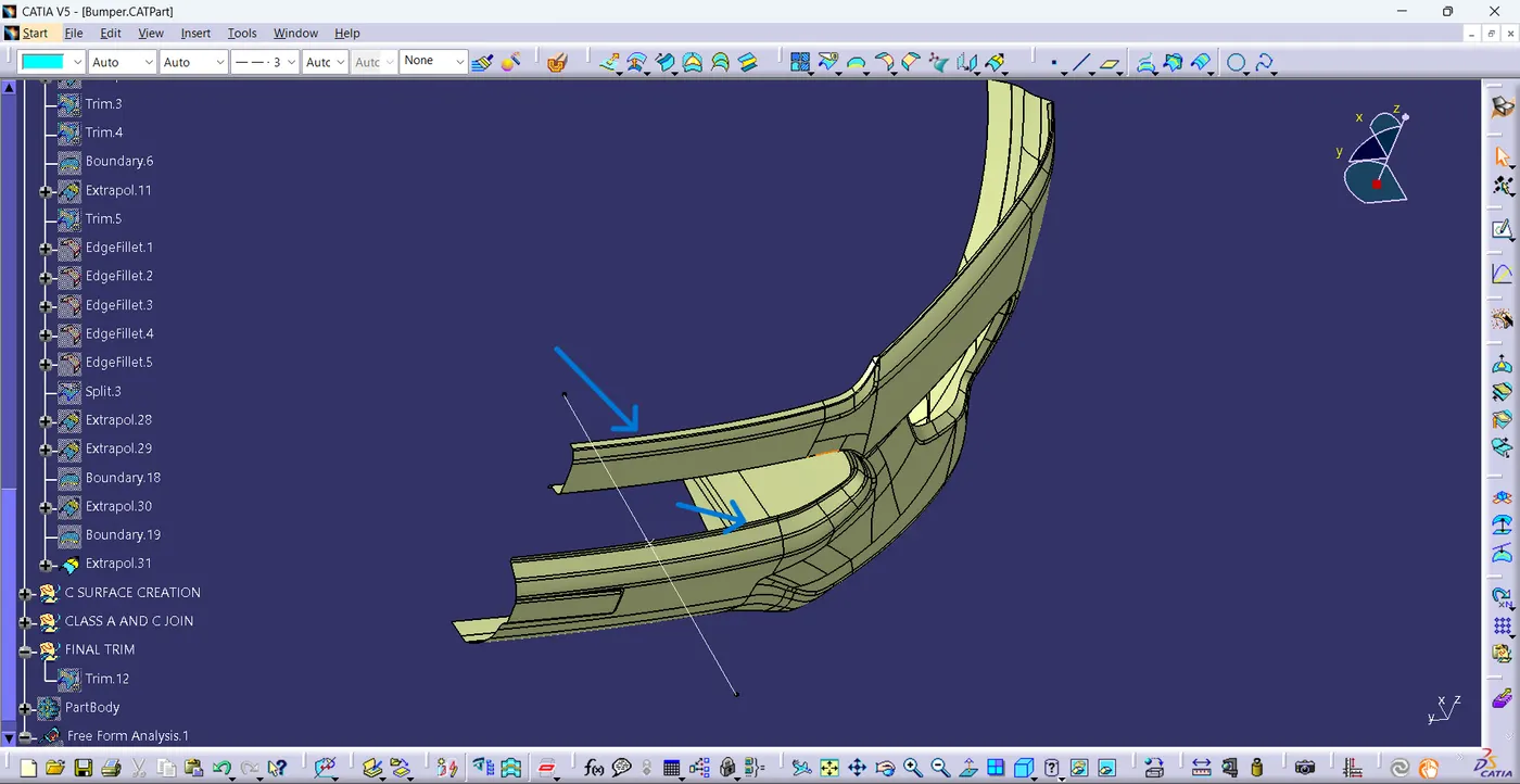
That's how our B-surface should look after performing extract, extrude, and join operation on the offset.
Creation of C-Surface:
Now after creating the B-surface will work on the creation of the C-surface an important surface that helps to connect the B-surface and A-surface and form the desired component.
The C-surface is created with the help of the A-surface, which will create a boundary around the outer surface of the A-surface and then will sweep it around the draft direction.
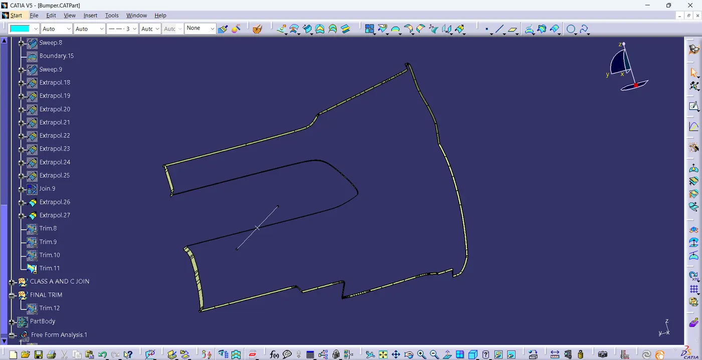
This will be our final C-surface the output we get by using the different operations like sweep, extract, extrapolating, and trim.
Creation of A and C-Surface:
After creating the C-surface will join the A and C-surface together.
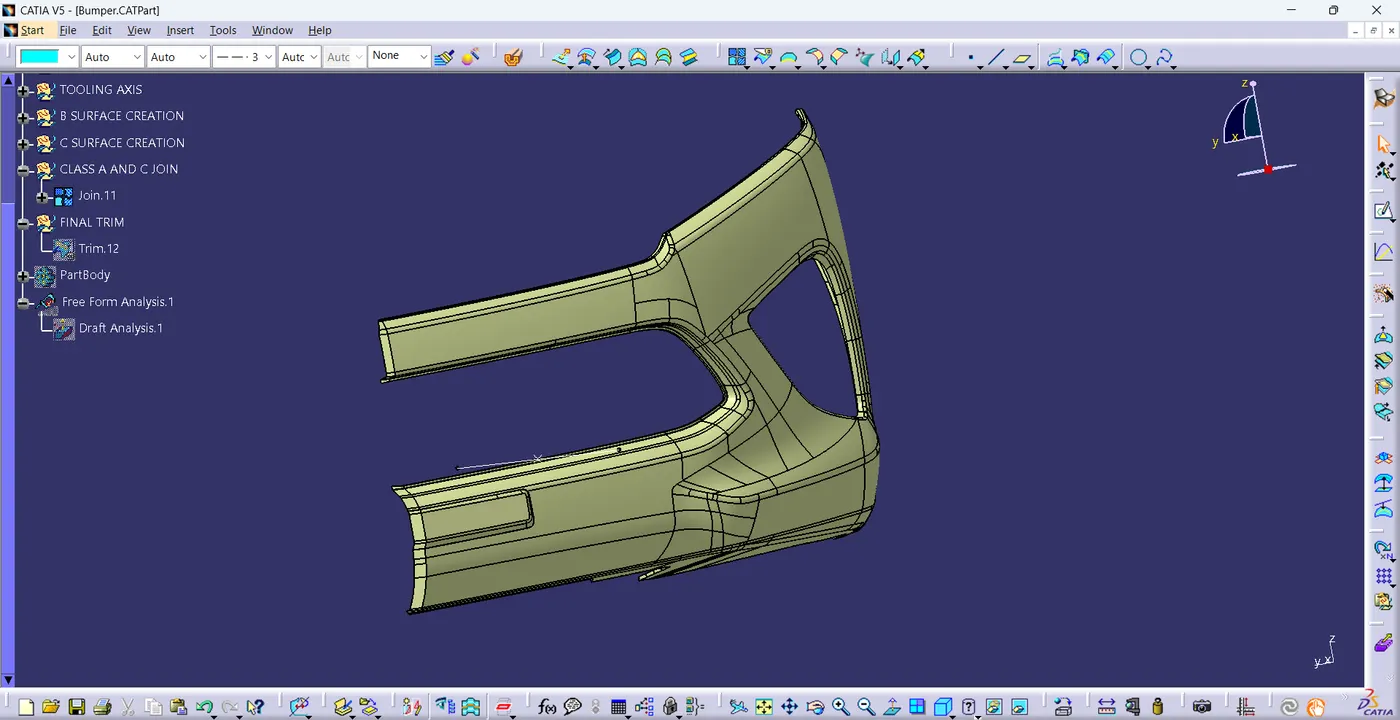
That's how the component should be looked after when we join the A-surface and C-surface together.
Creation of A+B+C-Surface/Final Surface:
Now will unhide the B-surface with the A+C-surface and trim both surfaces together, while trimming we have to ensure that the B-surface is extrapolating enough to intersect with the A+C-surface so that we can trim it properly.
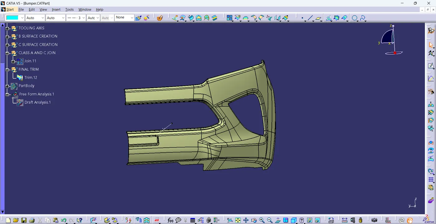
This will be the Final surface which will be created after trimming of A+C-surface and B-surface together.
Also before creating the Closed surface ensure that the surface is closed and has no other boundary, click on the boundary surface and click on the surface created and a dialogue box with an error will come up saying the body is closed body.
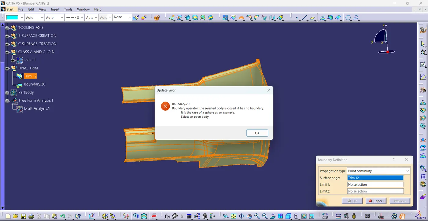
After getting the dialogue box it means that the product is a closed product and there is no boundary.
Creation of Closed Surface:
Now we gonna select the PartBody and create a solid surface out of the Final Surface.
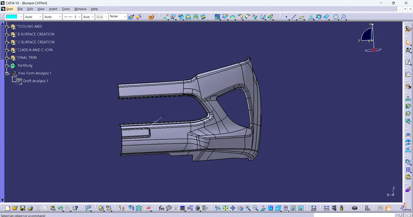
Now go to the Part Assembly then click on the closed surface and click on the Final surface and the catia will create a Solid body out of it.
Draft Analysis:
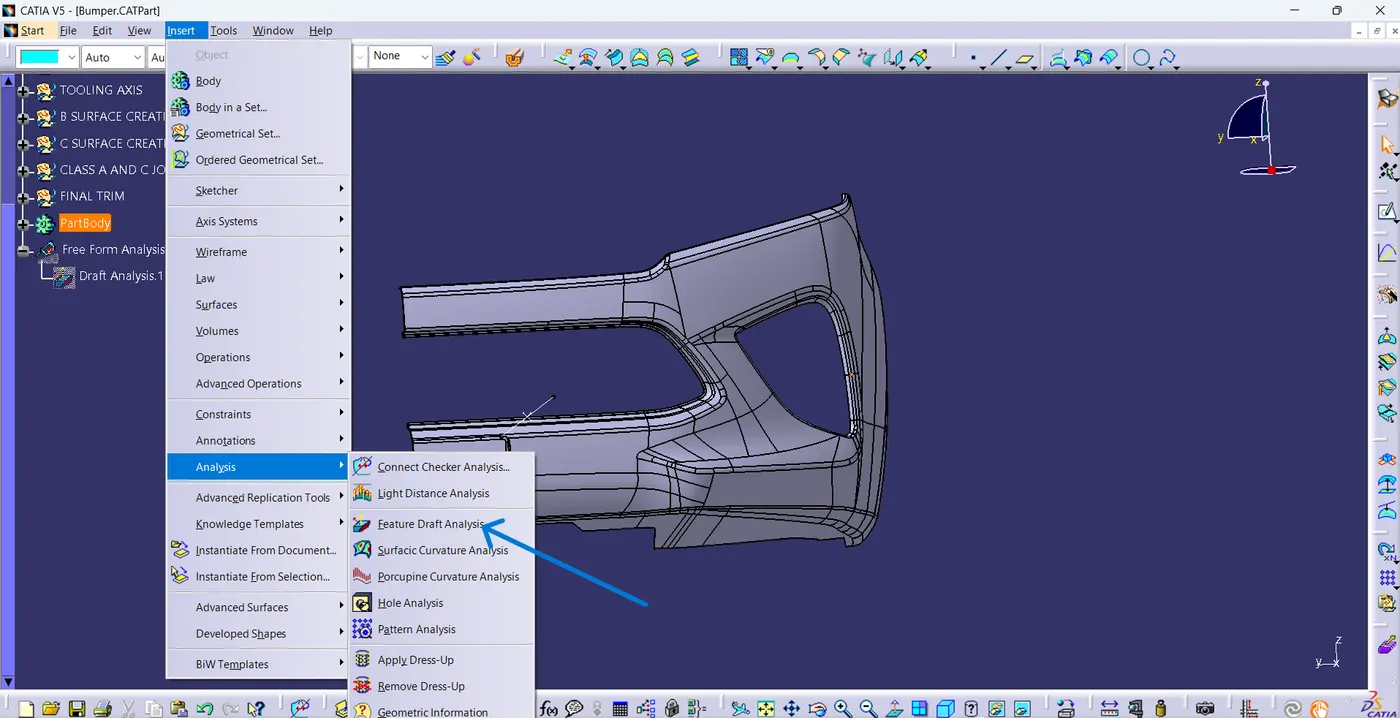
Now after creating the Part Body click on the insert then go to the Analysis and from there select the Features draft analysis
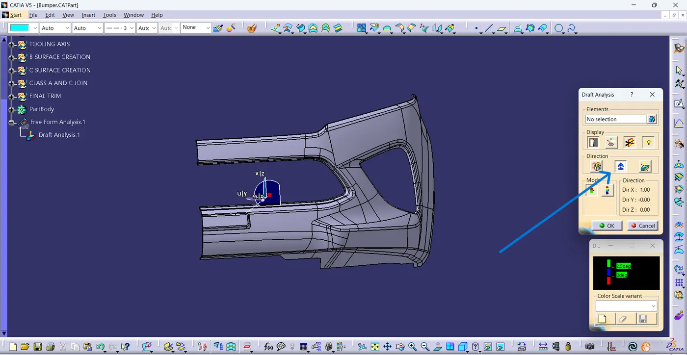
After that click on the compass and place the compass on the tooling direction.
Then click on the surface and check that the component color is under the given Draft angle, more or less than the draft angle.
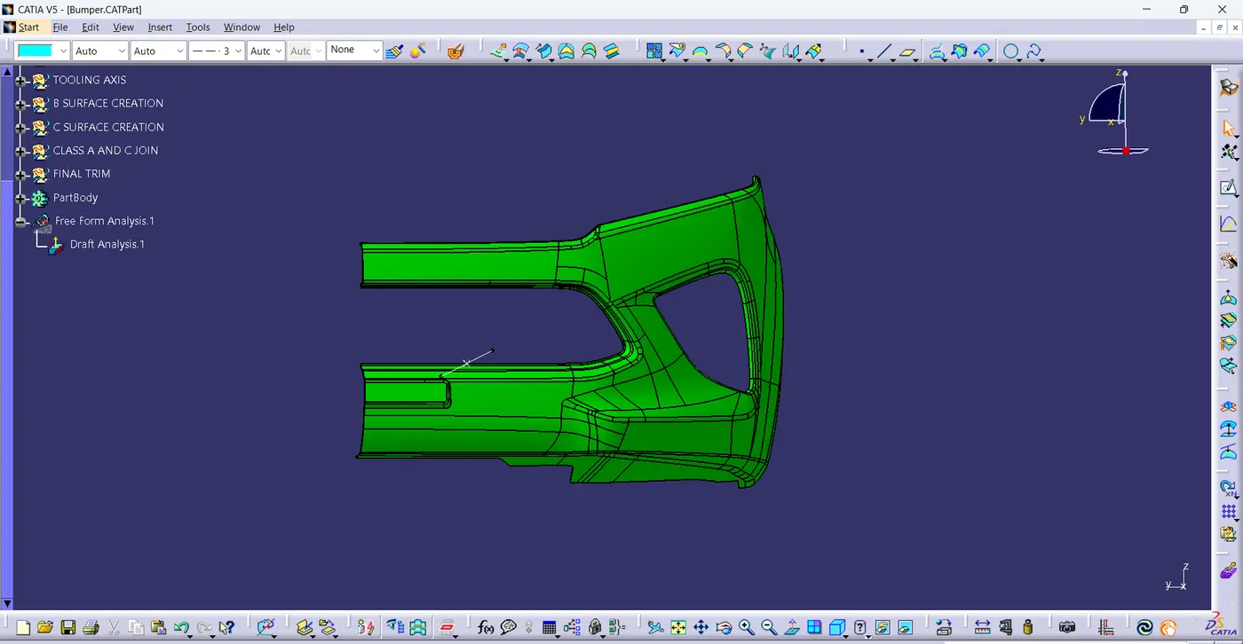
The Final output will be this after doing a draft analysis.
Model Tree:
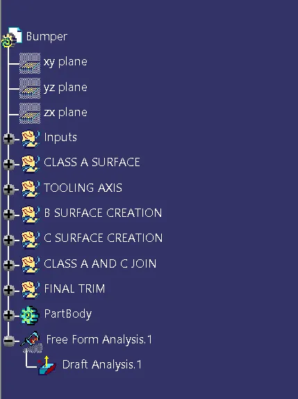
The model tree shows that all geometrical sets are named for clarity.
Conclusion:
The draft analysis of the component showed that the component is feasible to be molded without any issues.
Thus it satisfies all design and manufacturing criteria needed for a proper part.
This concludes the proper report of the Design of the Bumper Body.