Week 10 - Challenge 1- Attachment Feature Creation (Ribs & Screw Boss)
AIM:-
Create Ribs and Screw Bosses on Screw Door Handle.
INTRODUCTION:-
Ribs and Screw Bosses are engineering features that are created on the B surface of the Plastic Components.
RIBS:-
Ribs are used to strengthen the walls of your mould without increasing wall thickness which means that you minimise the problems that come into play when the wall thickness has to be increased.
In essence, if the wall is too thick, warping and sinking can result so that the entire design may need to be rejected.
SCREW BOSSES:-
Boss features are commonly found in injection molding designs. They are used to aid in the assembly of molded parts by providing a channel for a screw, Designing plastic screw bosses is fairly straightforward but there are a few considerations to ensure a strong connection between parts and mitigate cosmetic defects.
OBJECTIVE:
1. Create a Tooling Axis from the given Class-A Surface.
2. Then create Class-B and Class-C surfaces from the Class-A surface.
3. Then create Part Body with Class-A, B, and C Surface.
4. Then create the Ribs and Screw Boss on the Part Body.
CREATION OF TOOLING AXIS:-
First will rotate the Class-A surface in X, Y, and Z directions and observe in which direction we can have the access to Class-A surface. So, in Y axises the surface can be accessed easily.
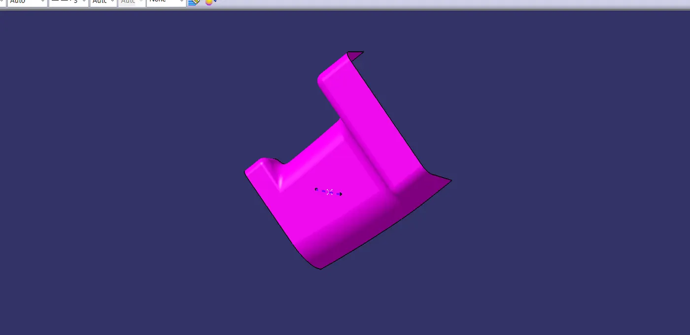
Draw a point on the surface and then create a line on it in the Y-axis direction.
CREATION OF B-SURFACE:-
Now will create the B-surface from the Class-A surface. Will extract the Class-A surface at 2.5mm in the opposite direction.
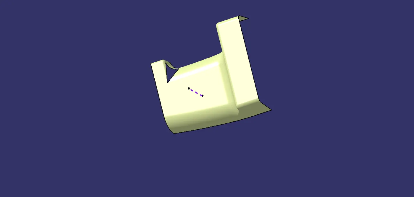
As seen the extracted surface is not completely extracted there is a gap in the surface, now will use the multisection and extract command to join the surface with the extracted surface and create a Class-B surface.
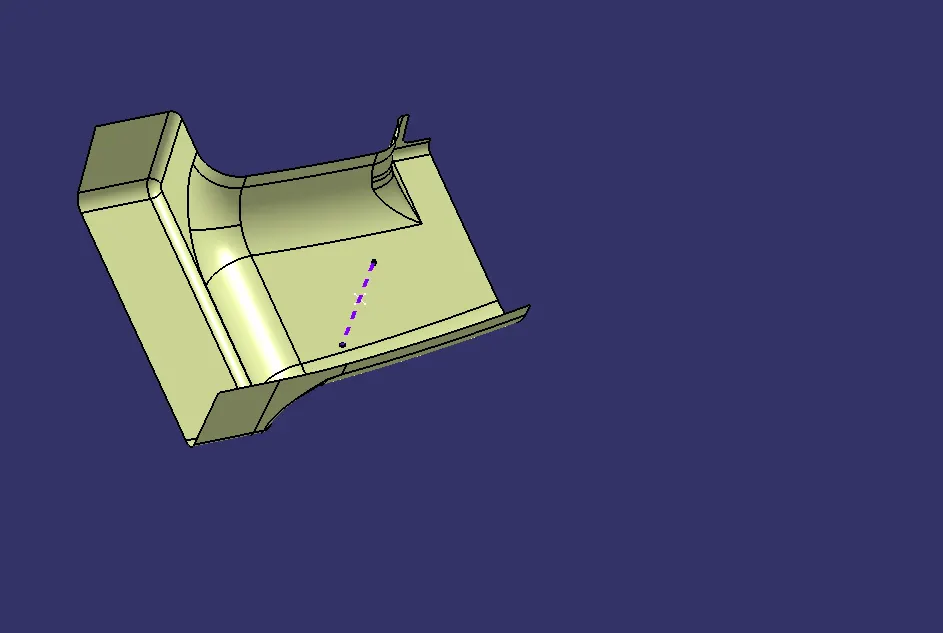
This will be our final Class-B surface.
CREATION OF CLASS-C SURFACE:-
Now will create the Class-C surface with the Class-A surface, Will unhide the Class-A surface create a Boundary from it, and then using the sweep command sweep the boundary with the surface using the reference surface at 90 degrees.
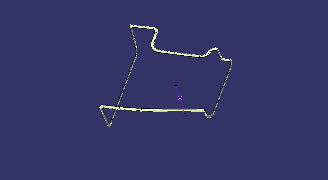
These will be our Class-C surface.
CREATION OF CLASS-A + B + C SURFACE:-
Will unhide all the surfaces and then join all of them together and form the Final Surface.
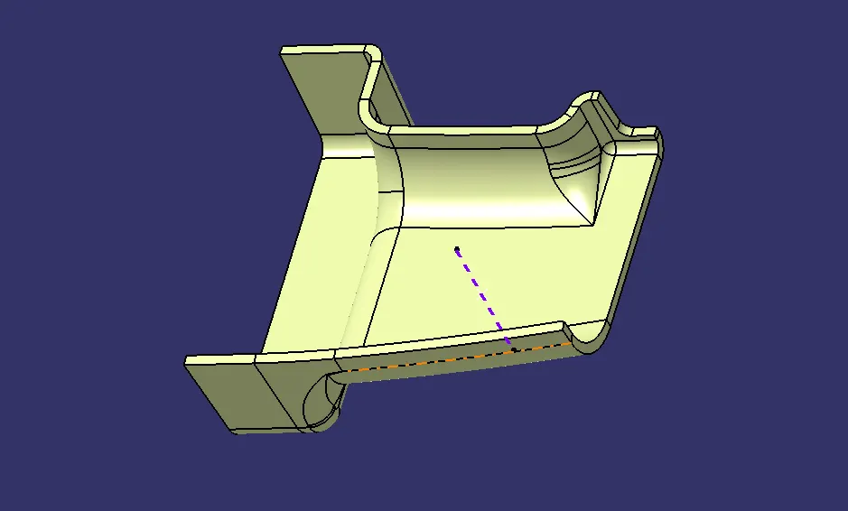
That will be our Final output. Now will create a Solid surface from the above-formed surface.
CREATION OF SOLID BODY:-
Will go to part body select it and define it, then go to part assembly and then click on the close surface, then click on the Final surface to form the solid surface.
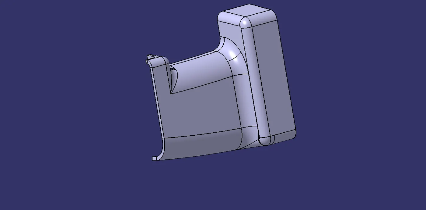
CREATION OF RIBS:-
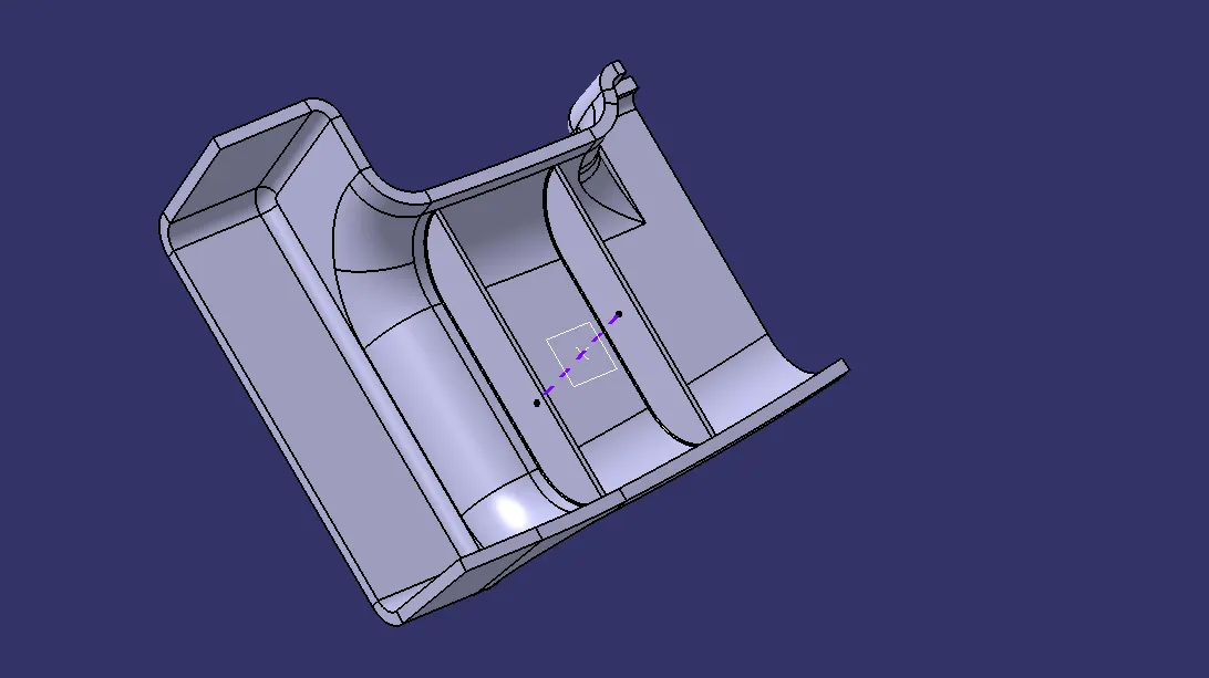
Now will create the ribs for the given surface below the diagram is the instruction to form ribs.
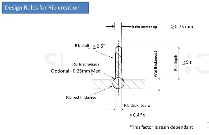
Create the sketch for the ribs on the surface and extrude the sketch with reference to the tooling axis, other method is to pad the sketch with reference to the tooling axis.
Then Union Trim the extrude ribs with the door handle.
Will give a draft with the base surface and then fillet the edges as the given value.
CREATION OF SCREW BOSS:-
Now after the creation of Ribs will work on the creation of Screww Boss, Below diagaram represents the value to be considered while creating Svrew Bosses.
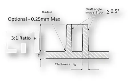
W=0.6T
The draft angle inside and outside is 0.5 degrees.
Height to diameter ratio -3:1.
Radii(fillet) - 0.25mm (maximum)
Create the sketch and extrude the Screw bosses.
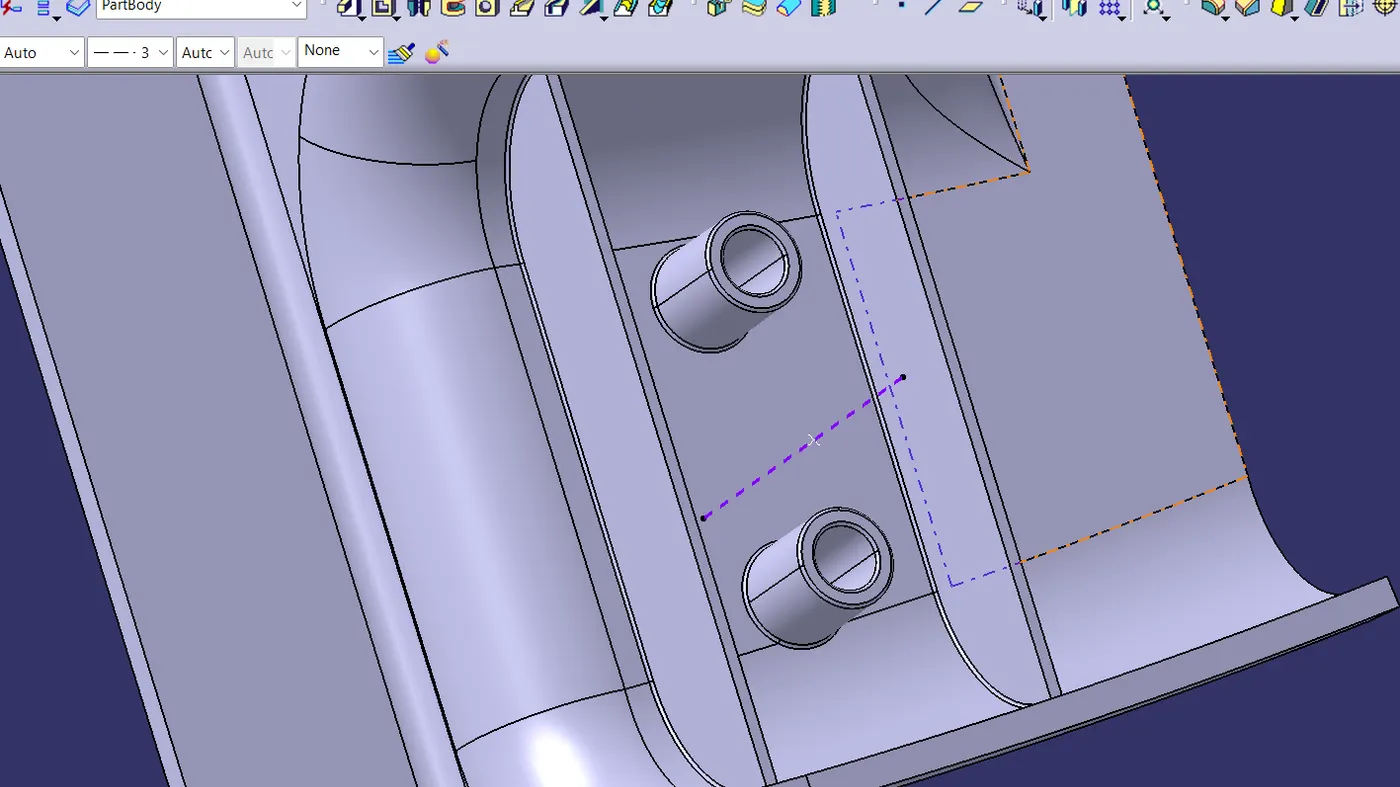
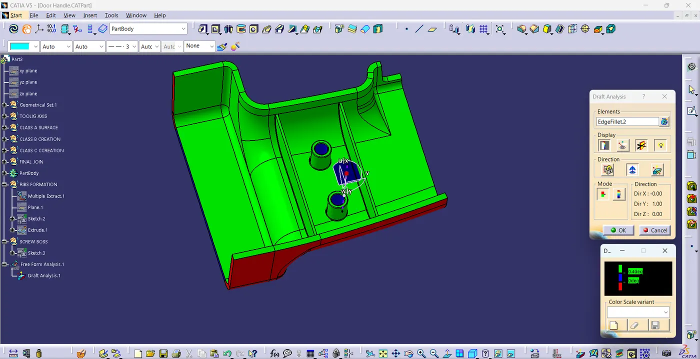
After giving the draft and fillets to both Screw Bosses and Ribs the Final Product will be shown Below:-
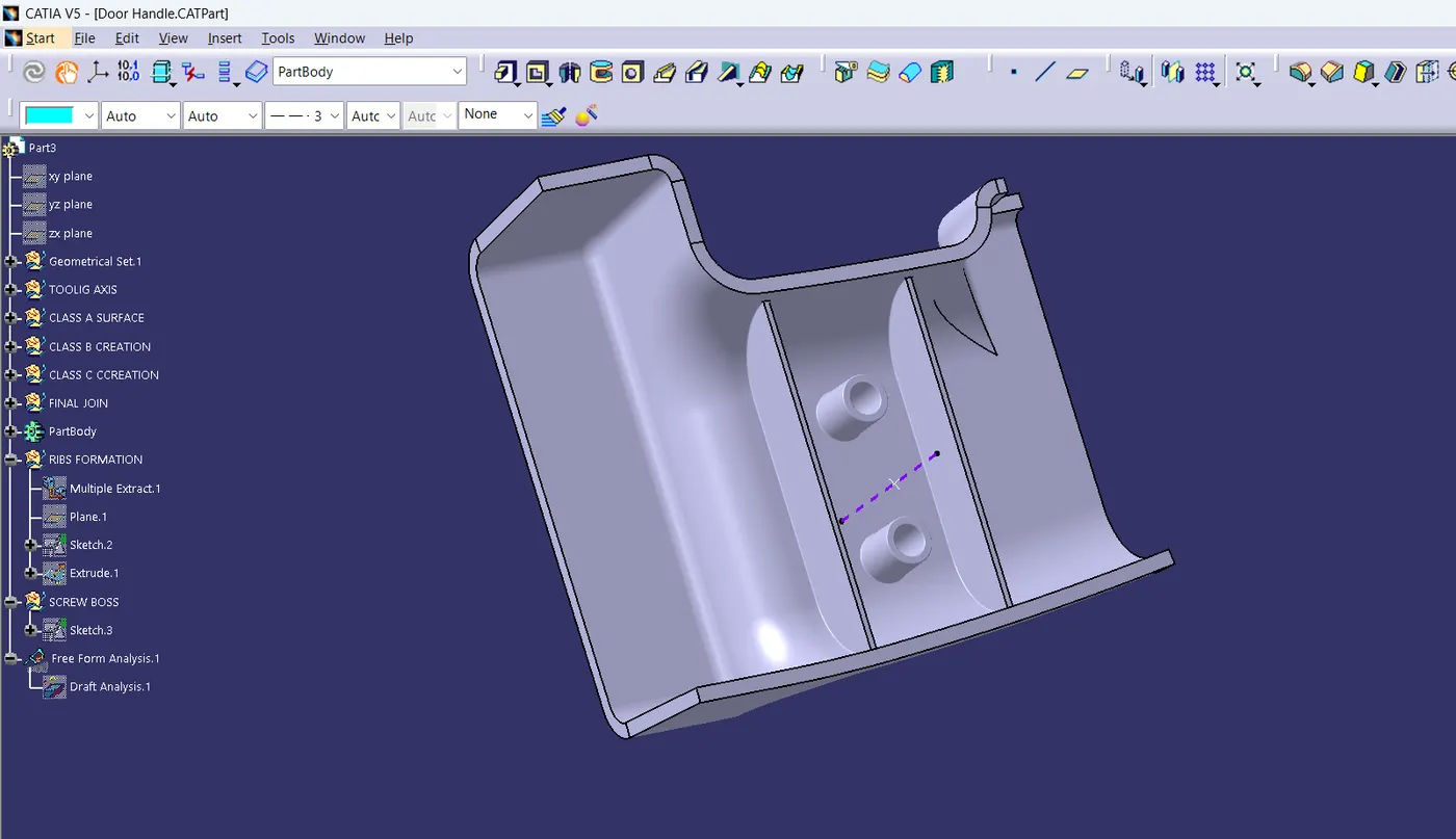
DRAFT ANALYSIS:-