Week 12- Final project
DEVELOPMENT OF A DOOR TRIM PANEL:
Aim:
To design and development of door trim panel using CATIA V5 with given Class A surface along with master section as reference. And also create the heat stakes, locators and dog houses as per the design rules.
Objectives:
- Create thickened part using master section for reference
- Create the mounting features as per design guidelines in the industry and with master sections
- Apply material details
- To draft analysis & Tooling analysis
Construction strategy:
- To create the tooling axis of given Class A surface and do the draft analysis of given Class A surface.
- To create the Class B surface for the given Class A surface.
- To create the Class C surface.
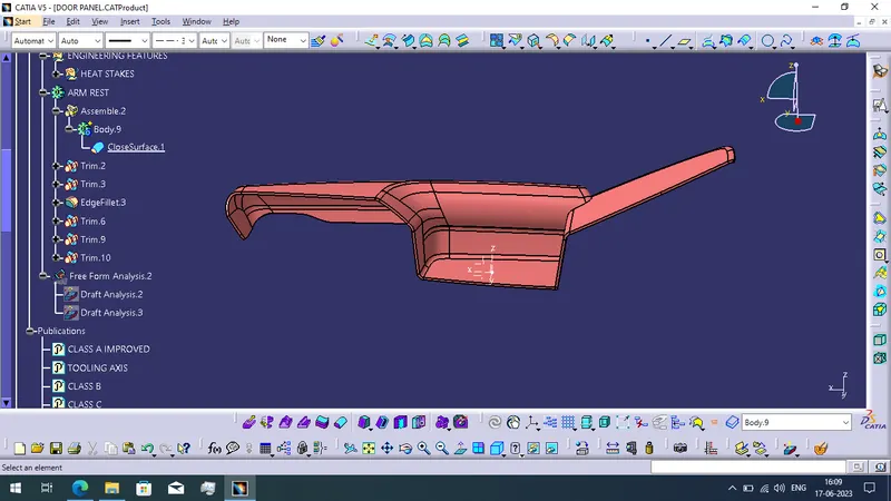
- When completed to create the Class C surface then use the close surface method to create the solid body of the component.
- Do this above procedure for creating the solid body of all 4 component.
- When complete to create the solid body then add the 4 components in the assembly workbench.
- Next we create the attachment and engineering features of Heat Stakes, Locators, Dog House and Flange with reference of given master section.
- When completing to create the mounting features then add the push pin to the created dog house using coincide constraints.
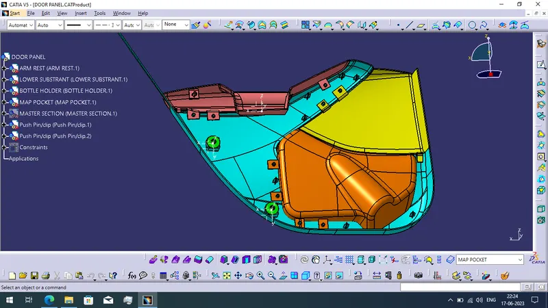
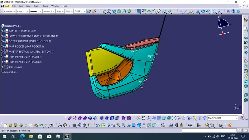
- Finally we completed to create the door trim panel.
CREATING SOLID BODY OF THE DOOR TRIM PANEL COMPONENTS:
DOOR ARM REST:
To create the arm rest using given Class A surface. We follow the above steps to create the arm rest component.
Creation of Tooling Axis:
- Extract the base patch of the arm rest surface and create the point using the surface point type method.
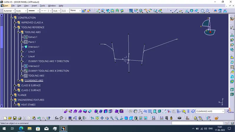
- Then use the intersect command for ZX plane and Class A surface with axis system of point reference. Now we create the dummy tooling axis of y direction.
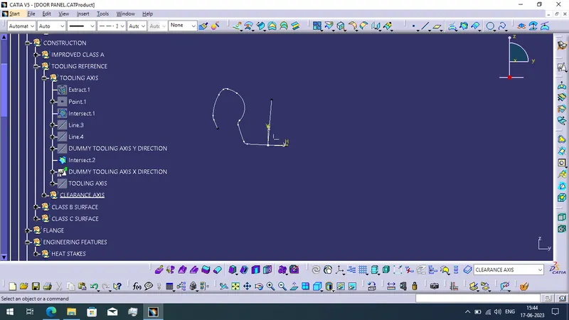
- Next we create dummy tooling axis with reference of X axis.
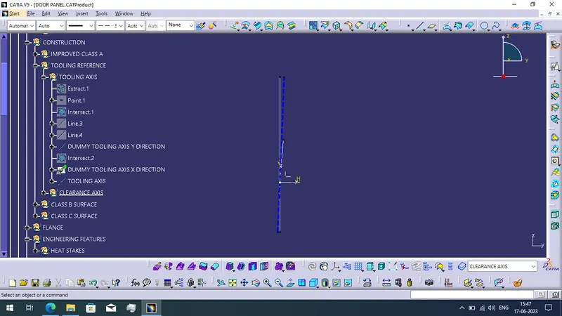
- Finally we get the tooling axis for using bisecting method of dummy tooling axis of X direction and Y direction.
Creating Clearance Axis:
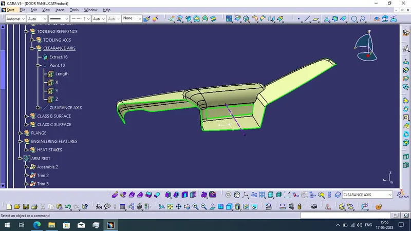
In this arm rest surface need to create the clearance axis because when we to the draft analysis using tooling axis some inner walls not visible. so we need to create the clearance axis for removing that face of arm rest.
- First extract the required clearance face and create the point using point command of point type 'on surface' and use mid point option. Now create the line using the point and direction method.
DRAFT ANALYSIS REPORT OF CLASS A SURFACE:
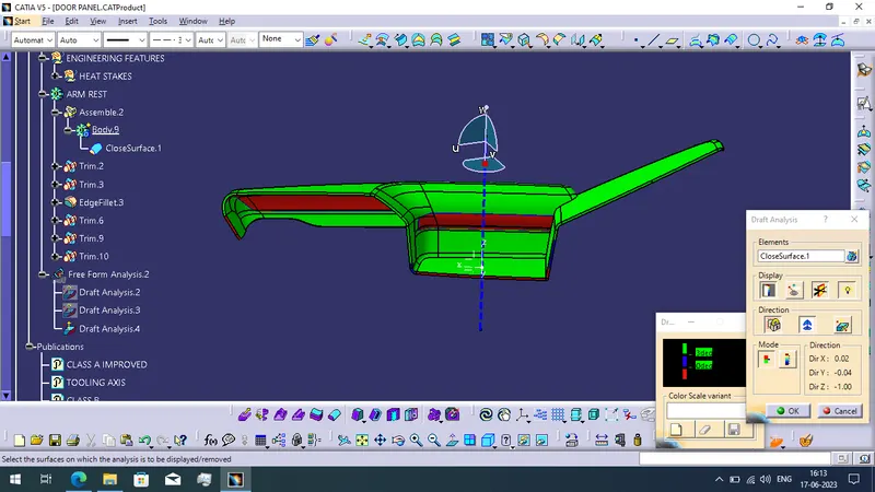
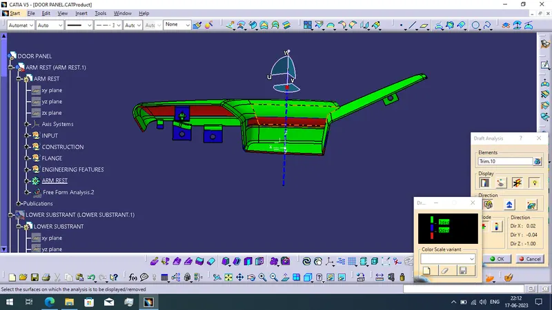
In the draft analysis report the green color is represent all the surface is 3 degree or more draft angle. The blue color is represent above 0 degree and below 3 degree draft angle. Red color indicate negative draft angle. So this negative draft angle surface patches are not good so we want to create the clearance axis.
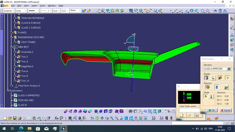
Clearing axis draft analysis report:
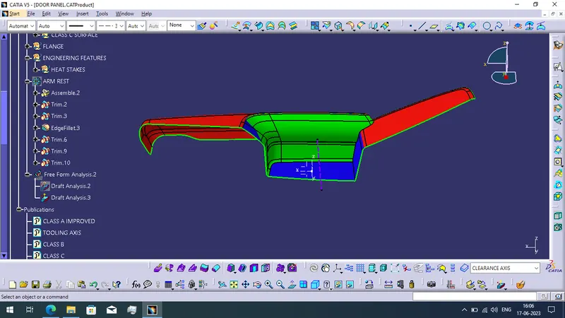
CREATING ARM REST SOLID COMPONENT:
DRAFT ANALYSIS REPORT OF ARM REST:
LOWER CONSTRANT:
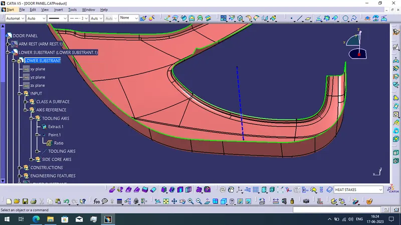
To create a solid body of lower constrant using the given class A surface.
Creating tooling axis of Lower Constrant:
- Extract the outer boundry curve as the reference of creating tooling axis.
- Using point command for point type 'on curve' and 0.5 ratio.
- Next we use the line command with point and direction option. Finally we create the tooling axis.
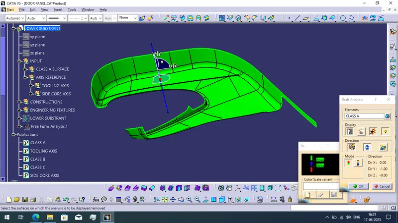
Draft analysis of Class A Lower Substrant surface:
All the green color surface patches are 3 degree draft angle or more draft angle.
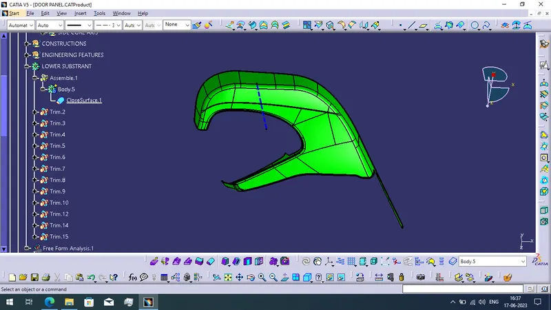
CREATING LOWER SUBSTRANT SOLID BODY:
- To create the solid body using the closed surface method.
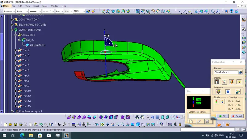
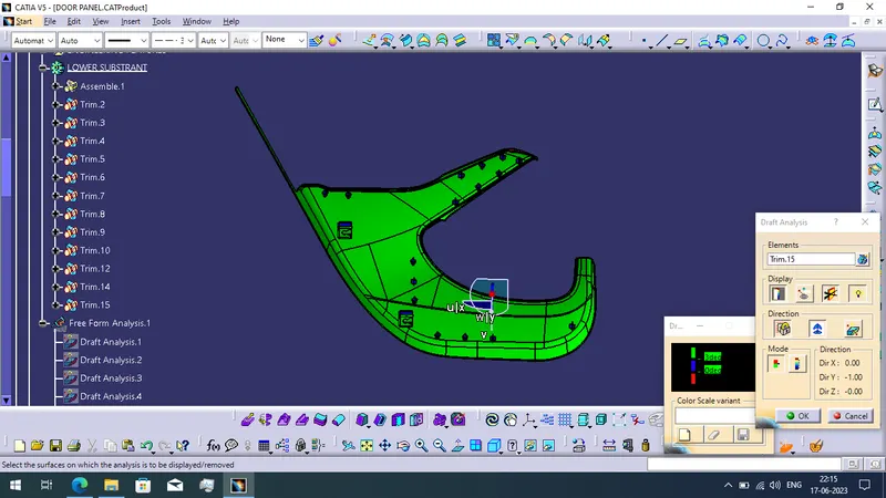
DRAFT ANALYSIS OF LOWER SUBSTRANT SOLID COMPONENT:
- All the inner body of the lower substrant have a 3 degree or more draft angle.
BOTTLE HOLDER:
To create a solid body using given Class A surface of Bottle Holder.
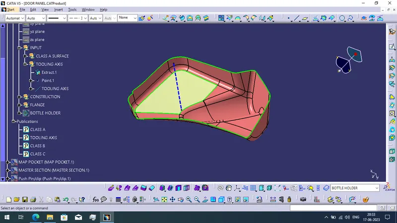
Creating tooling axis of Bottle Holder:
- Simply extract a one patch of the surface and then create the point using the point command of on surface point type.
- To use the line command with help of created point and the Y direction.
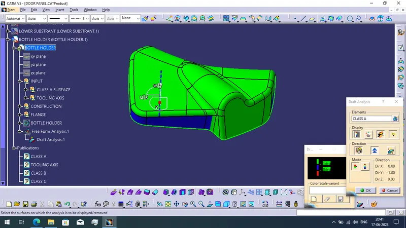
DRAFT ANALYSIS OF BOTTLE HOLDER CLASS A SURFACE:
- The green color indicate the draft angle of 3 degree or more draft angle.
- And the blue color is a minimum draft angle of 0 to maximum draft angle of 2.99.
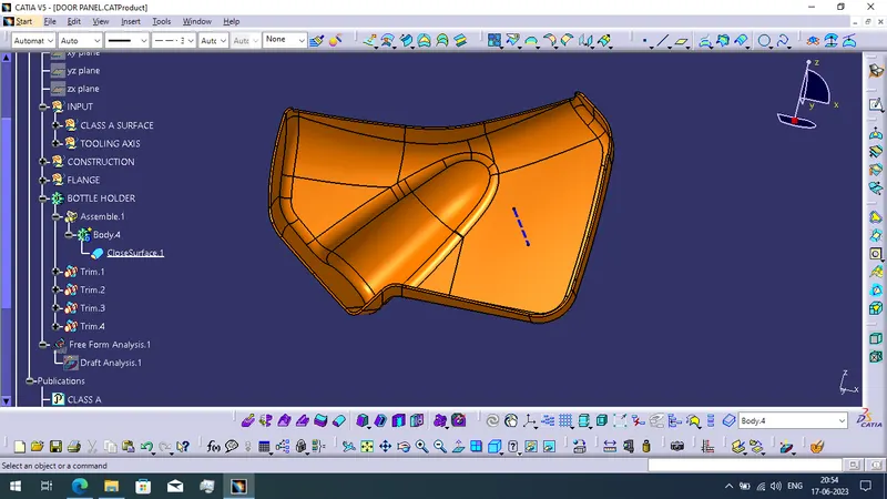
CREATING SOLID BODY OF BOTTLE HOLDER:
- To create the solid body using closed surface metho.
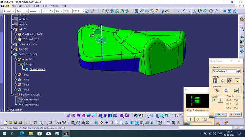
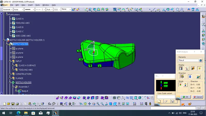
DRAFT ANALYSIS REPORT OF BOTTLE HOLDER SOLID BODY:
- The solid body of Bottle Holder is get to be draft analysis and green color of the surfaces are 3 degree or more draft angle and blue color indicates the draft angle of 0 to 2.99 degree.
MAP POCKET:
- To create the solid body of map pocket using given class A surface.
Creating tooling axis of Class A Surface:
- To extract the surface and use the point command to on extracted surface.
- To create the line using the point and Y direction.
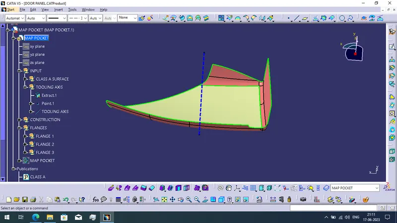
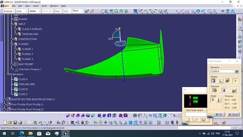
DRAFT ANALYSIS OF MAP POCKET CLASS A SURFACE:
- All the surface of the map pocket have a draft angle of 3 degree or more.
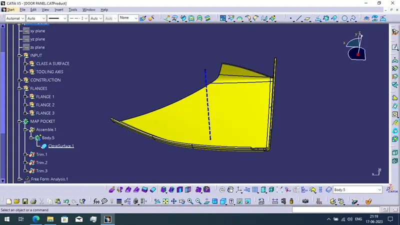
CREATING THE SOLID BODY OF MAP POCKET:
- To create the solid body of map pocket using closed surface method.
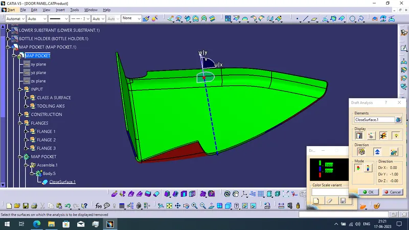
DRAFT ANALYSIS OF MAP POCKET SOLID BODY:
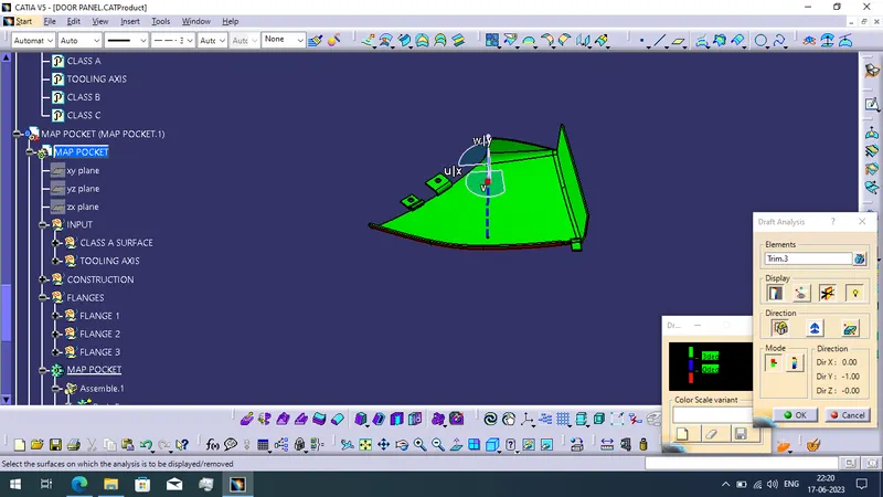
- In the draft analysis report the green color surfaces have a draft angle of 3 or more degrees. And the blue color is 0 to 2.99 degree draft angle. The red color indicates the negative draft angle.
CREATING ENGINEERING FEATURES OF THE DOOR TRIM PANEL COMPONENTS:
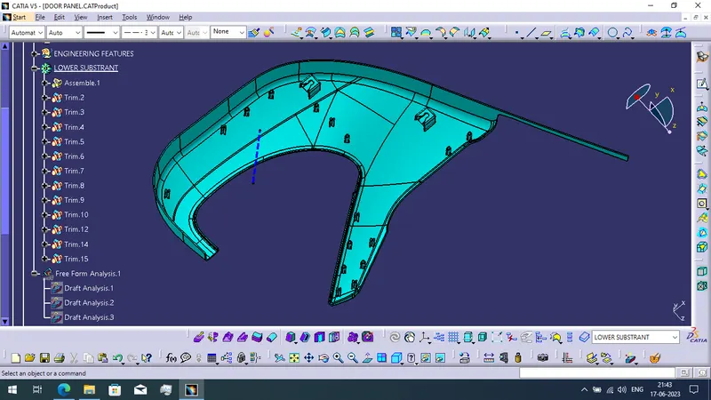
Creating Heat Stakes, Locators, and Dog houses on Lower Substrant:
- To create the Heat Stakes, Locators and Dog houses using the reference of the master section.
- The heat stakes are using to joining of two components.
- The locators are used to arrest the degree of freedom of the component.
- Dog houses are used to help reduce the height of the joining of two components.
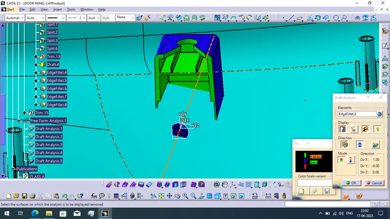
Draft Analysis of heat stakes:
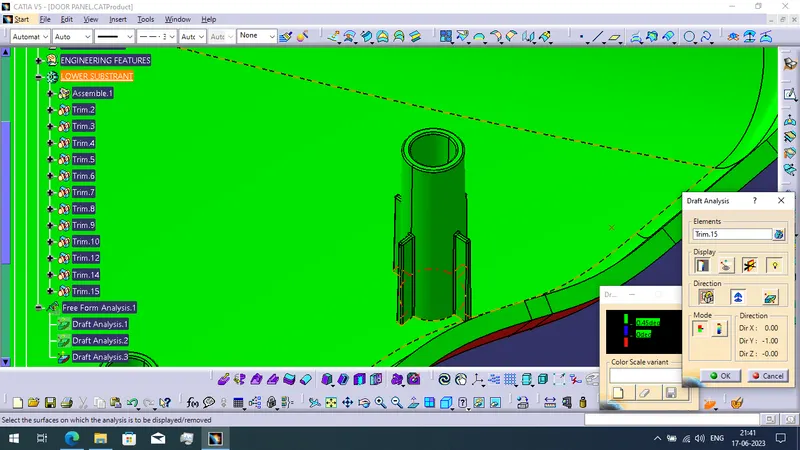
- The Heat stakes created by the draft angle of 0.5 degree. And the green color of the heat stake is indicating also the draft angle of the heat stake is less than 0.45 and more than 0 degree.
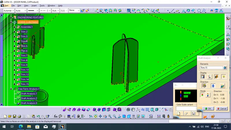
Draft anaysis of Locators:
- To creating of locators for the draft angle are also 0.5 degree.
- The draft analysis report is indicates green color for the draft angle of the locators are 0 to 0.45 degree.
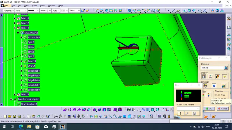
Draft analysis of Dog House:
- The outer surfaca of the dog house is given by 1.5 degree draft angle.
- Draft analysis report is indicating green color surfaces have maximum of 1.45 degree draft angle.
- Also the dog house have a side core draft analysis too.
- For the draft analysis report the inner side of the dog house is indicating green color of draft angle 0.45 degree.
FINAL COMPONENTS OF THE DOOR TRIM PANEL:
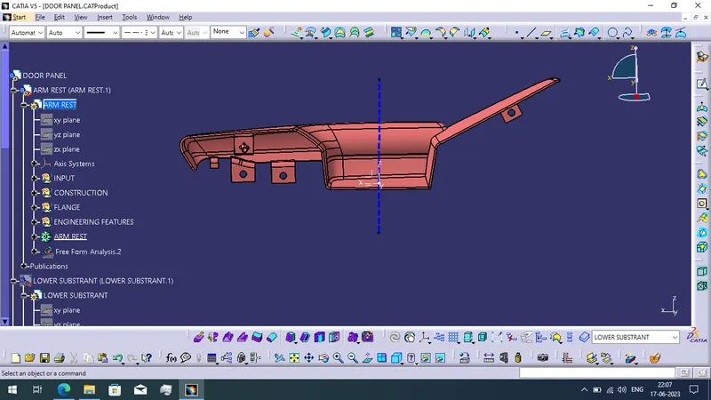
ARM REST:
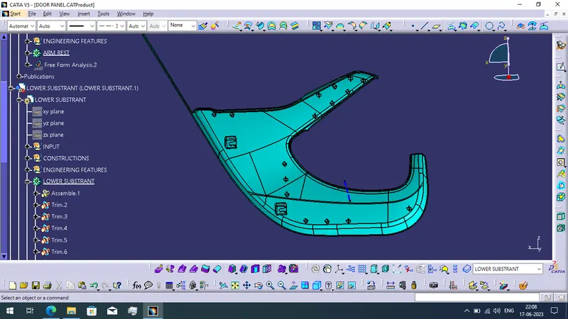
LOWER SUBSTRANT:
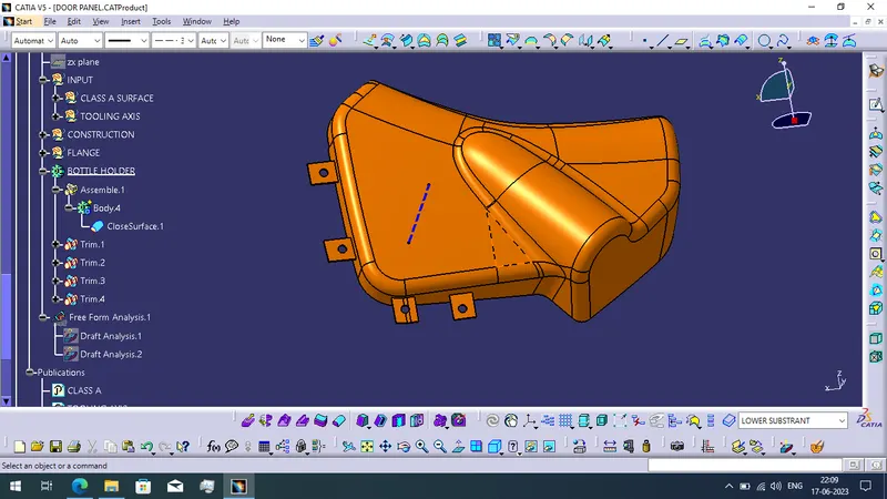
BOTTLE HOLDER:
MAP POCKET:
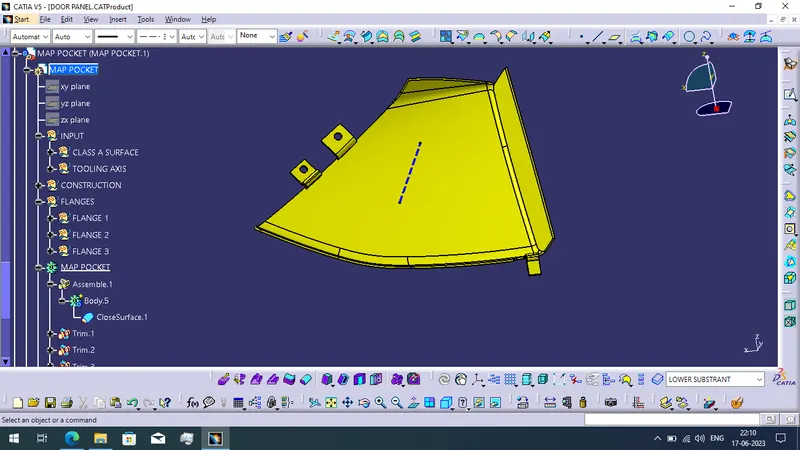
DRAFT ANALYSIS REPORT OF THE ALL COMPONENTS:
ARM REST:
LOWER SUBSTRANT:
BOTTLE HOLDER:
MAP POCKET:
FINAL ASSEMBLED DOOR TRIM PANEL:
CONCLUSION:
I have created the class B and class C surface using the given class A surface. Then converted surface into the solid body of 4 components. When i finished to create the solid body of the given class A surface then create the engineering and additional like dog houses, heat stakes, locators and flanges as a reference of master section. And add the push on the dog house. Final we get complete door trim panel product.