Week 12- Final project
Aim:-
The objective is to design the car door's inner panel based on the provided Class-A surface reference and incorporate the master section. Additionally, the task involves adding attachment features and conducting a draft analysis to ensure the manufacturability of the CATIA V5 part.
Objective:
-
Generating a product file using the provided Class A data, ensuring that all parts are separated individually.
-
Establishing the tooling direction for all components to facilitate the manufacturing process.
-
Constructing solid bodies by refining Class B and Class C surfaces to meet design specifications.
-
Adhering to the master section guidelines to craft flanges and incorporate engineering features accurately.
-
Implementing features for the final assembly process, incorporating additional information such as dog houses and heat stakes.
-
Conducting draft analyses on each component to assess manufacturing feasibility and ensure alignment with design requirements.
Introduction:
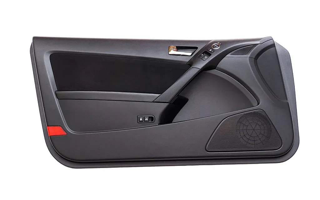
The inner door panel serves as both an aesthetic and functional element within an automobile. It functions as the interface between the car's interior and the inner workings of the door. Typically, an inner door panel includes components such as an armrest, map pocket, bottle holder, and a lower substrate. In contemporary automotive design and manufacturing, these panels are predominantly crafted from plastic materials like polypropylene and ABS. This choice of materials not only contributes to the panel's lightweight nature but also enables the creation of intricate and complex shapes, enhancing both the design and functionality of the door panel.
Draft Analysis:
Draft analysis is a vital technique used in CATIA V5 to assess the manufacturability of a part model based on the applied draft conditions. Its primary objective is to ensure that the part can be effortlessly removed from the mold during the manufacturing process.
In manufacturing, it's crucial to avoid designs with straight 90-degree profiles from their base surface, as these parts cannot be efficiently ejected from the mold. To resolve this, a slight draft angle is strategically applied to every area of the component, facilitating its smooth removal from the tool.
The concept involves specifying a preferred direction in which the component should eject, ensuring a seamless extraction from the mold. In essence, draft analysis determines whether the model incorporates a draft angle and quantifies its magnitude concerning the tool's ejection direction.
Procedure for Draft Analysis:
-
Start by examining the continuity of the given Class A surface.
-
Investigate three directions (X, Y, and Z) and determine the most suitable direction for mold production.
-
In cases where the faces along the Z-axis are either positive or negative, designate the Z-axis as a dummy tooling axis.
Tooling Axis Creation:
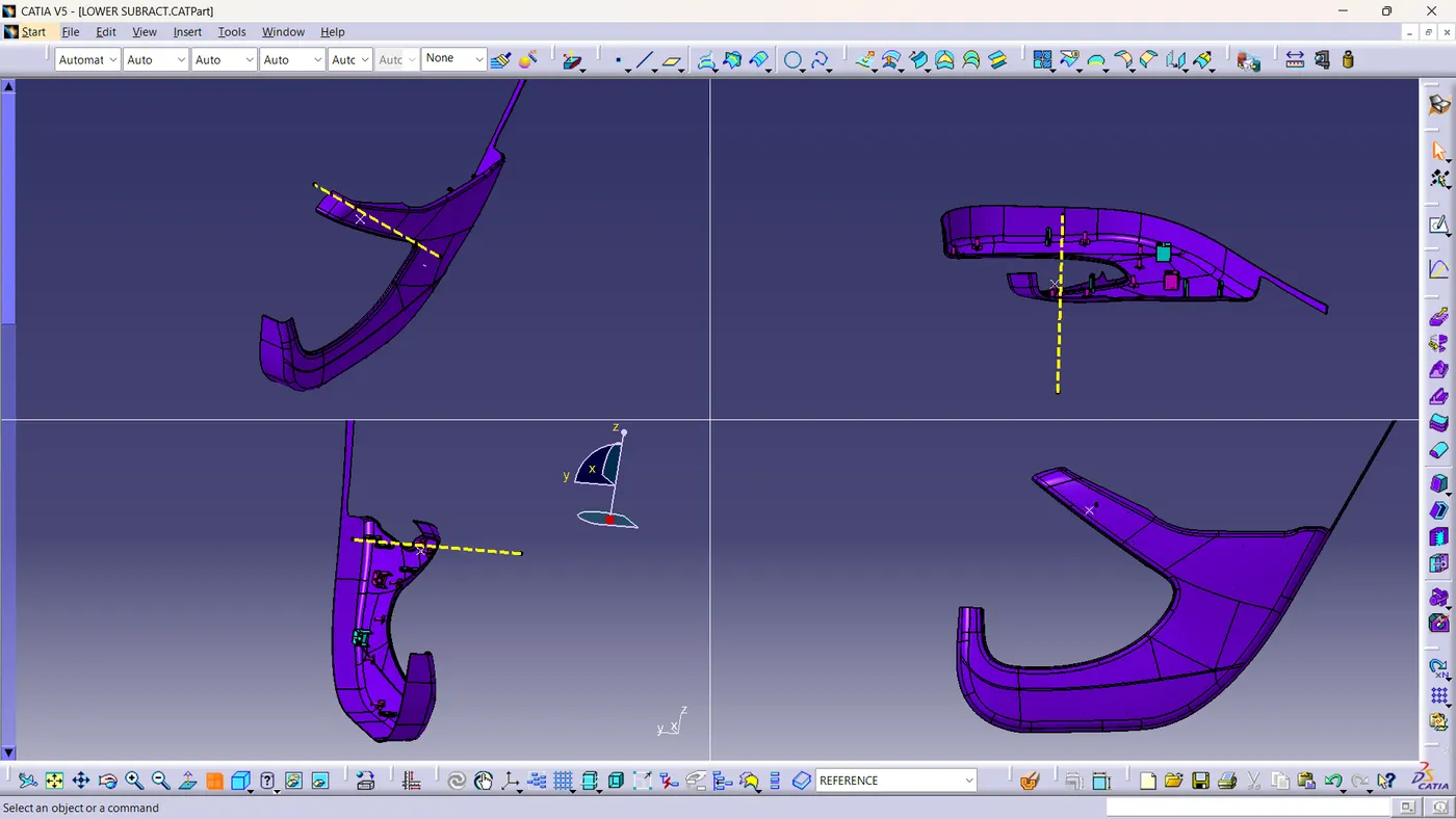
The tooling axis corresponds to the direction in which the mold or cavity opens.
- Create a point at the center of a hole.
- Establish an axis system on this point.
- Generate an intersection line along the ZX plane on the Class A surface.
- Extend the line to define the tooling axis for the model.
Draft Analysis Method:
- Access the draft analysis tool via "Insert > Analysis > Feature > Draft Analysis."
- Select the compass icon within the draft analysis dialogue box.
- Drag the compass and align it with the tooling axis.
- Opt for the "Draft Direction" option.
- Switch to quick analysis mode.
- Observe whether the surfaces conform to the specified draft angle criteria.
By following this systematic draft analysis process, manufacturers can ensure that their designs are conducive to efficient manufacturing processes, including smooth part ejection from molds.
Door inner panel components:
- ARM REST
- BOTTLE HOLDE
- MAP POCKET
- LOWER SUBSTRATE
- ARM REST
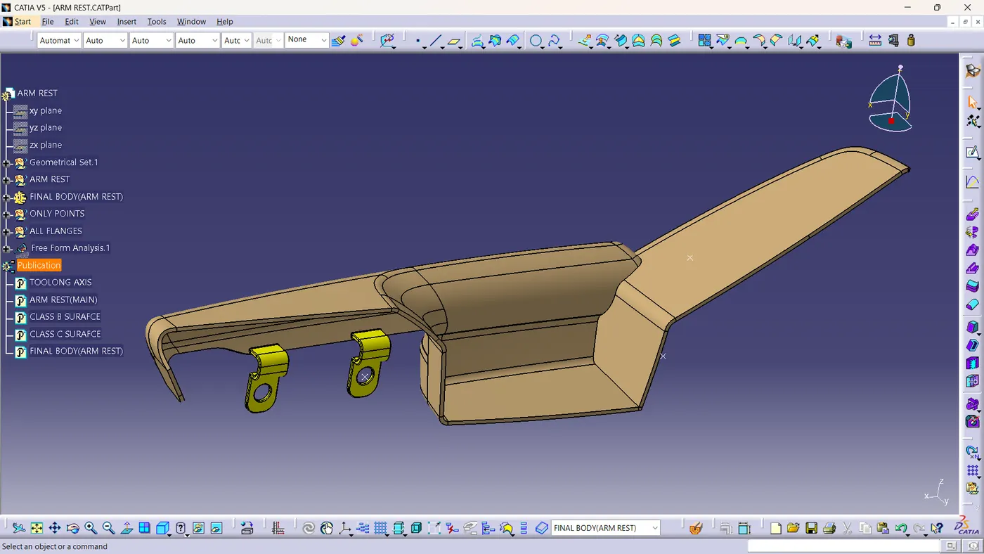
Class A surface and draft analysis:-
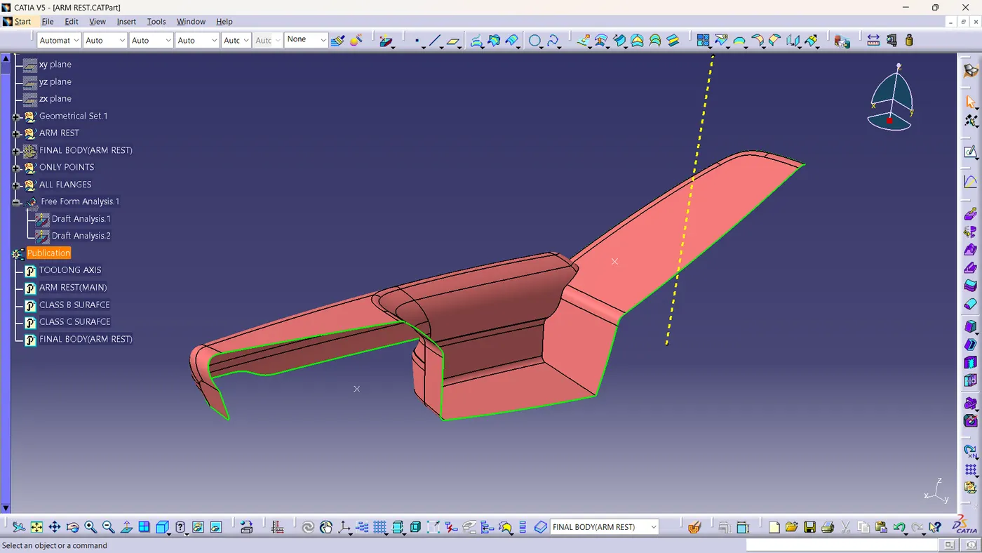
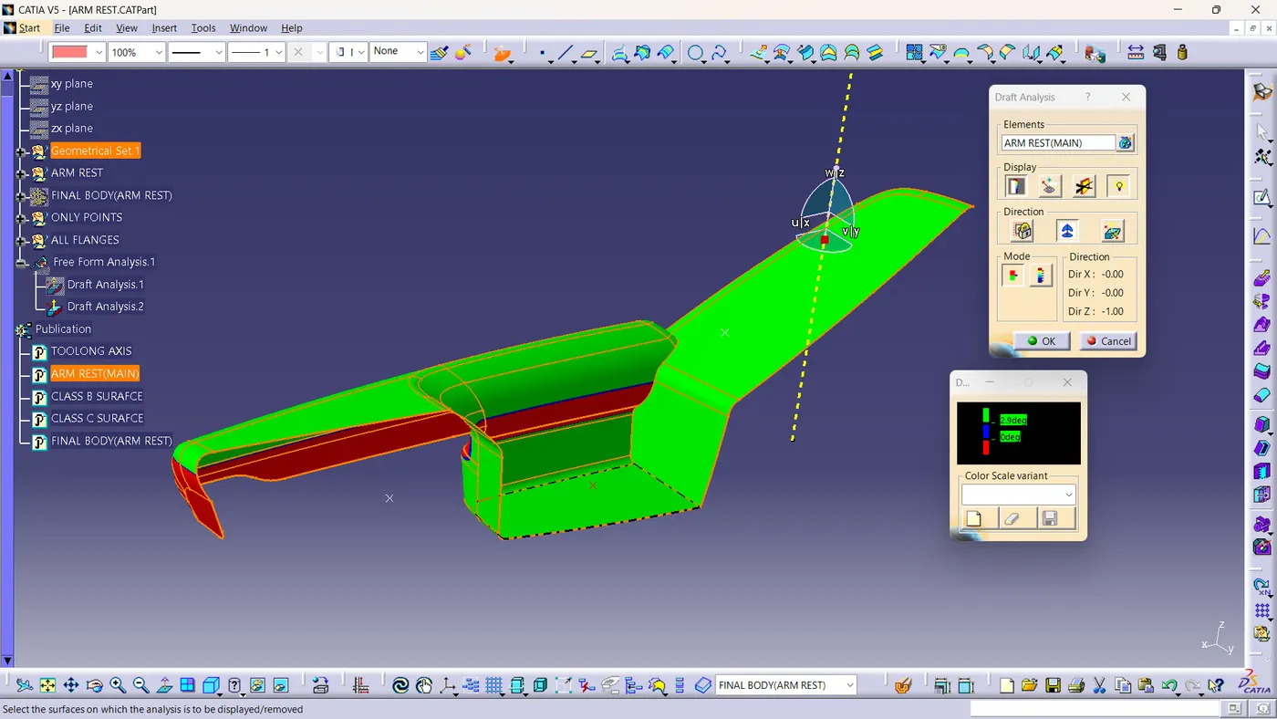
*NB:The given class A surface have negative draft angle, for the further modifiacation coordinate with class A creation engineering team.
PLASTIC PART WITH ENGINEERING FEATURES:
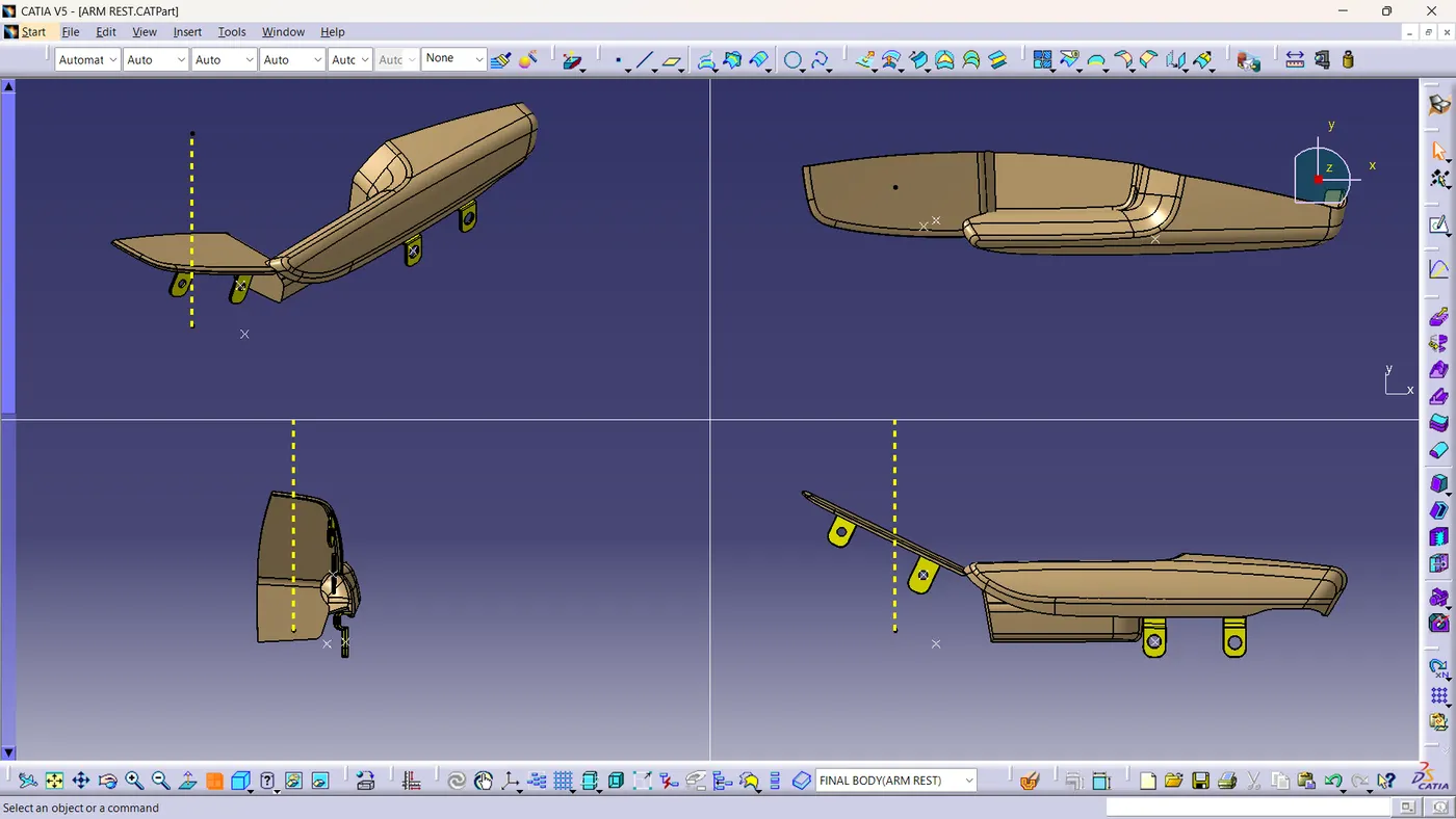
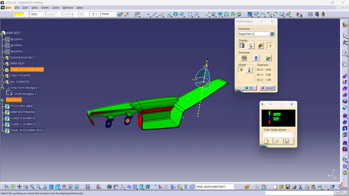
2.BOTTLE HOLDER
A surface and draft analysis of surface A:-
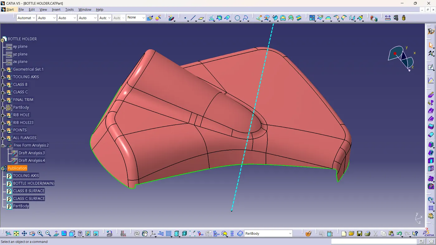
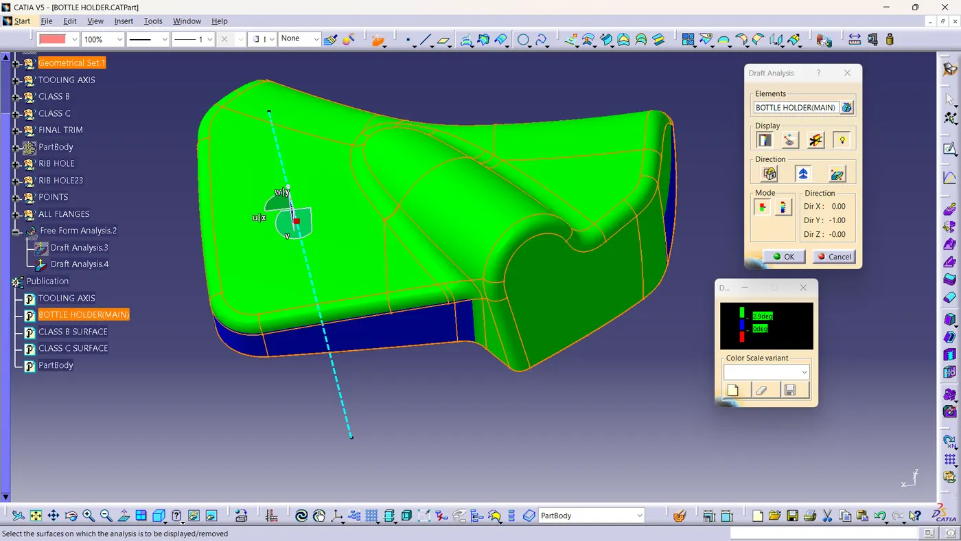
Final body all view and draft analysis:-
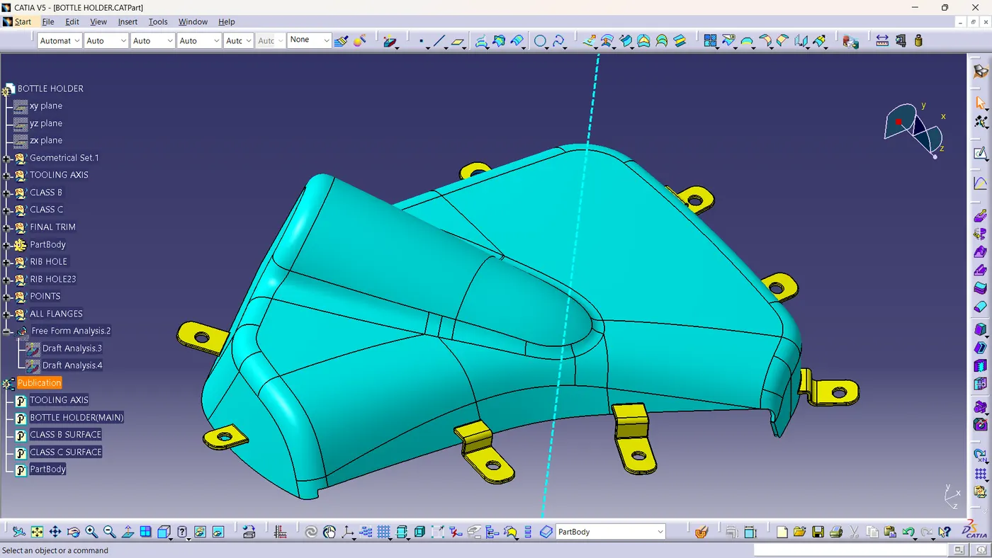
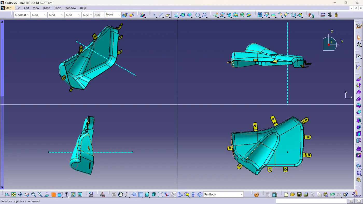
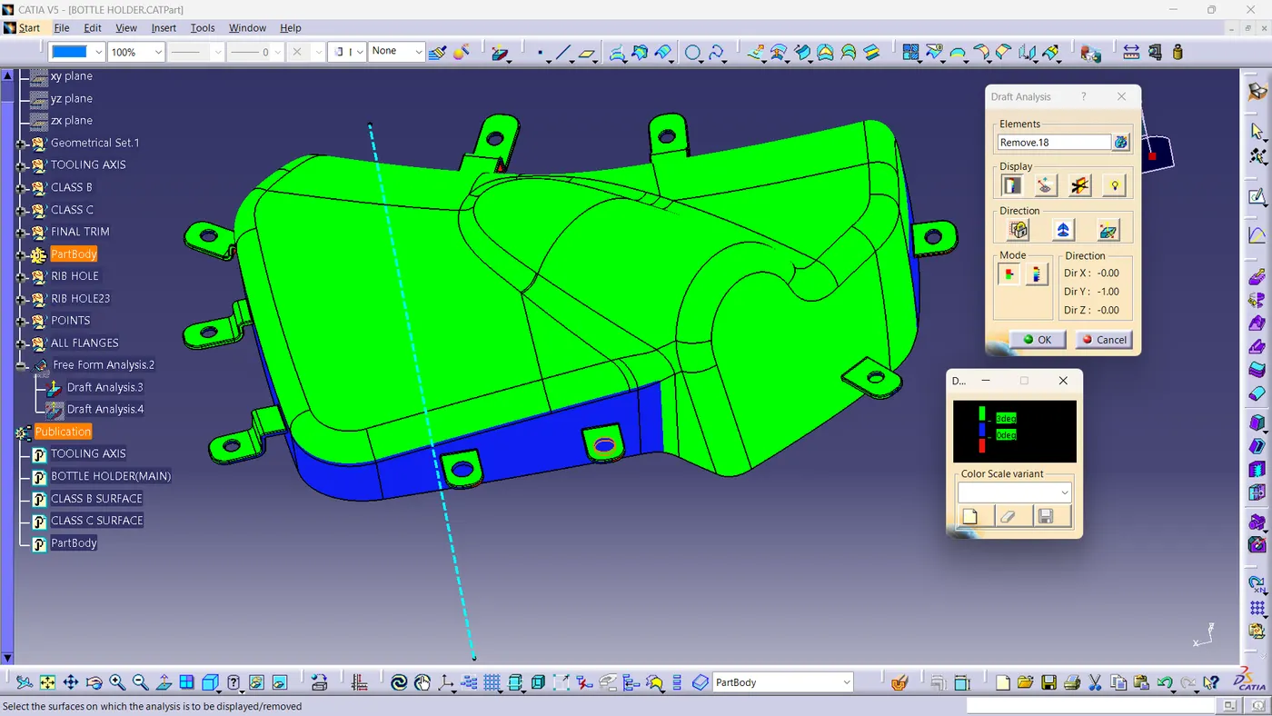
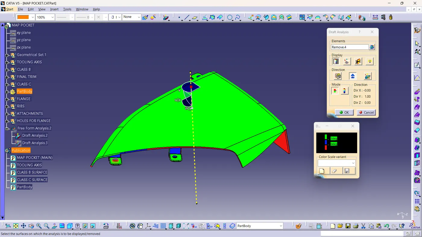
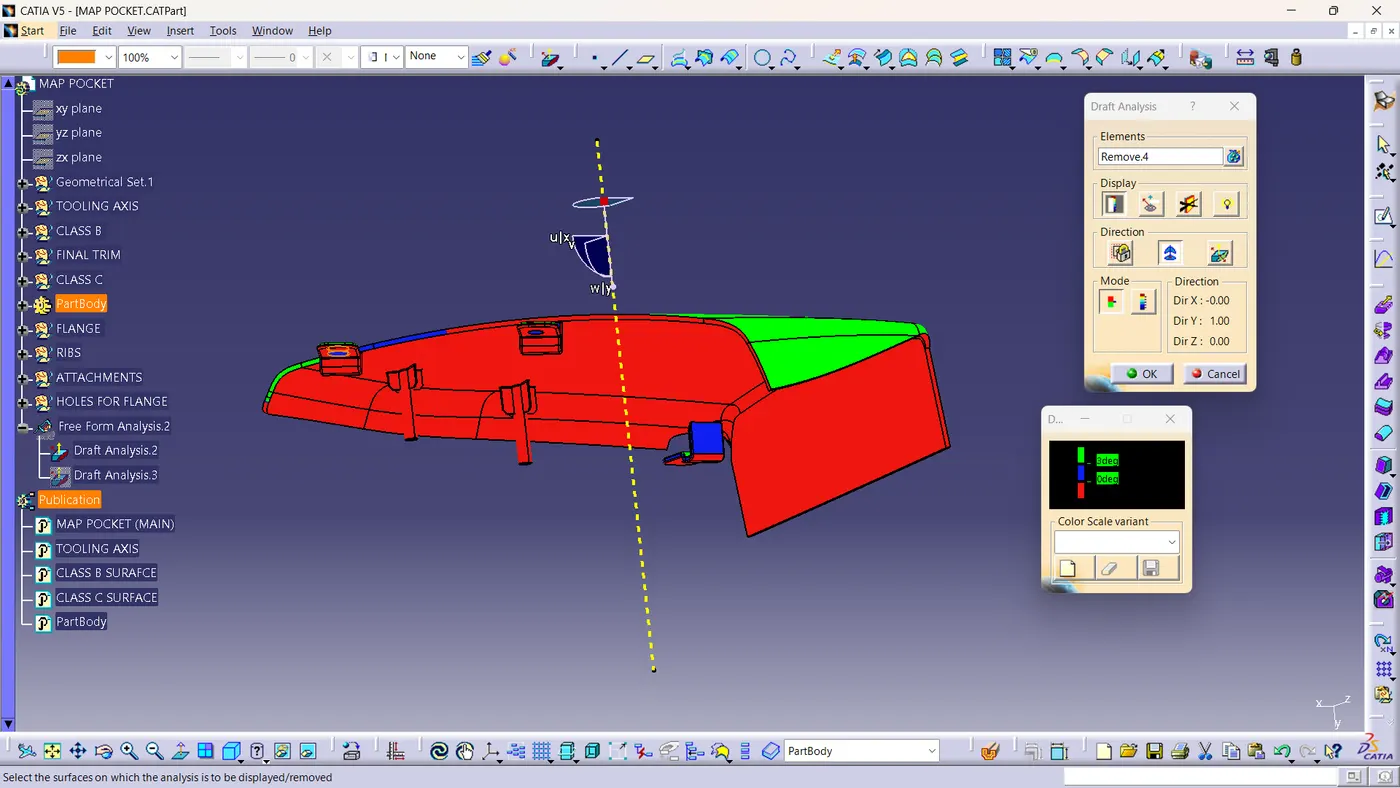
3.MAP POCKET
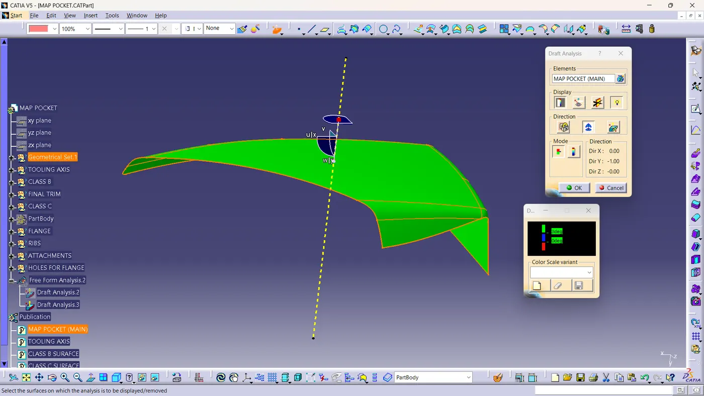
Class A surface view and draft analysis:-
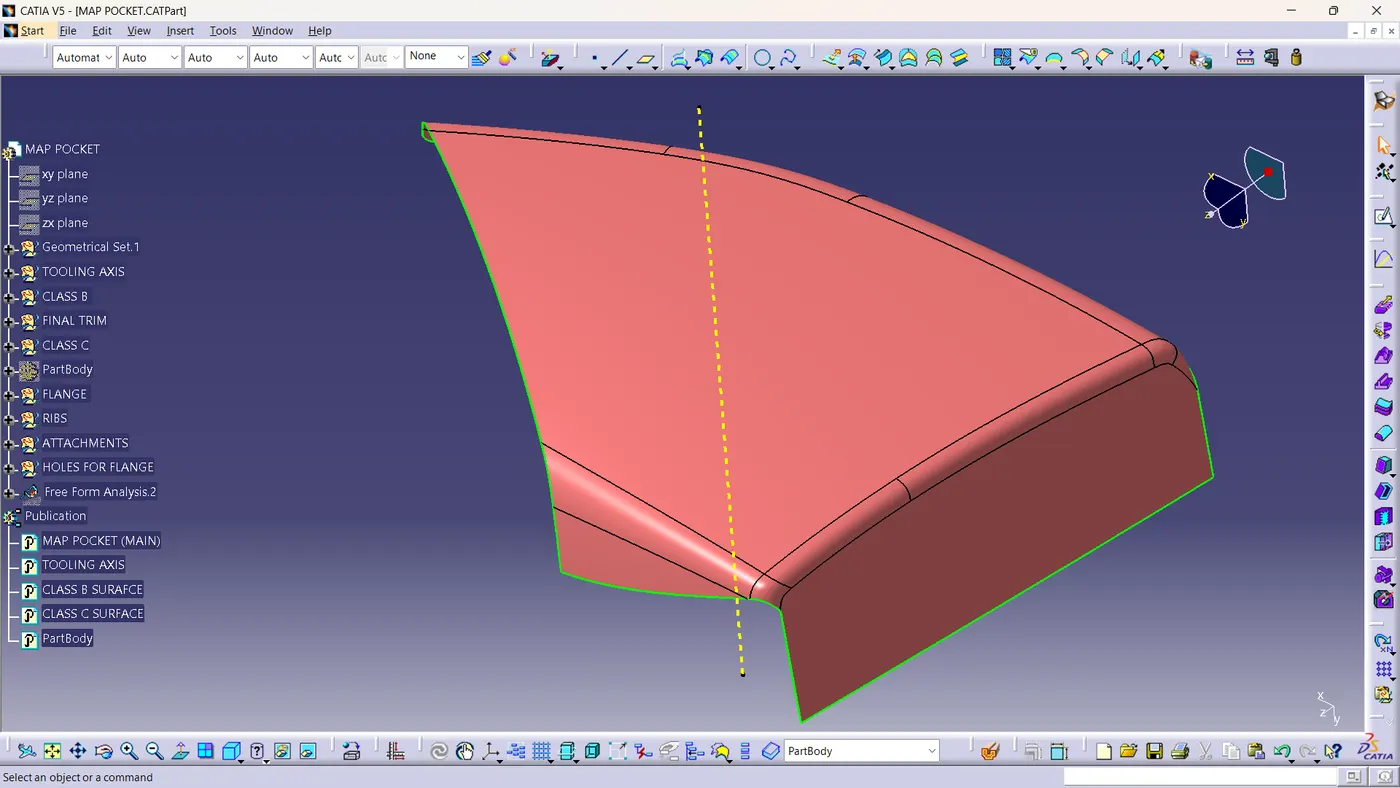
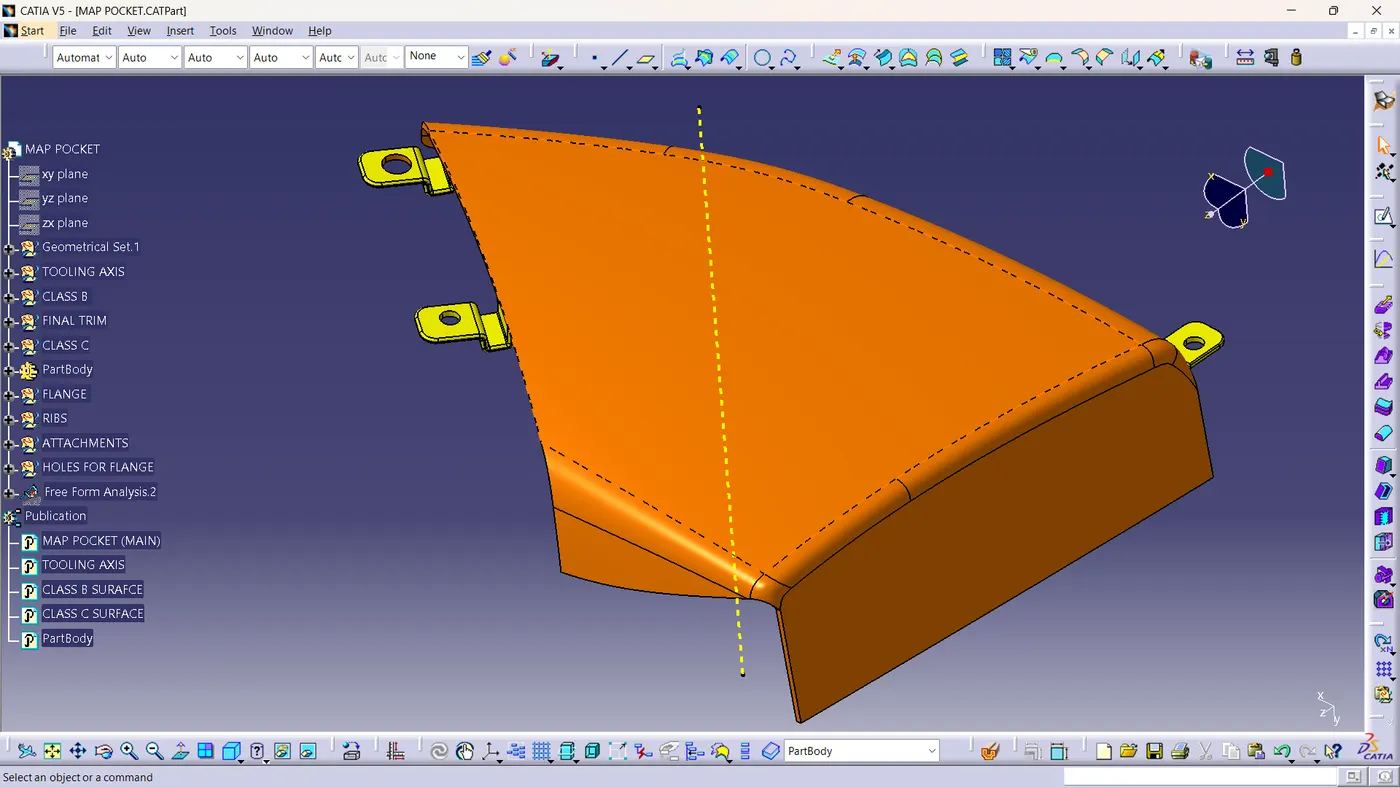
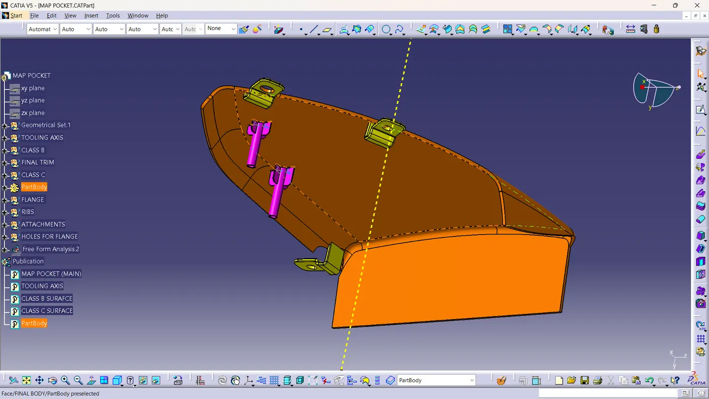
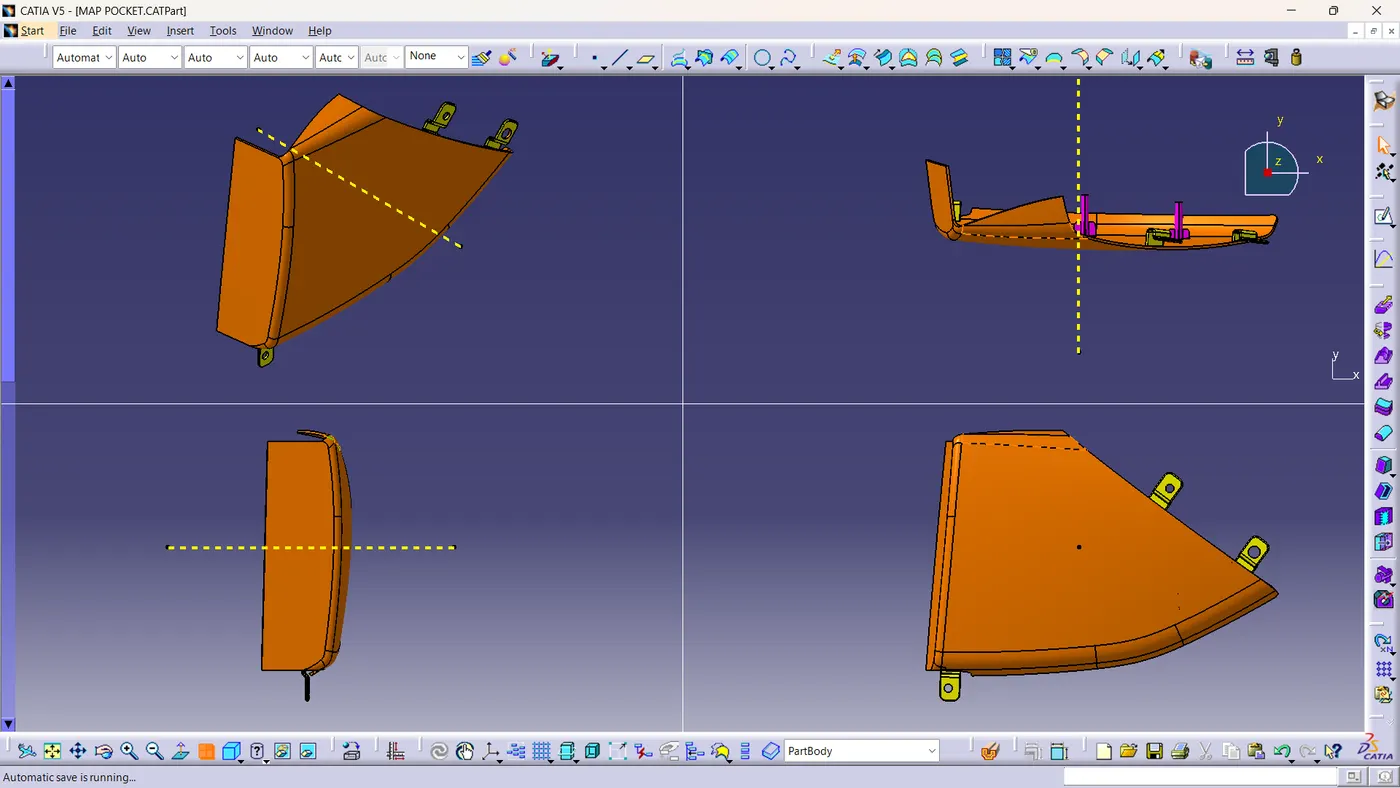
Final body and draft analysis
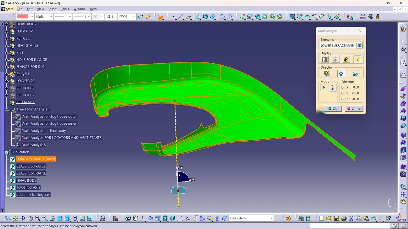
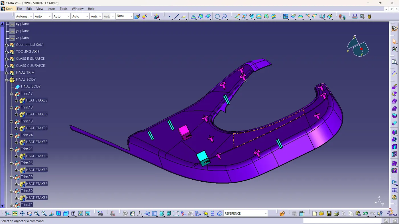
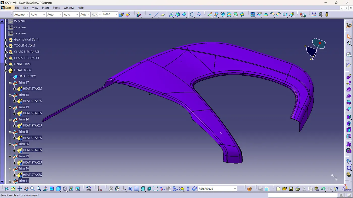
LOWER SUBSTRATE
Class A surface and draft analysis:-
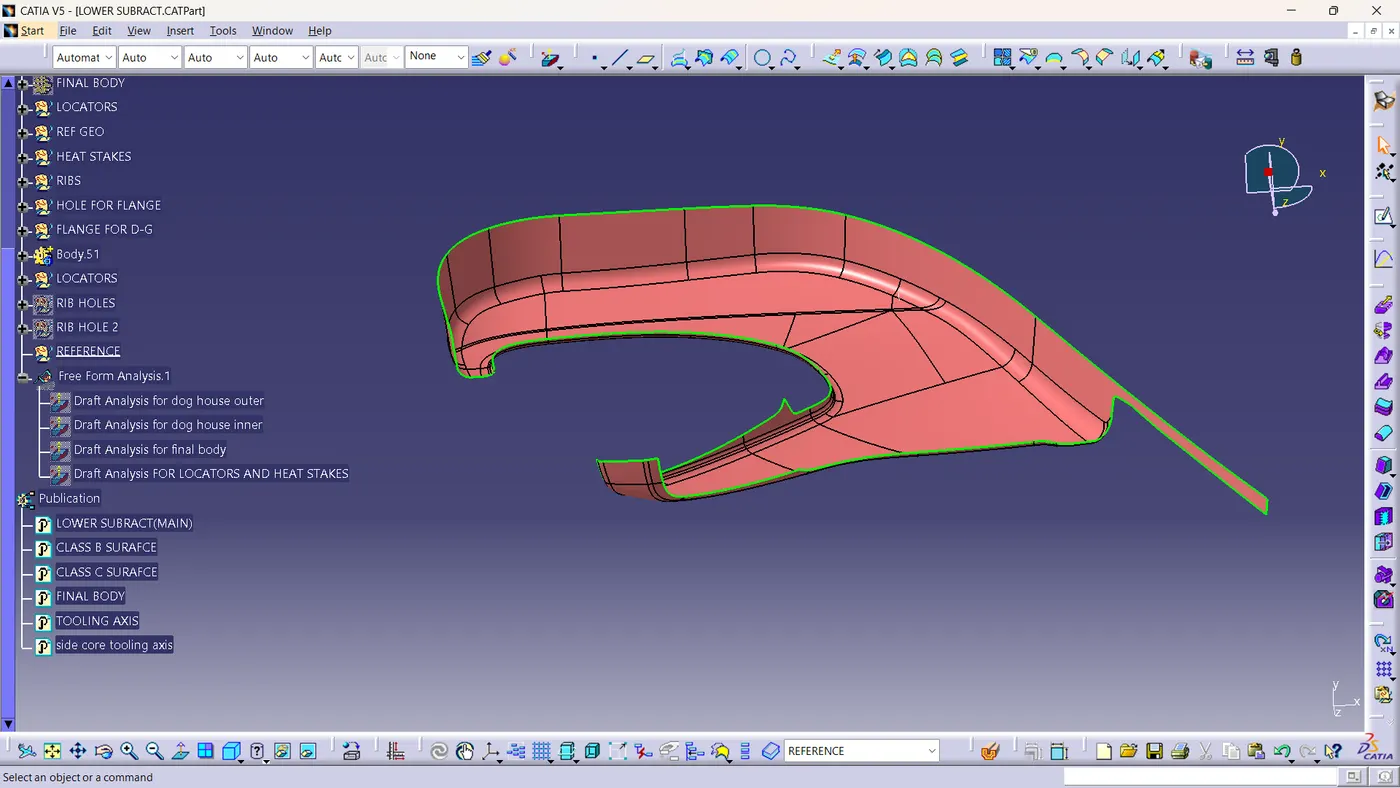
Final body view:-
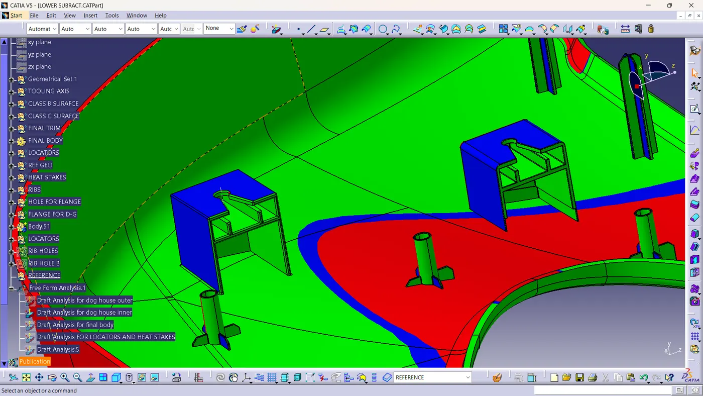
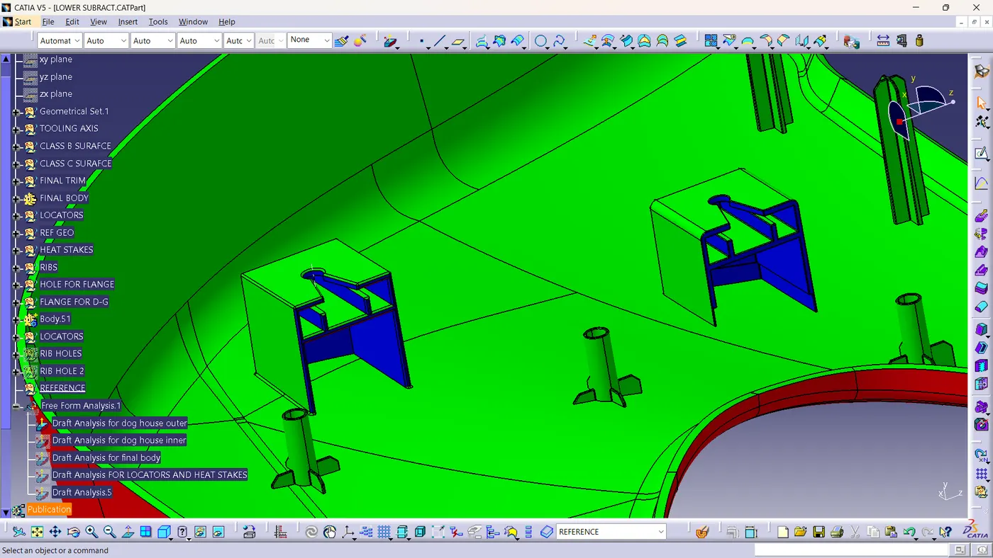
Draft analysis for dog house outer:-
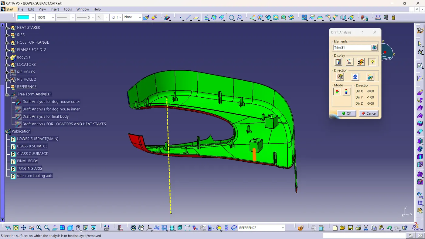
Draft analysis for dog house inner:-
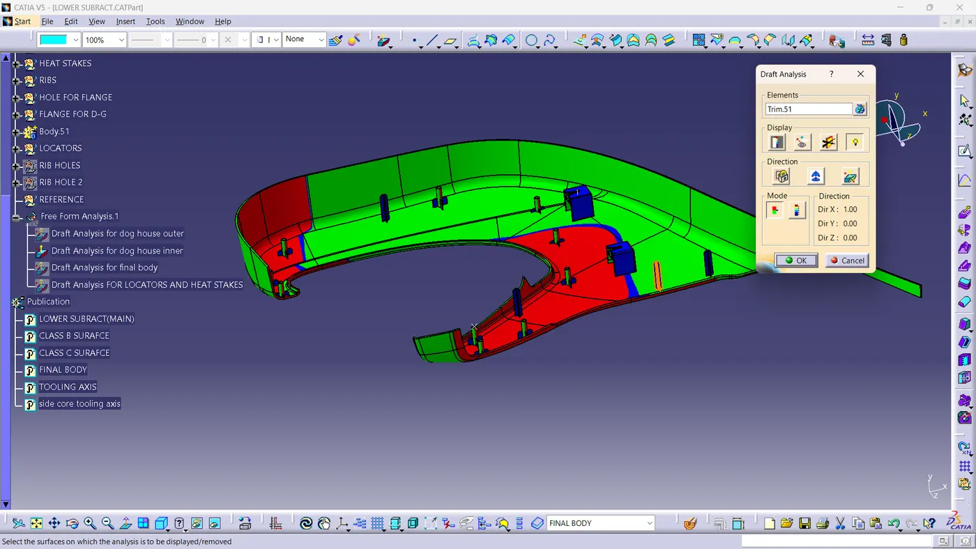
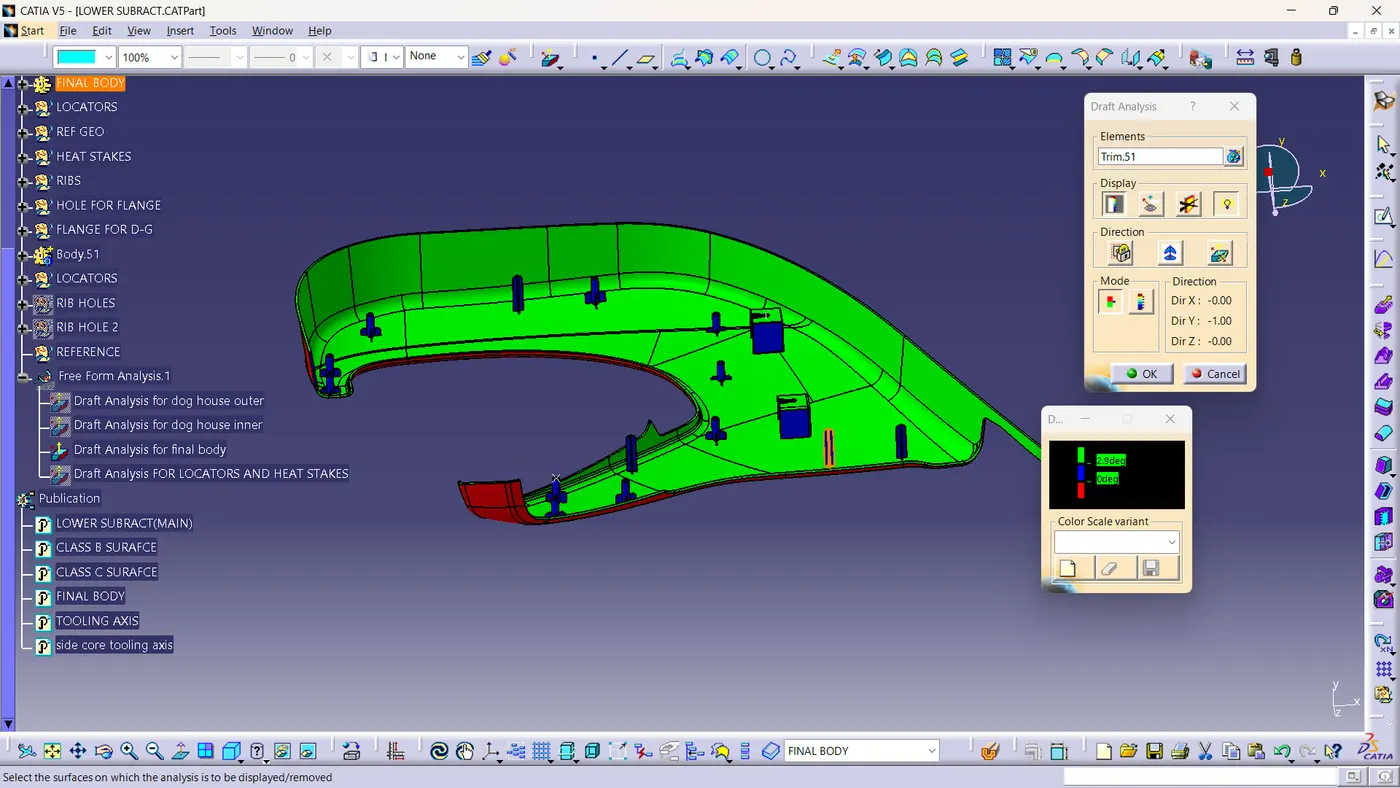
Draft analysis for final body:-
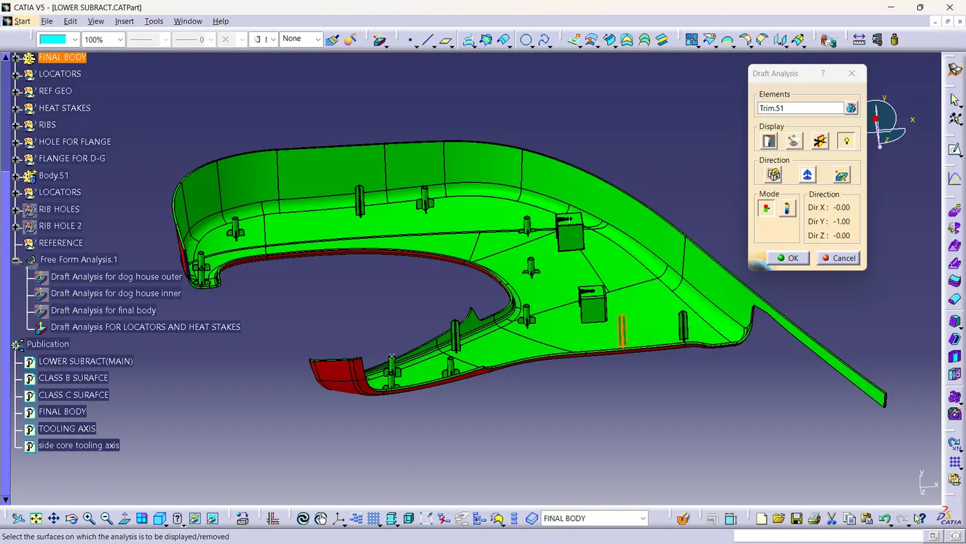
Draft analysis for locator and heat stakes:-
ENGINEERING ATTACHMENT FEATURES:
Dog House:
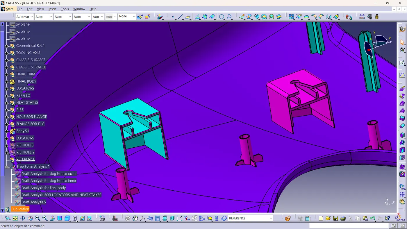
A "dog house" is a critical engineering feature designed to address the issue of sink marks that can form on a Class A surface during the creation of attachment features on a Class B surface. Sink marks are depressions or imperfections that can occur when there is uneven cooling or pressure distribution in the molding process, leading to cosmetic defects on the final product.
Flanges:
Flanges are integral joining features employed to assemble distinct components. To craft these flanges, the master section technique was employed. Initially, a single flange was fashioned, serving as the prototype. Subsequently, an axis-to-axis system was applied to replicate and position these flanges accurately.
In order to optimize their manufacturability, a draft of 0.5 was incorporated into the flanges, enhancing their ease of removal from molds during production. Furthermore, a specific gap of 60-100 mm was strategically maintained between adjacent flanges, ensuring adequate spacing and functionality.
To further enhance the versatility and utility of these flanges, boolean operations were deployed. These operations allowed for the seamless addition of attachment features into the closed body, expanding the functionality and adaptability of the assembled components. The resulting design incorporates both structural integrity and ease of manufacturing, making it a valuable element in various engineering applications.
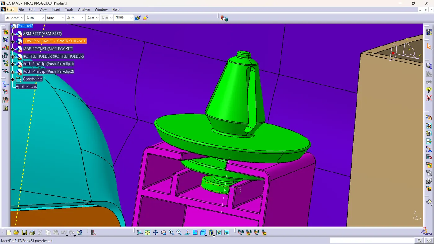
Push Pin Clips:
Push pin clips are essential components used for securely joining one component to another within a larger assembly. These clips play a pivotal role in ensuring that various parts or elements come together seamlessly and remain securely fastened.
Heat Stakes (Thermoplastic Staking):
Heat staking, also referred to as thermoplastic staking, is a specialized manufacturing process employed to join two dissimilar materials together, typically involving thermoplastic components. This innovative technique leverages localized heating and cooling to alter the temperature of plastic components, enabling the reshaping or reforming of these materials.
The advantages of heat staking are as follows:
- Simplications of the machinery
- Reduced cost of machinery.
- Multiple fastening point.
- Allows higher density of welds compared to hot air, cold form or ultrasonic welding.
Ribs:
Ribs are structural features incorporated into a part's design to enhance its stiffness and durability without the need to increase the overall thickness of the part. These ribs are strategically placed to provide reinforcement, preventing deformation or flexing, and ultimately contributing to the part's mechanical strength and resilience. Ribs are commonly used in various applications, such as in the automotive industry for reinforcing panels or in consumer products to improve the rigidity of thin-walled components.
Locators:
Locators are essential elements designed to facilitate the precise alignment of parts that need to mate or fit together within an assembly. These components are strategically placed to ensure that the parts align correctly, making the assembly process more straightforward and reducing the chances of misalignment or errors during manufacturing or assembly. Locators play a critical role in achieving the desired fit, function, and overall quality of the final product, particularly in industries where precision and accuracy are paramount, such as aerospace, automotive, and electronics manufacturing.
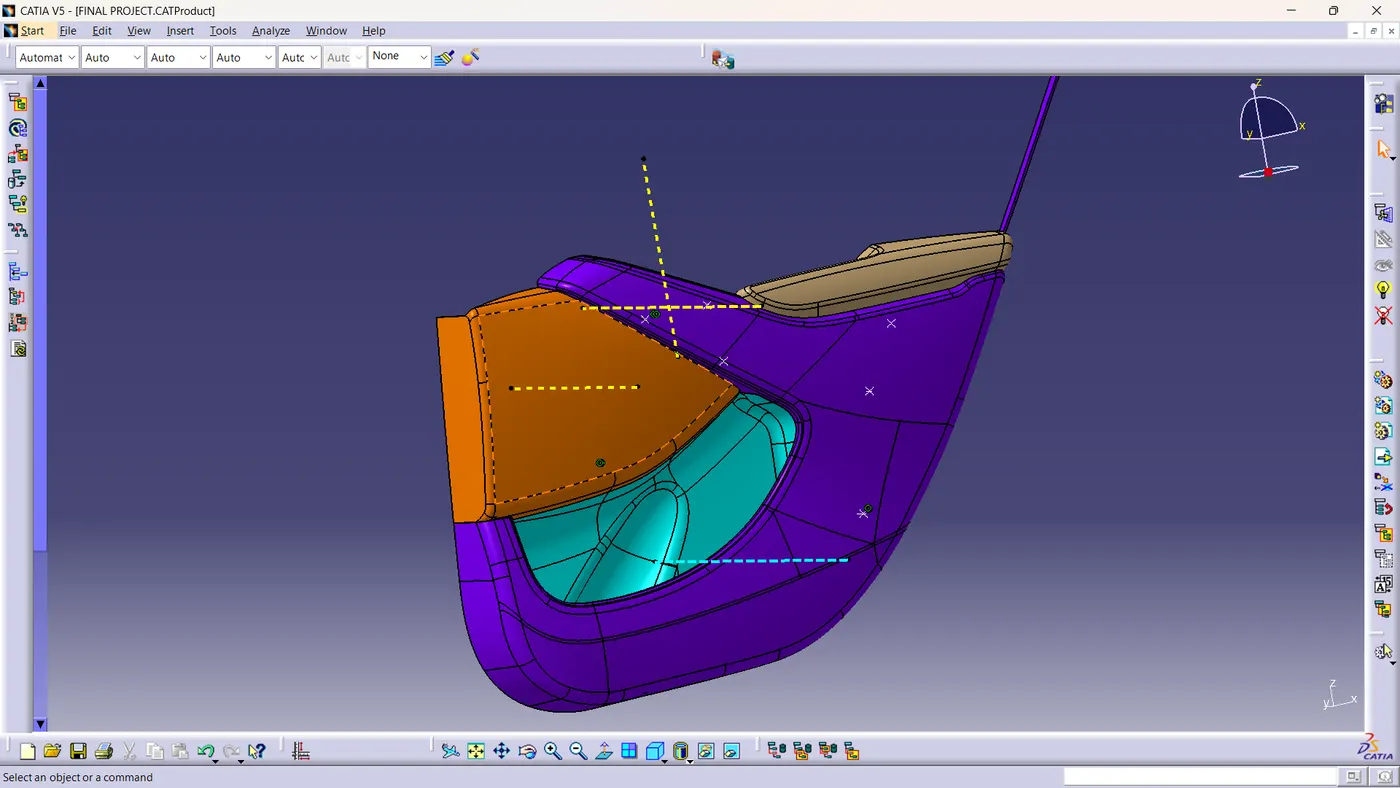
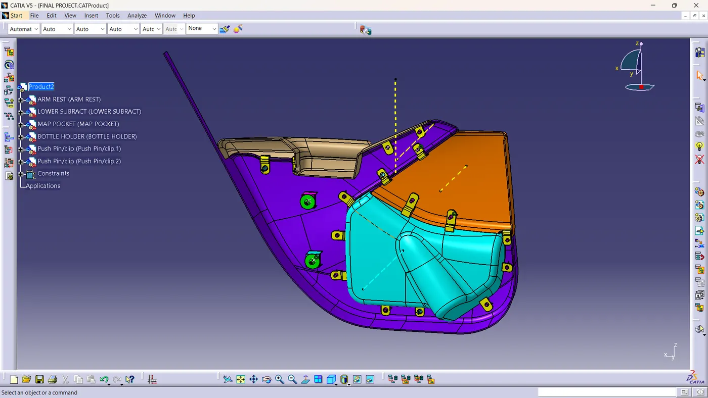
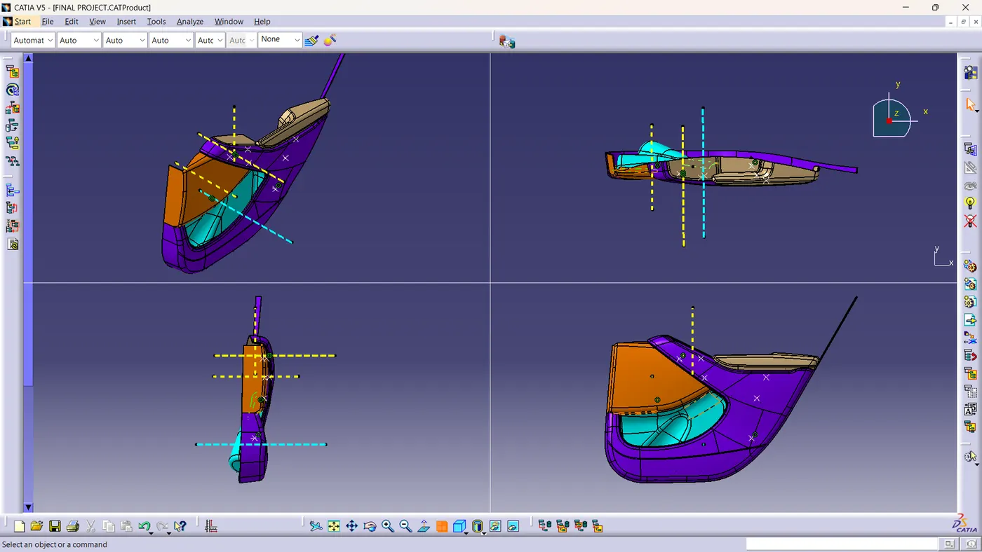
Assembly of door :-
Conclusion:
In the production of the Door Trim, we adhered closely to OEM (Original Equipment Manufacturer) guidelines and standards. This meticulous approach was executed through the utilization of the Part Workbench and Generative Shape Design Workbench within the CATIA V5 software platform. By following these established protocols and harnessing the power of cutting-edge design tools, we ensured that the Door Trim not only met but also exceeded the rigorous specifications and expectations set by the OEM. This commitment to precision and quality is a testament to our dedication to delivering top-tier products in accordance with industry-leading practices.