Week 12- Final project
Objective:
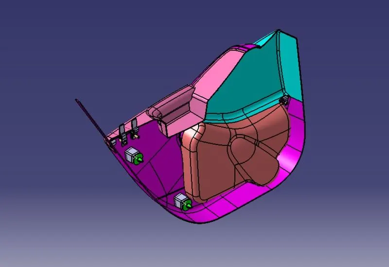
The main objective of this project is to develope the Door Trim panel by using the Class A Surface and the master sections which was given in the input file.
Creation of CAD model considering following inputs as like in OEM and tier1 companies
- a) Class A surface
- b) Nominal thickness : Refer master sections
- c) Attachment strategy :
Find a attachment strategy for the door panel complete work.
Use Push pin with Dog house for Lower substrate – Door panel attachment
Use heat stakes for part to part attachment.
GIVEN INPUT
Product Life cycle
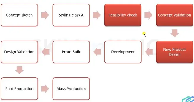
On a broad spectrum, the automotive design process can be split up into four stages:
- Concept
- Sketch
- Class A Surface (CAS)
- Computer-Aided Design (CAD)
An automotive vehicle concept is first hypothesized or envisioned by an artist, designer, or engineer, which is then sketched onto a paper. Once an idea is approved, it moves on to the computer where it is rendered in 2D.
Then, the Class A Surfaces are built. This is followed by a complete 3D CAD modelling of the automotive vehicle, including photorealistic renders, which later goes into mass production.
On a higher level, the product development process can be summarized as follows:
- Styling theme and approval CAS
- Preliminary design
- Preliminary analysis
- Final style approval
- Detail design
- Verification
- Development
- Prototype build
- Design validation
- Plot production
- Launch and mass production
Concept Sketch: Pre hand drawing done on a paper later converted to styling Class A which is basically done by software like ALIAS.
Design validation determines whether the design fulfills the intended purpose
Feasibility check is to determine the practicability of a design.
Concept validation is the stage of validating the design and possibility.
Before mass production any corrections will be corrected.
DESIGN LIFE CYCLE
It Involves
Concept sketches
Class A creation
Clay modeling
NPD CAD
Concept sketches which are fed into computer as 2D sketches
Class A: The dedicated Class A Surface creation software helps turn a sketch into a surface that can be controlled in a three-dimensional virtual space. One would typically require three images, i.e., the front view, side view, and top view.
Class A and clay modeling are inter related. Clay model is the one to one model of vehicle both interior and exterior would be made for realistic display.
NPD CAD – New product development is where the designing parts for assembly with dimensions takes place.
Now we are going to work in new product development phase for the given Input.
Materials details
Interior Trims are manufactured by Poly propylene (PP), Acrylonitrile butadiene styrene (ABS), Poly vinyl chloride (PVC).
Since plastic in light in weight, economic effectiveness wide variety of plastic are used. It also gives good aesthetic surface.
Input:
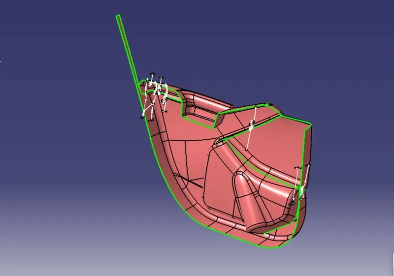
From the above input we are having the 4 class A Surfaces and the master sections to determine their thickness and the flange creation.
LOWER_SUBSTRATE:
Class_A_Surface:
First we want to check whether the Class A has any errors in it, if it has any errors on it then we want to work for immproving the Class A surface. After improving the A surface, later we can move to next work on it.
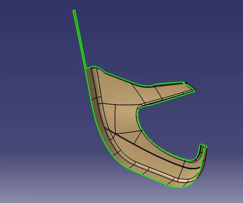
Tooling_Axis:
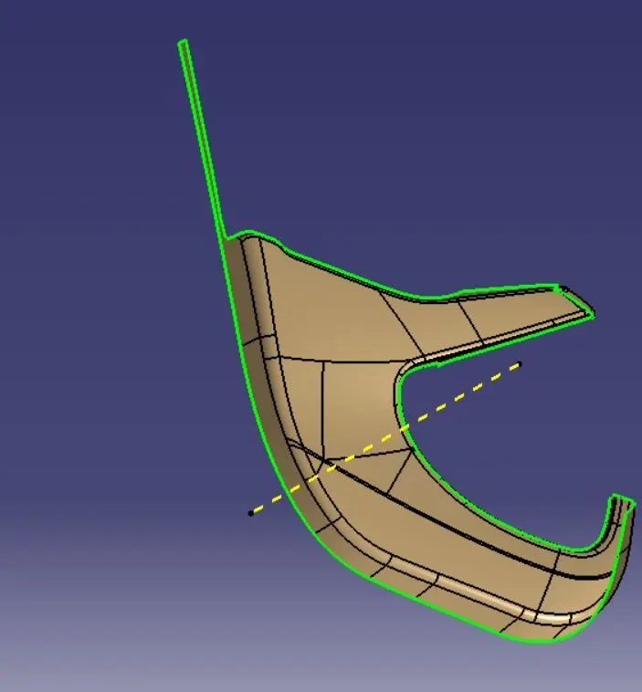
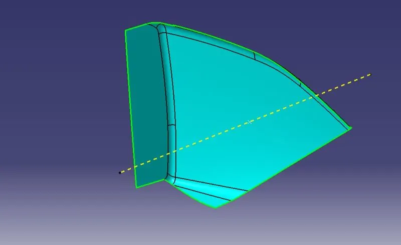
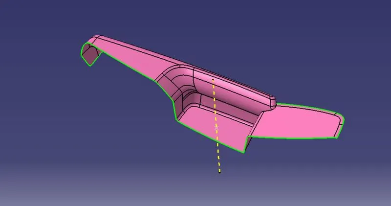
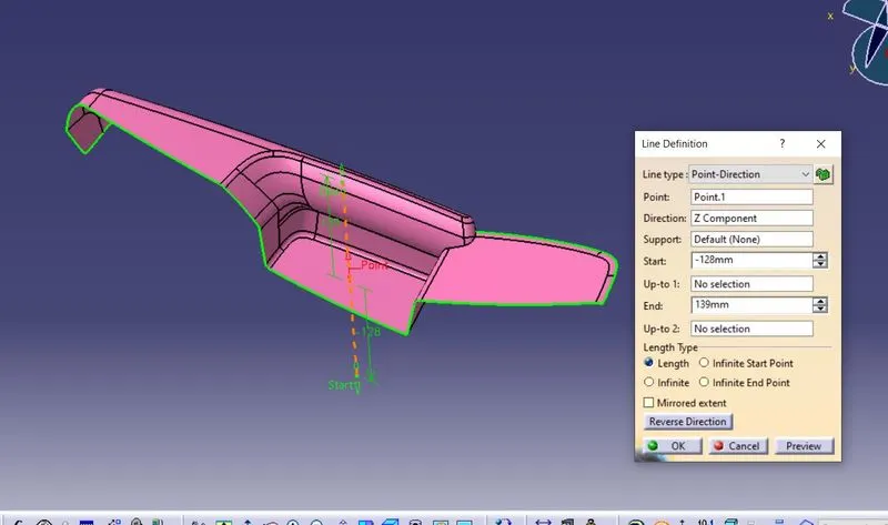
Tooling axis is the direction in which the mold opens and closes. Also the areas which need to be drafted. To find the tooling axis analyze the part like walls and find the possible tooling axis .Tolling axis can also be created by bisecting method.
Now for the door arm the tooling axis is created in Y direction.
Draft Analysis:
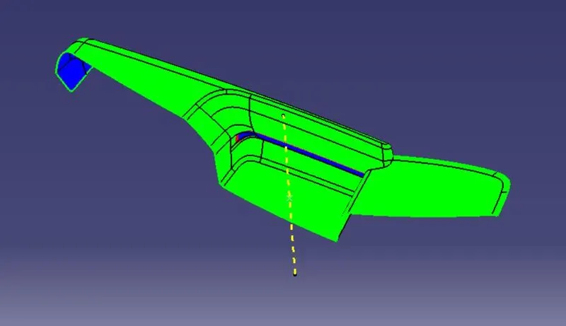
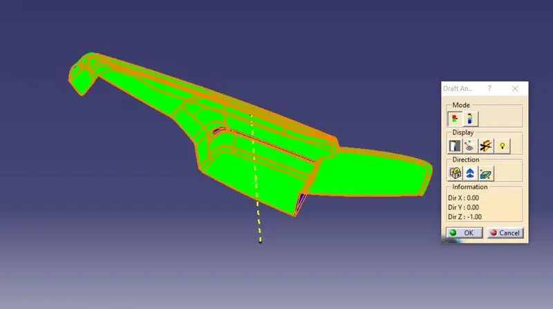
After creatig all the surfaces we can do the draft analysis for that. In plastic design, the draft analysis or angle that is considered in the OEMs is 3 degree.
A_Surface:
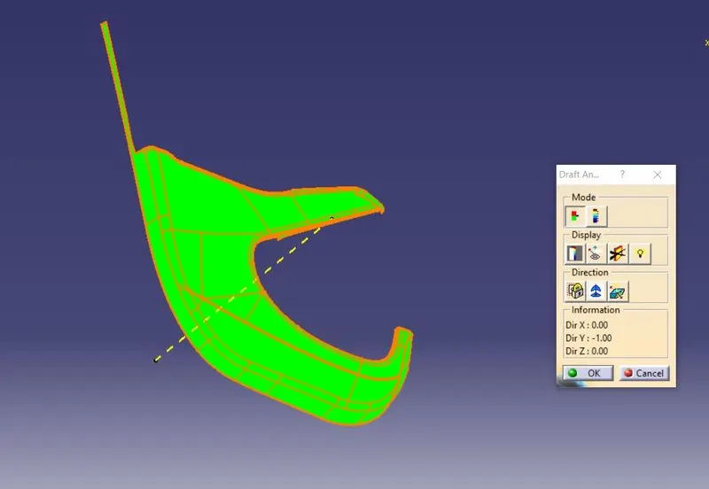
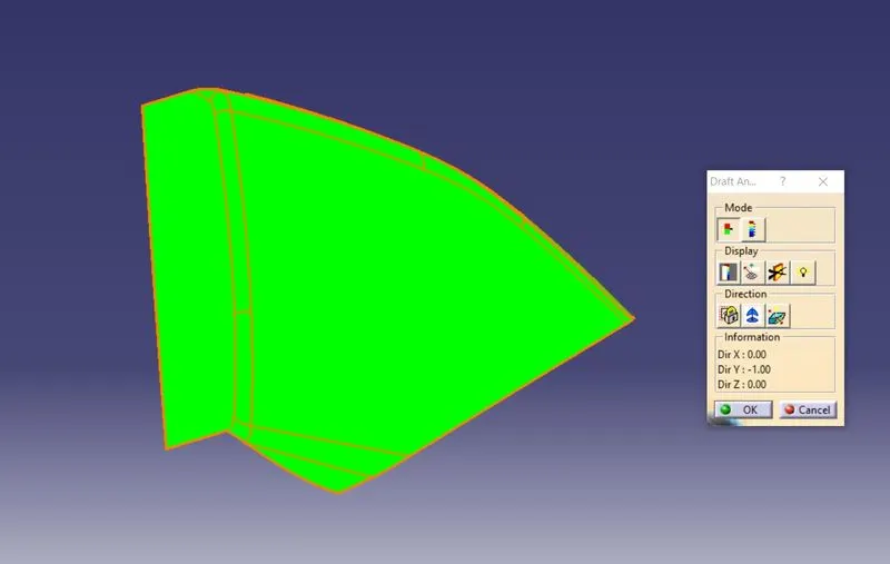
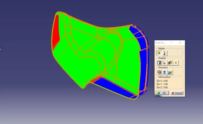
First we'll do the analysis for Class_A_surface. First we want to unhide class_A_Surface. Then go to Insert-> Analysis-> Feature Draft Analysis. Sometimes it'll some error for give material to this. We can make the part as material by using the material option. Then we'll do the draft analysis. For doing that we using the compass tool on the draft analysis window to place on the tooling axis and then lock it.
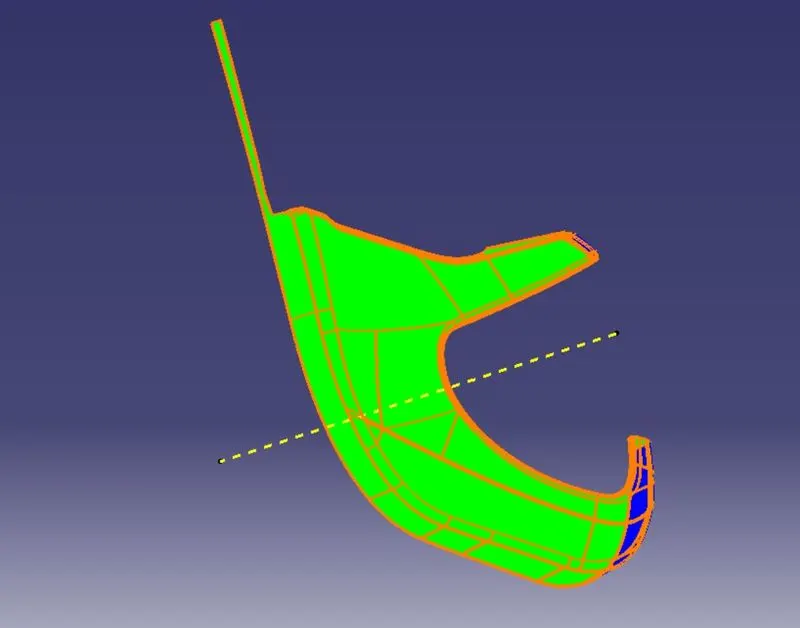
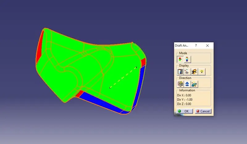
By clicking on the surface, the whole part turned into green color. If blue was visible that meant that the analysis was inversely done so just by flipping the direction, draft analysis.
The green region shows the part which is toolable or produceable by the molding machine and the draft angle is 3degree.
Blue color region states that the part can be allowed in some OEMs but still need to be improved for the other OEMs as the draft angle is more than 3 degrees.
Red color which is not there in this case states that the draft angle is less than 3 degree and cannot be produced or if produced would be faulty.
Class_B_Surface:
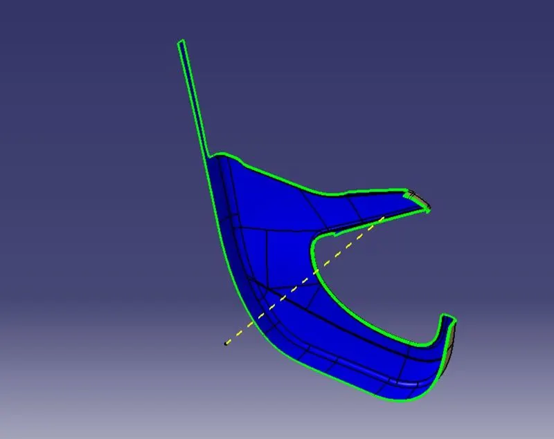
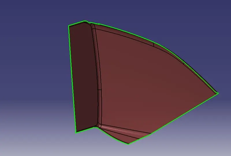
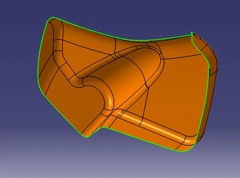
Refer the master sections to create the Offset B Surface direction. By using the master sections, we want to offset the A_Surface in the inward direction for 2.5mm. After offsetting the surface, if any errors are in it, we want to improve that B_surface for the fully closed surface.
Class_C_Surface:
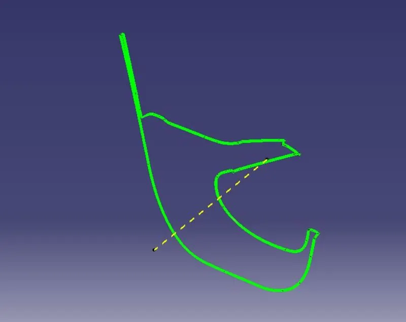
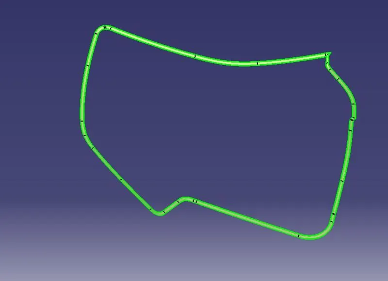
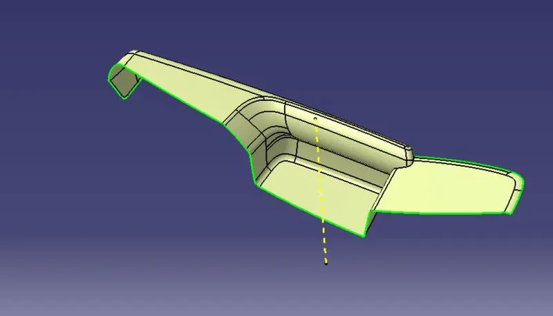
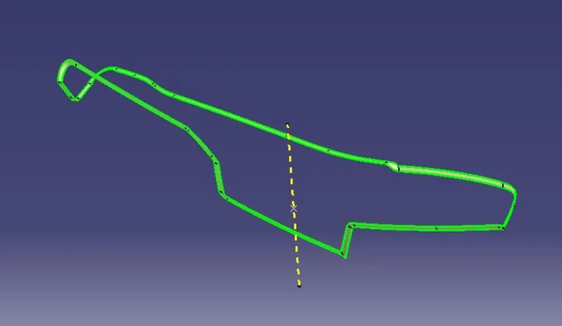
For creating the C_Surface I'm using the boundary of the A_Surface. Using the boundary of A_Surface we'll use the sweep tool to give extended surface creation on the A_Surface. If it's not working, we can use the multiple extract to create the required boundaries on it. By using these boundaries, we can use the Sweep, Multiple surface tools to create the C_Surface.
Final joined A&C:
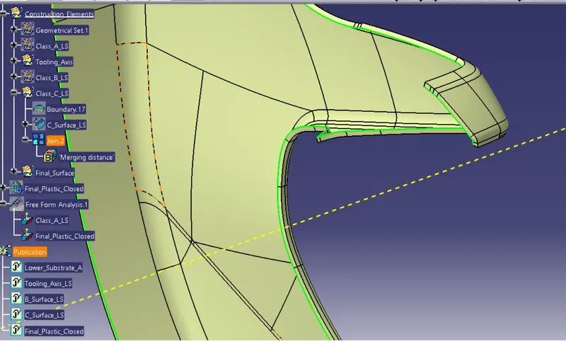
Final_Closed_Part:
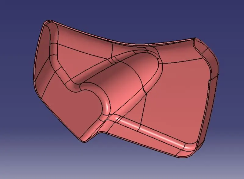
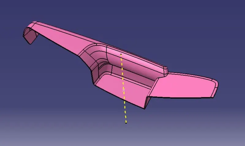
After trimming the Joined A&C with the B_Surface we'll get the Final Closed Surface of the Lower_Subtrate. Then we can use the closed surface tool in the Part Workbench, make it as the solid part.
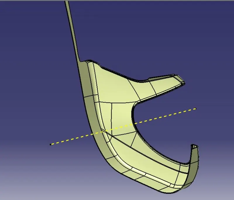
Closed_Solid_Part:
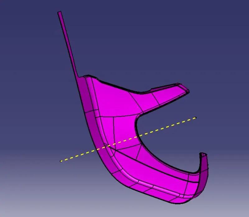
Draft Analysis For Final_Part:
OUTER_MAP_POCKET:
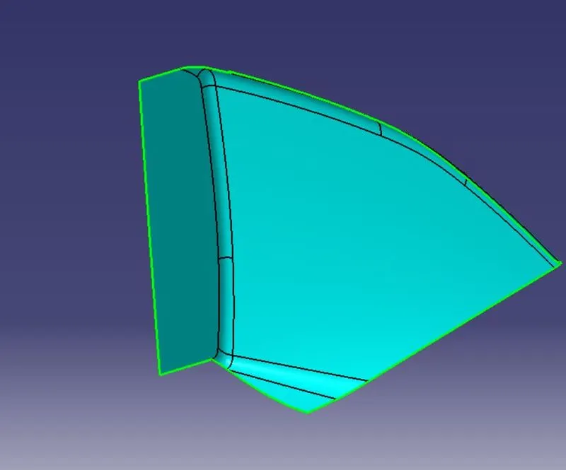
Class_A_Surface:
Tooling_Axis:
Draft_Analysis-Class_A:
Class_B_Surface:
Class_C_Surface:
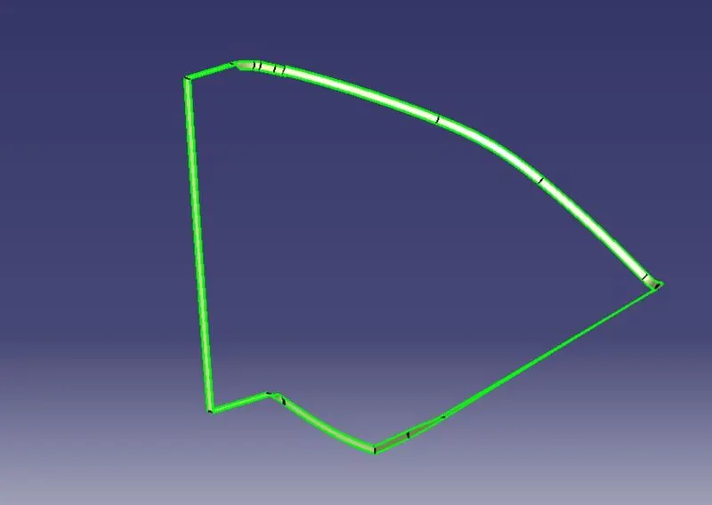
Final_Closed_Part:
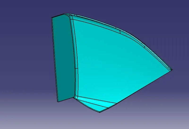
Draft_analysis-Final_Closed_Part-OMP:
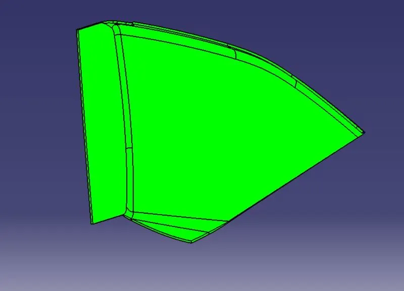
INNER_MAP_POCKET:
Class_A_Surface:
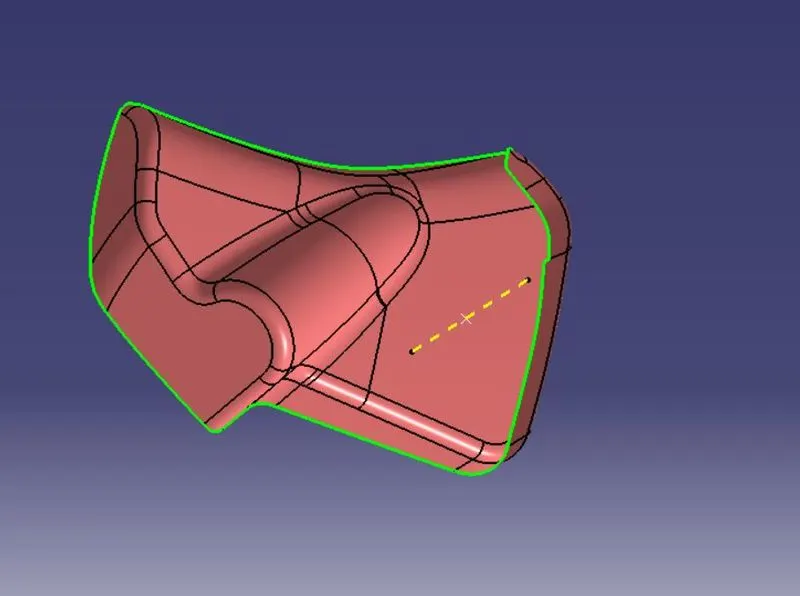
Tooling_Axis:
Draft_Anysis-Class_A:
Class_B_Surface:
Class_C_Surface:
Final_Closed_Solid_Part:
Draft_Analysis-Final_Solid_Part:
DOOR_ARM_REST:
Class_A_Surface:
Tooling_Axis:
Draft_Analysis-Class_A:
Class_B_Surface:
Class_C_Surface:
Final_Closed_Solid_Part:
Draft_Analysis-Final_Solid_Part:
In door trim panel we are going to create heat stakes, dog house, Flanges and ribs
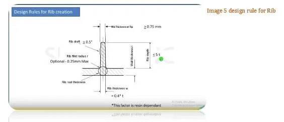
Ribs: Ribs provide a means to economical stiffness and strength in molded parts without increasing overall thickness. They also facilitate locating and arresting components of an assembly, provide alignment and act as stops or guides for mechanism
Heat stakes: Heat stakes are used to join components of similar or dissimilar material.
Thermal staking is an assembly method that uses the controlled melting and reforming of a plastic or metal component of an assembly in place. The plastic stud protrudes through the hole in the component to be locked in place.
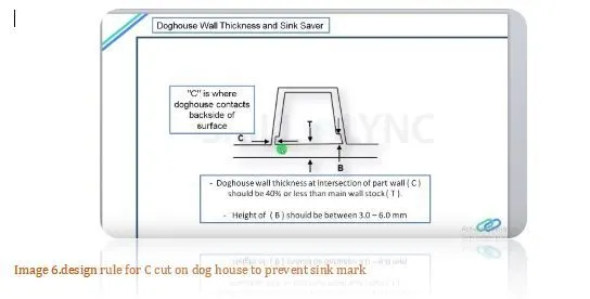
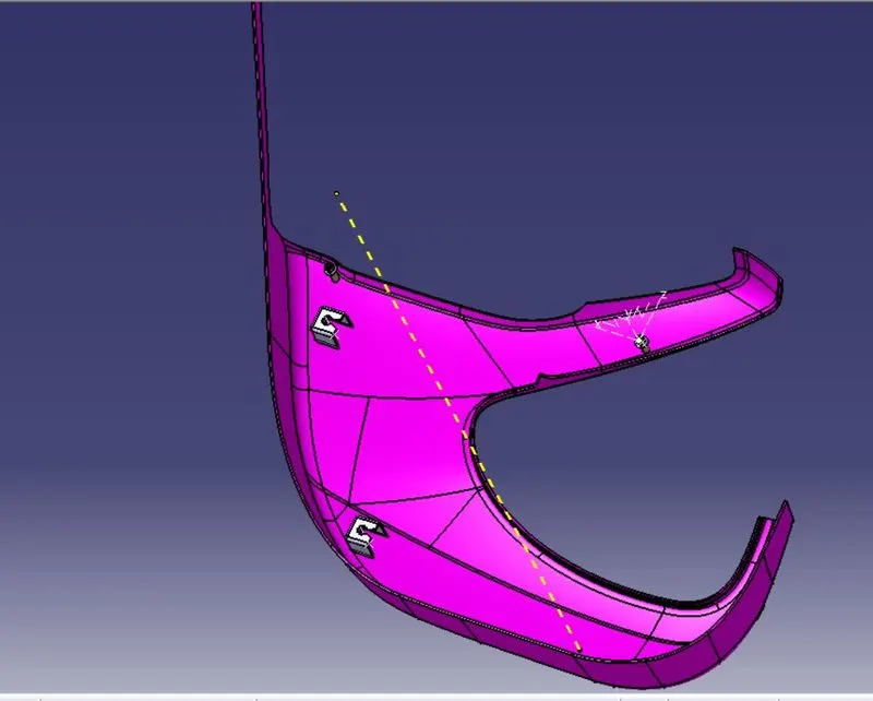
Dog house: Dog house is an engineering feature used in plastic trim design which is used as a supporting feature. Other features like locator are mounted on them to increase strength. They prevent breakage of the component during ejection.Ribs are given for dog house. Push clip is mounted on the dog house .
Dog_House_in_Lower_Substrate:
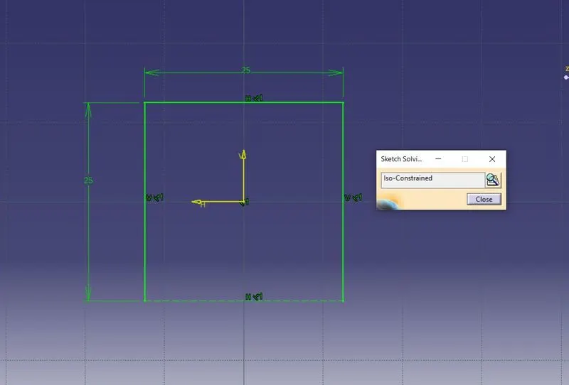
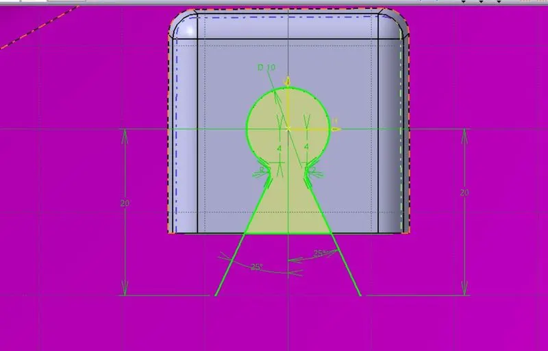
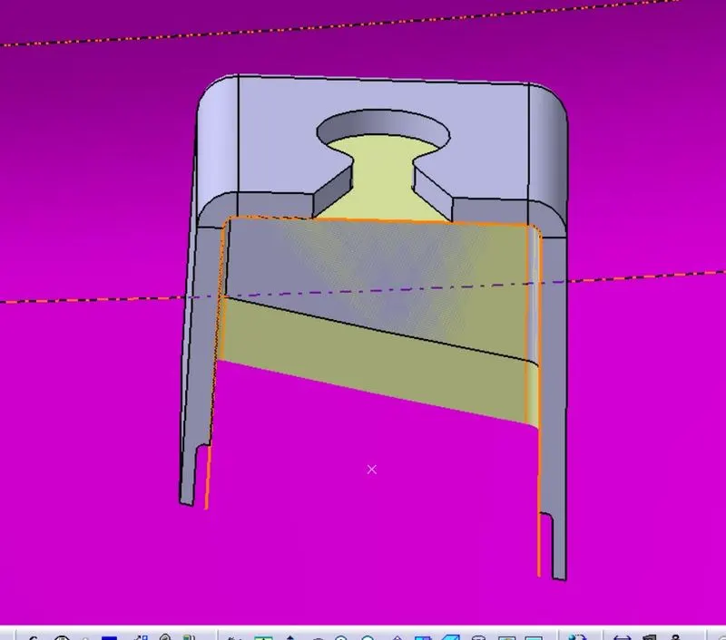
Then by using the bottom surface to offset to the required distance, we can make the dog house.
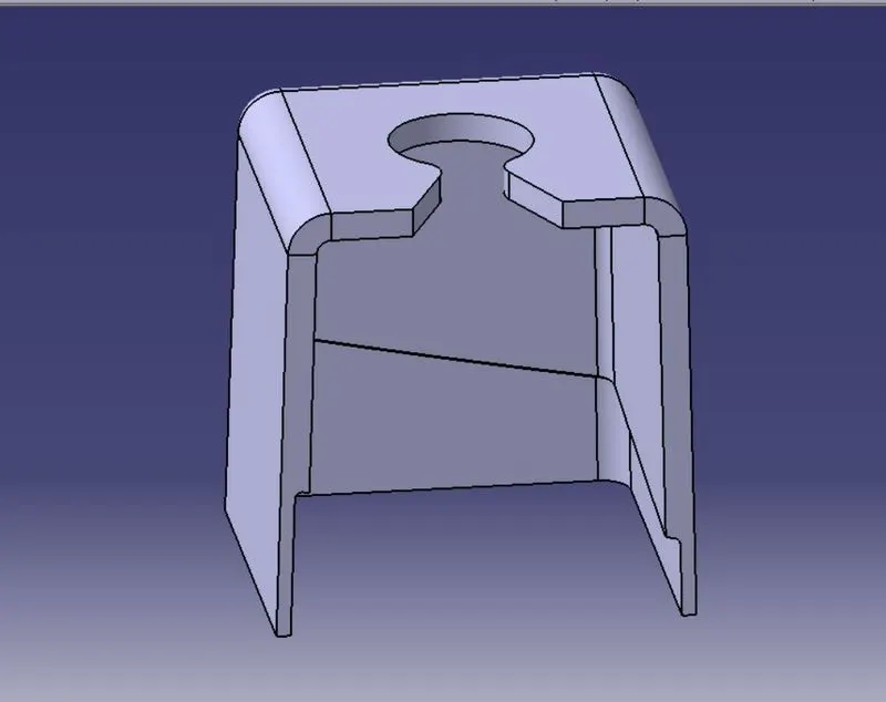
Heat_Stakes:
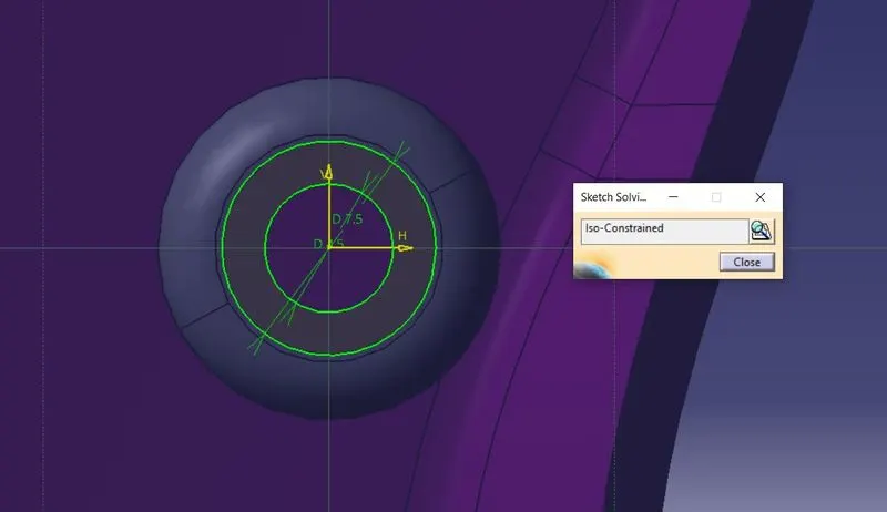
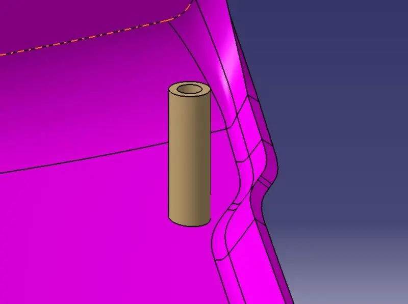
Heat stakes are created by using the master section reference, later we use the reference section curves to create the heat stakes.
Dog_House and the heat stakes in the Lower_Substrate:
Push_Pin_Clip:
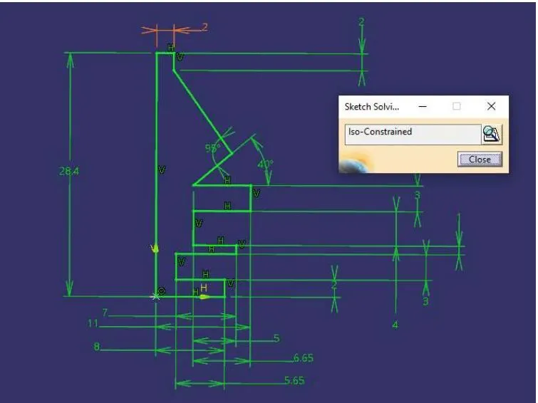
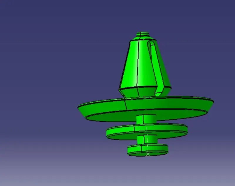
We are having the push pin from the above input download link, I'm using the same file for the assembly.
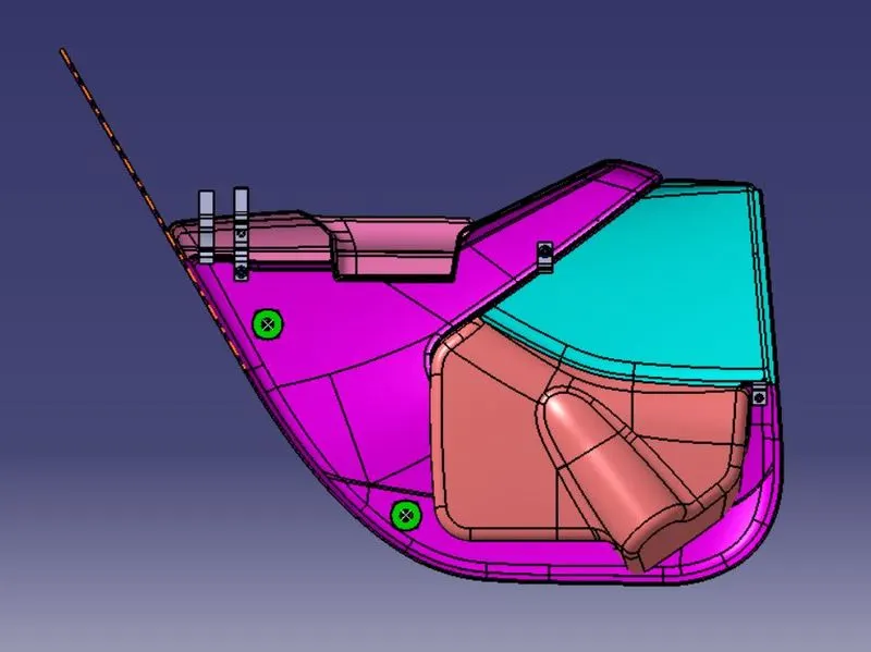
Final_Door_Trim_Panel_Assembly:
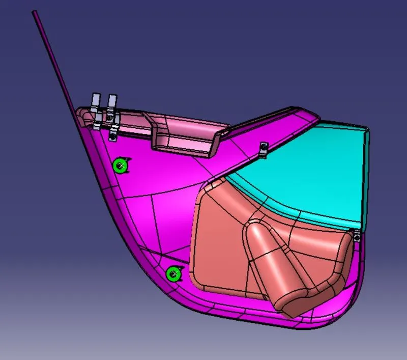
After crearting all the necessary components for the door trim panel assembly. We'll create the product file and add all the components on it, then give the constraints to it to create the door trim panel assembly.
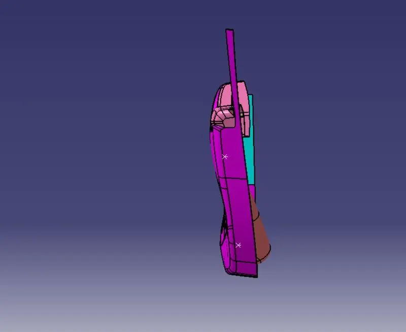
3D_View_Orientations:
Front_View:
Top_View:
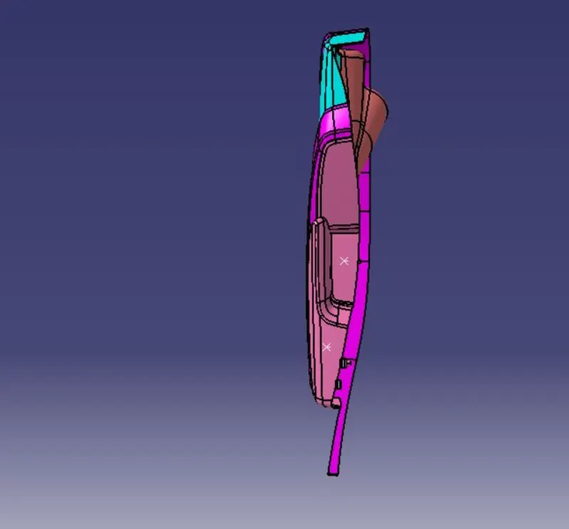
Side_View:
Isometric_View: