Week 12- Final project
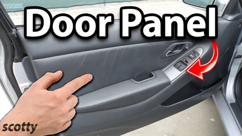
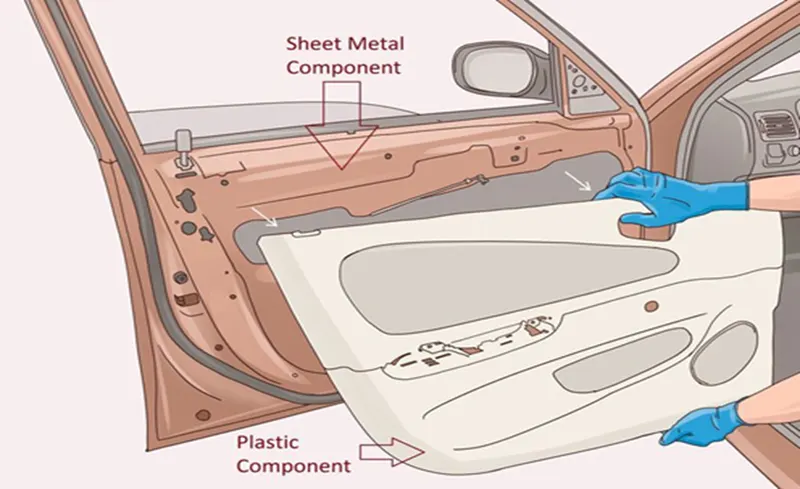
AIM: The objective of this project is to develop an innovative interior door part using inputs from Class A surface in CATIA V5. The focus will be on adhering to the design principles commonly applied in Tier 1 and OEM industries. By incorporating these guidelines, we aim to create a unique and functional door interior part.
SOFTWARE USED: CATIA V5
OBJECTIVES:
- Sketch Creation: Utilize the Positioned sketch technique to create the initial sketches. Apply Iso-Constrained settings to all sketches for accurate and controlled design.
- Organized Tree Structure: Maintain a well-organized tree structure to enhance project clarity and ease of navigation. Assign descriptive names to Geometrical sets based on their contents.
- Thickened Part Creation: Develop the door interior part by utilizing a master section as a reference. The thickened part should reflect the desired design and geometry.
- Mounting Feature Design: Incorporate mounting features in line with industry best practices and the provided master sections. Ensure the features align with the overall design for seamless integration.
- Draft Analysis & Tooling Feasibility: Conduct a comprehensive draft analysis to identify areas that may require adjustments for optimal manufacturing results. Perform Tooling analysis to validate the feasibility of the design for mass production.
- Parting Lines: Identify and create appropriate parting lines to facilitate the assembly process. Verify tooling feasibility to ensure smooth production.
Types of car plastics
The emergence of new types of plastics and the improvement of existing ones, in combination with different additives and/or materials (fibreglass) has allowed for their increased use in bodyworks.
Depending on their behaviour at different temperatures, plastics are classified into the following categories.
Thermoplastics
Most of the plastics used in vehicle bodyworks are thermoplastics. This is a type of plastic that it is hard when cold, but that softens when heated, which makes it easier to deform and weld, either by heat or with adhesives.
Their molecular thickness is generally high (composed of linear or branched, non-interlaced macromolecules). The mechanical properties of thermoplastics will vary depending on the mechanical preparation process and its level of polymerisation.
They are plastics that, because of their characteristics, are used for forming parts that must be relatively flexible, aimed at shock absorption and energies caused by small collisions: bumpers, optics, etc.
An added advantage of this type of plastic is that they allow being recycled, enabling and extending their use and life cycle. Let us look at some of the most commonly used thermoplastics:
A.B.S. (Acrylonitrile Butadiene Styrene)
- Characteristics: rigidity and dimensional stability. Provides quality surfaces and good resistance to chemical agents.
- Examples of use: spoilers, grilles, hubcaps, dashboard interiors, etc.
ABS PC (ABS Polycarbonate Alpha)
- Characteristics: greater rigidity and resistance than A.B.S. Also offers good performance in terms of traction and shock absorption.
- Examples of use: grids, spoilers, corner protectors, etc.
PA (Polyamide)
- Characteristics: is a plastic that is resistant to impact, to wear and to a wide variety of chemicals. It allows the use of different densities to make it more flexible or more rigid according to needs.
- Examples of use: grids, hubcaps, interior lining.
PC (Polycarbonates)
- Characteristics: great rigidity and hardness, and very resistant to impact. Good resistance to weathering and are easier to repair than other types of plastic (good performance for painting and welding). Capable of withstanding temperatures of up to 120°C
- Examples of use: spoilers and corner protectors, grilles, bumpers, etc.
PE (Polyethylene)
- Characteristics: one of the most widespread polymers. highly elastic on impact and easy to recover their original shape. Great performance against heat and a wide variety of chemical agents. Used also in the production of electrical components. They can begin to deform from 87°C.
- Examples of use: ducts, batteries, wheel arch liners, bumpers, etc.
PP (Polypropylene)
- Characteristics: it is one of the most widely used plastic materials in the automotive industry for different parts and components. Its performance is very similar to “Poliepileno”, although with better performance against traction, shock absorption and heat (up to 130°C). It also provides great elasticity and rigidity, and good performance against chemical agents.
- Examples of use: ducts, batteries, wheel arch liners, bumpers, etc.
PP – EPDM (Ethylene Propylene Diene Monomer)
- Characteristics: is an elastic and resistant plastic, with a great structure recovery after impact, greater than that of Polypropylene. It is resistant to most solvents and acids, and to high temperatures.
- Examples of use: bumpers, interior or exterior coatings, spoilers and flaps, etc.
PVC (Polyvinyl Chloride)
- Characteristics: in combination with different types of additives, it offers a wide variety of results, such as high-flexibility structures and other rigid ones. They are resistant to moisture, acids and solvents and to wear and tear, but not to high temperatures. Easy application of colour on its surface.
- Examples of use: electrical cables, bus floors, etc.
Thermosets
They are composed of chains of linear or branched molecules joined together to form a network that provides hardness and rigidity.
They are called like this because do not get deformed when subjected to heat, mechanical pressure or certain chemicals, always maintaining their original structure.
Unlike thermoplastics, an excessive application of heat will not cause it to deform but will result in decomposition or charring of the heated area, without altering its shape.
Therefore, they cannot be welded, but they can be repaired with other techniques, such as adhesives or resins.
Its features include high mechanical resistance and rigidity. They are mainly used on parts that will not be subjected to bending or that can withstand high temperatures, such as crankcase covers or radiator supports.
The most commonly used thermosets in the automotive industry are unsaturated polyester resins such as epoxy resins (EP) and polyurethanes (PU, usually reinforced with mineral or synthetic fillers to increase the mechanical properties of these plastics).
GU-P / BMC-SMC-MMC (Glass Reinforced Polyester Resins)
- Characteristics: these are plastics that stand out above all for their lightness and rigidity, while offering good mechanical performance.
- Examples of use: gates, hoods, grids, isotherms, channelling, etc.
EP (Epoxy Resin)
- Characteristics: they offer variety in terms of stiffness and elasticity performance. They can be reinforced with loads and fibres. Good adhesion on other plastics, with the exception of olefinics (PE, PP). Resistant to corrosion and chemical agents.
- Examples of use: modification of bodywork parts such as skirts, bumpers, heel cups, spoilers, etc.
GFRP (Glass Fibre Reinforced Plastics)
- Characteristics: they are very hard and resistant. They incorporate glass fibres and thermosetting resins (polyesters, epoxies, etc.). They cannot be welded, but they can be repaired.
- Examples of use: bumpers, dashboards, etc.
Elastomers
The main characteristic of elastomers is that they are highly flexible and elastic. When faced with external pressure, they tend to deform, recovering their original shape when the pressure ceases.
Once broken, they are more difficult to repair. These plastics are repaired by using adhesives, as they cannot be welded since they degrade when excessive heat is applied.
Most elastomers are composed of versions of rubber, such as thermoplastic polyurethane (PU or PUR if reinforced), ethylene-propylene-diene (EPDM) or styrene-butadiene (SBR).
In the automotive industry, elastomers are mainly used for parts such as spoilers, gaskets or rubber for windows.
Methods for identifying the type of plastic in the bodywork
Due to the rapid evolution of these components in the sector, it is essential that professionals know in depth the different types of plastic that make up a car, their behaviour, and the ideal repair processes to obtain an optimal result and reproduction.
Not in vain, at present, plastic is used in vehicles around 18% in a mid-size model. This figure is expected to increase further in the future.
Knowing in depth the different types of plastic used in the automotive industry will help to optimise their repair. Let us now look at some methods for correct identification
CLASS As (INPUT)
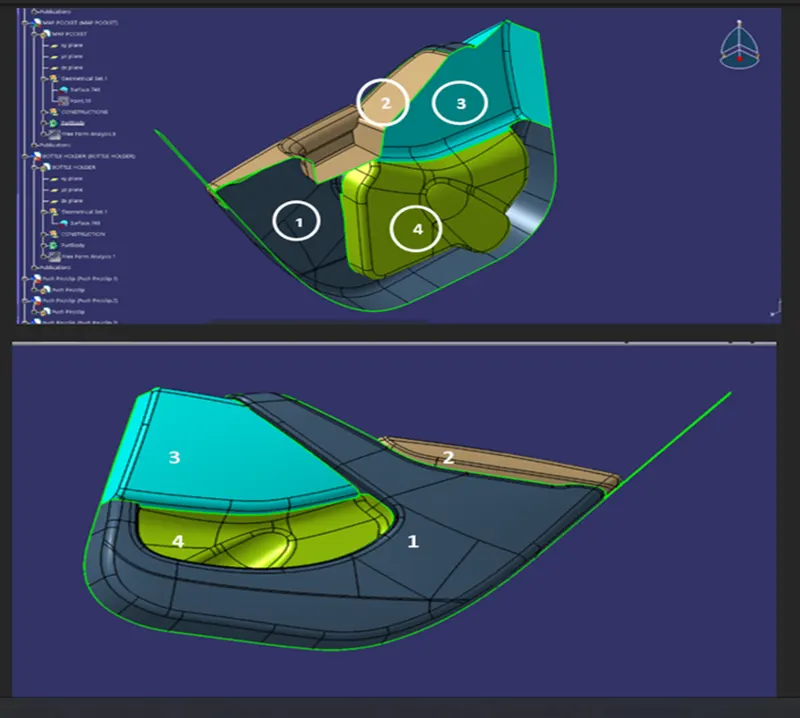
PARTS NAME :
1.Lower substrat
2.arm rest
3.map pocket
4.bottel holder
Class A surfaces refer to the highest quality surfaces used in automotive and industrial design. These surfaces are essential for achieving a visually appealing and flawless appearance of a product. Class A surfaces must meet strict criteria, including smoothness, continuity, and lack of visible defects. They are typically used for visible and tactile parts of a product, such as exterior body panels, interior trim components, and consumer electronics.
Prior to work on class A
- Import Class A Surfaces:
- Open your CATIA V5 software and create a new part design file.
- Use the appropriate import feature to bring in the Class A surface data into the CATIA environment. Ensure that the imported surfaces are of high quality and meet the required standards.
- Prepare the Surfaces:
- Examine the imported Class A surfaces for any defects or gaps that might hinder the creation of a solid body.
Visual Inspection:
Conduct a visual inspection of the lower substrate to identify potential areas where tooling access might be required. Look for complex curves, tight corners, or areas where the part might have undercuts.
1 .Main tooling axis refers to the axis or direction along which a tool or Mold moves during a machining or moulding process. The tooling axis is a critical consideration in designing molds and fixtures for various manufacturing processes, as it determines the tool's path and affects the final outcome of the production.
2.sidecore axis, also known as a sliding axis or side action, refers to an additional axis of movement used in moulds or dies to create undercuts or complex features in the molded or stamped part. Sidecore mechanisms are essential when designing molds for injection molding, die casting, or other similar processes where the molded part has features that cannot be directly formed by a straight pull of the mold.It enables specific portions of the mold to move laterally or perpendicular to the main tooling axis to release undercuts.
- Lifters or Lifter Axis:
- Lifters are mechanical components that move perpendicular to the mold's main parting line. They help lift specific sections of the mold to release features like bosses or pins in the molded part.
LOWER SUBSTRATE;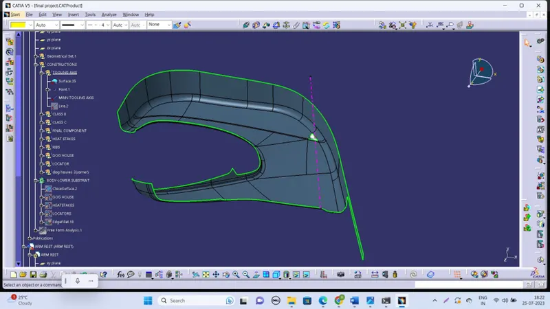
Hear the best possible tooling axis is in Y direction. So the tooling Was created By taking a point on the surface and taking a line in the direction of Y. (That is point AND direction option.)
And for this part Side core axis is not needed.
Arm rest;
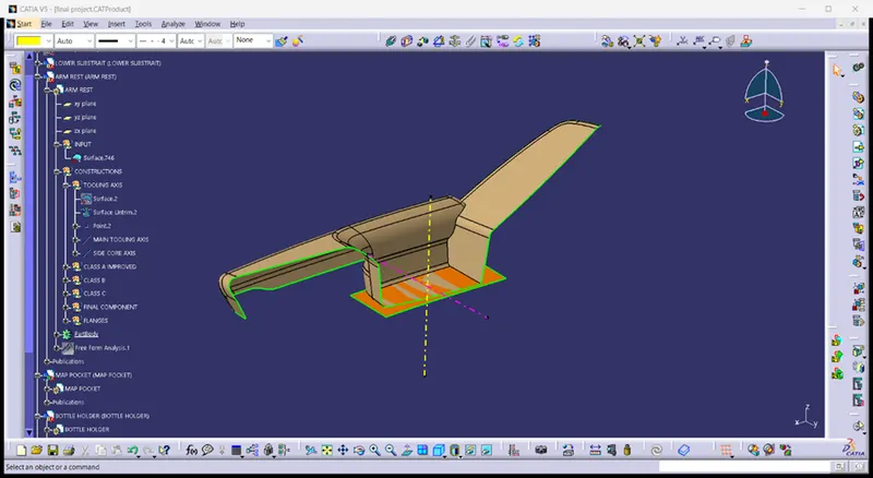
Hear the best possible tooling axis is in Y direction. So the tooling Was created By taking a point on the surface and taking a line in the direction of Y. (That is point AND direction option.)
Here, the Amrest has undercut. And also. It cannot be created in one mold. Due to its complexity. So for the undercut, we have side coring axis also.
Map pocket;
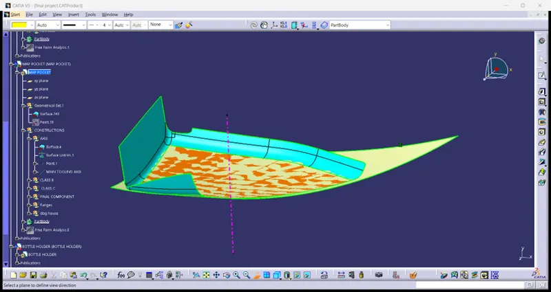
Hear the best possible tooling axis is in Y direction. So the tooling Was created By taking a point on the surface and taking a line in the direction of Y. (That is point AND direction option.)
Bottle Holder;
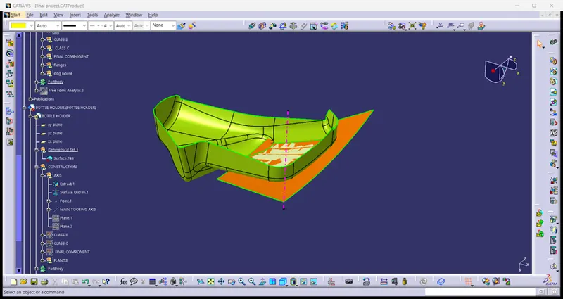
He’s the best possible tooling. Direction is Y axis So I have created. By creating a point on The Extracted flat Surface of the Class A. and and selecting a point-direction(line) option I have created a line along the direction of Y axis because this could be. The possibly the correct one.And for this part Sidecoraxis is not needed.
Draft analysis in CATIA is a powerful tool used to evaluate the manufacturability of a designed part for molding processes. By analyzing the draft angles of the part's surfaces, it helps to determine whether the component can be easily ejected from the mold without any interference or undercuts. The draft analysis provides visual feedback using color mapping to identify regions that do not meet the required draft angle criteria.
This analysis is crucial during the early stages of product development, as it allows designers and engineers to identify potential issues that could arise during the molding process. By ensuring sufficient draft angles, the risk of production problems and costly modifications to the mold can be minimized.
During the draft analysis, CATIA examines the angles between the part's surfaces and the direction of mold opening. Proper draft angles enable smooth ejection from the mold without causing any damage to the part or the mold itself. The color range displayed on the analyzed element helps users quickly visualize problematic areas that require adjustments to meet the necessary draft angle specifications.
NOTE: THE DRAFT PROVIDED IS 3 DEGREES FOR BELOW ANALASYS.
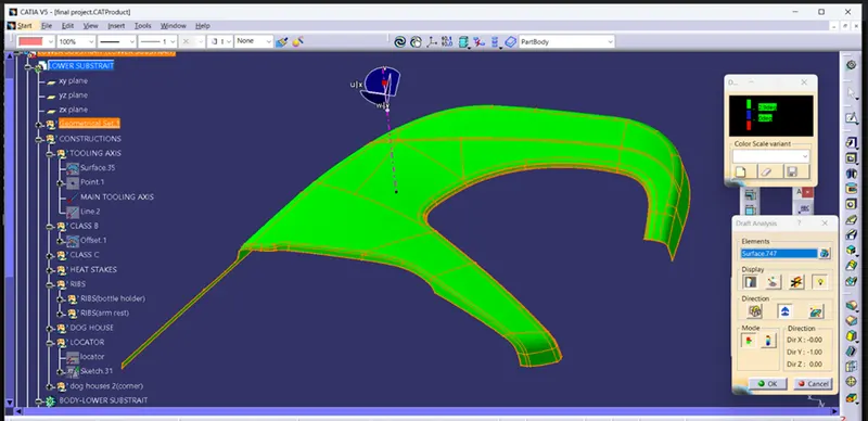
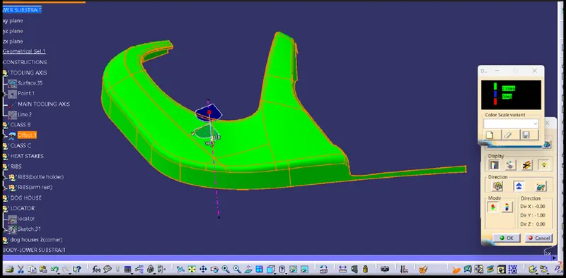
Amrest.;
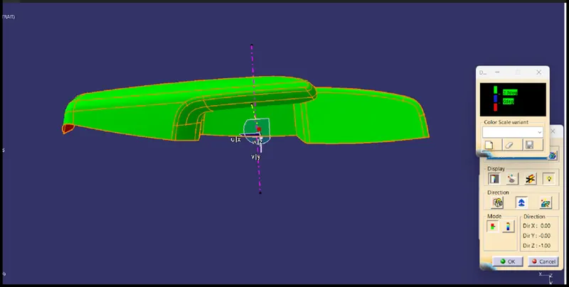
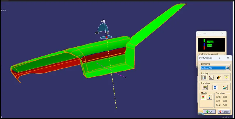
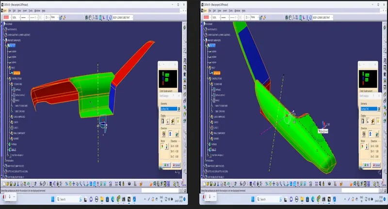
1.Due to the Complexity of the shape the draft is not cleared in one main tooling axis so the side axis side core axis is needed because of undercut and due to its curvy shape on backside it cannot be created in one mould
- From the figure it can be seen that the undercut is cleared in side core axis.
Map pocket::
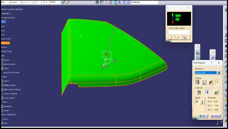
1.the map Pocket is clearing three degree draft
Bottle holder::
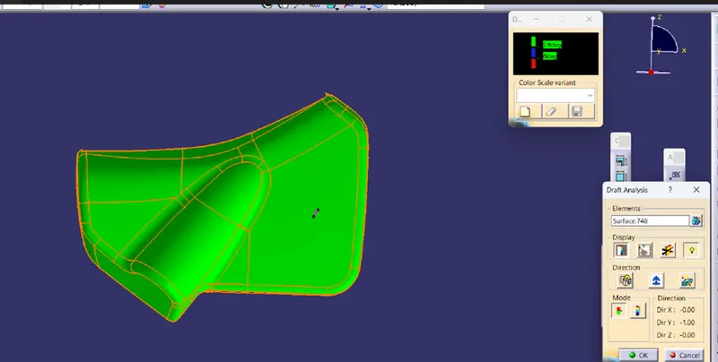
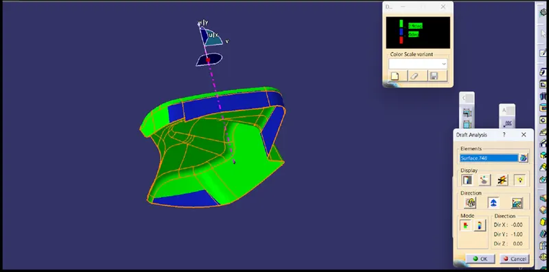
1.from the above we can see that it is not clearing.soSo the respective places Are concerned with styling engineer.
Lower substrate CLASS B
While creating Class B with the help of Class A, input. Is not. Easy always. Sometimes the offseted surface of Class A. to a given thickness. Produces a produces undesirable class B with missing of some parts of surfaces. At locations of complexity. Shapes. Especially at filets.
So we have to manually use commands. Repair that area/surface
Lower substrate Class C. to create class C surface, which is between Class A and Class A. which we can say as the thickness side. Which broken which has a draft broken down is created mostly by sweep command. Here we used with reference option
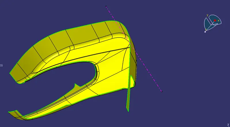
Armrest
To create Class B from Class A We used same procedure as above mentioned
Here we used draught with angle of three degrees by using sweep
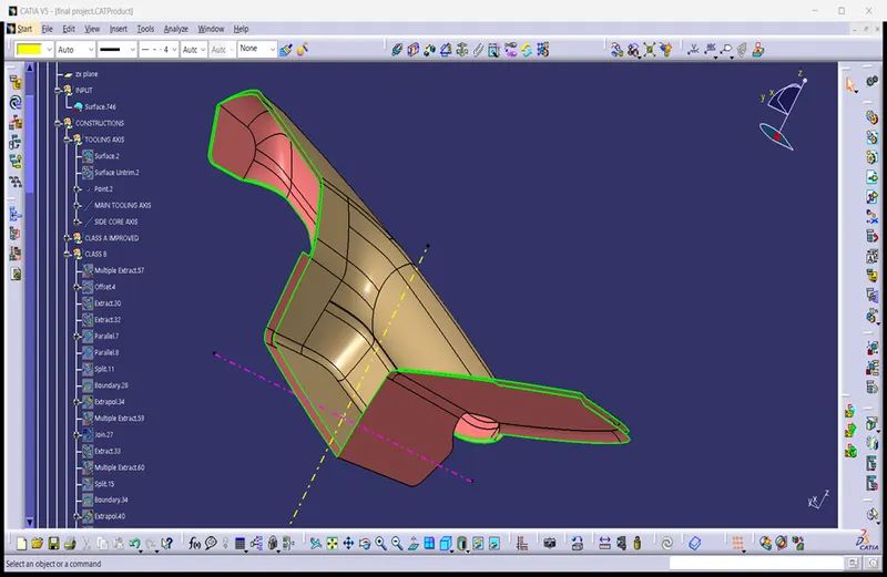
MAP POCKET,CLASS B:
The same step is followed as above to create the class B surface
GREEN COLOUR-CLASS A
RED COLOUR -CLASS B SURFACE
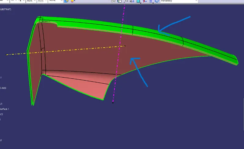
bottle holder:
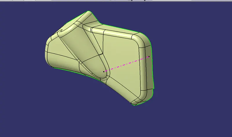
Class C’S:
LOWER SUBSTRAT
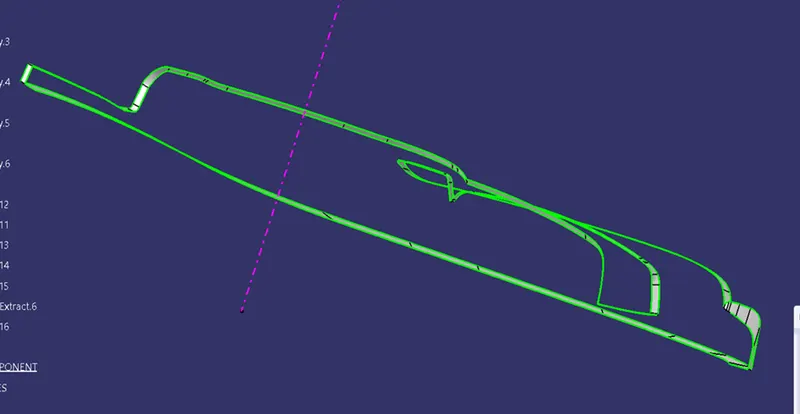
2.armrest
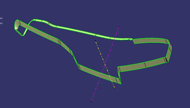
3.Map pocket
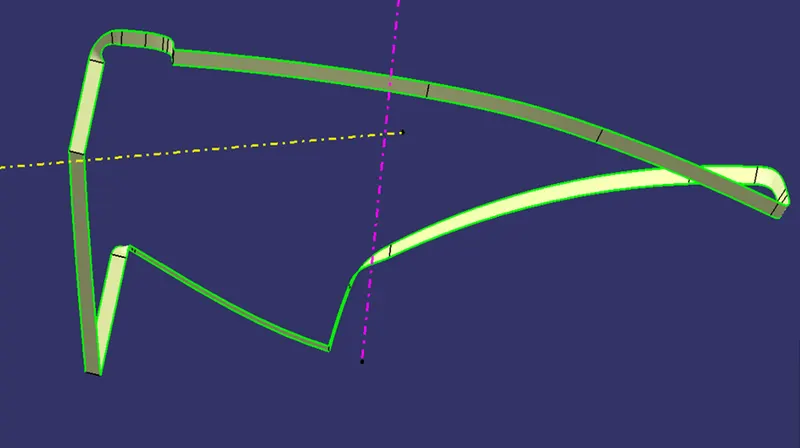
4.bottle Holder
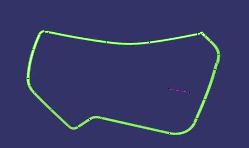
Closed bodies
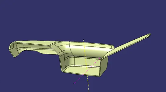
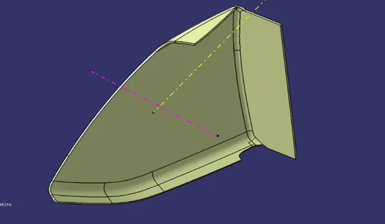
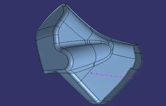
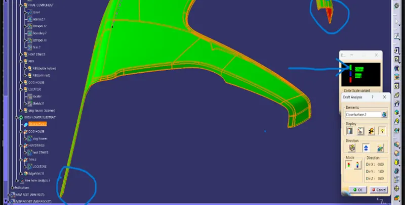
DRAFT ANLYSIS OF SOLIDS: With 3 degree draft angle
1.lower substrat
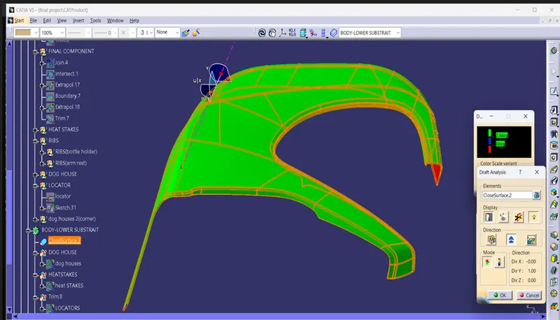
- The The below images shows that the draught is not clearing that is why it is in blue colour
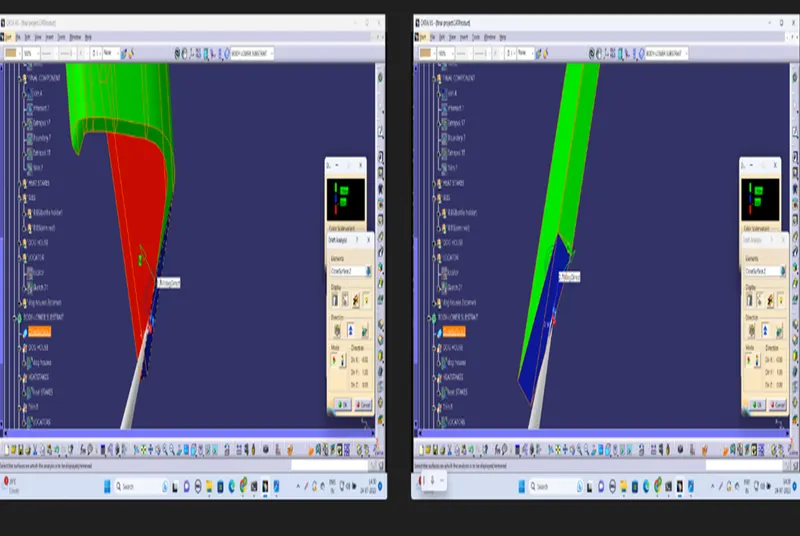
2.the draft is clearing at 2.7 degrees that we can see it from the below image
ARM REST:
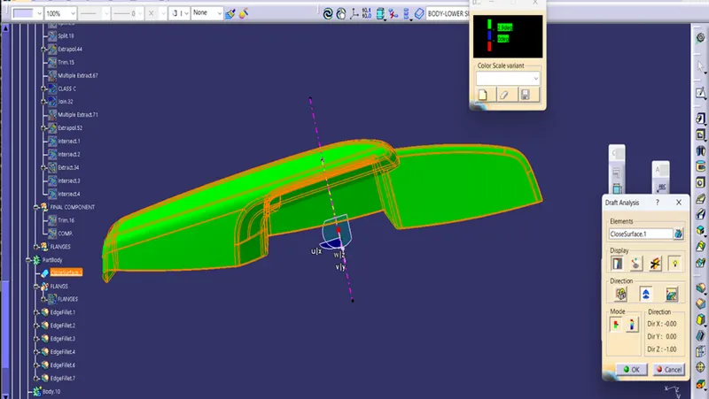
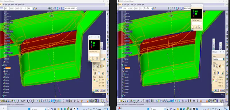
1.THE DRAFT WHIS IS NOT CLEARED ABOVE IS CLEARED BY GIVING 2.7 DIGREES AND OTHER SIDE IS CLEARED IN REVERSE DIRECTION Y SIDE CORE AXIS AND UNDERCUT AS WELL CLEARS BY SIDE CORE AXISASSHOWN BELOW
map pocket:
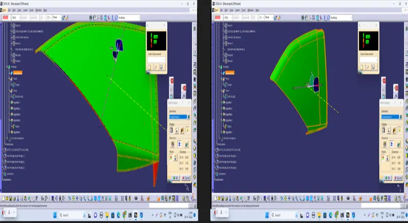
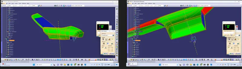
THE C SURFACE ARE NOT CLEARING FOR THE MAP POCKET .
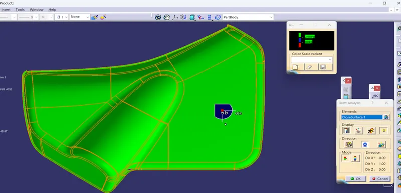
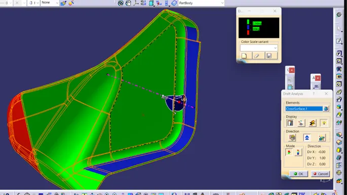
The sides shown above are not clearing the draft .
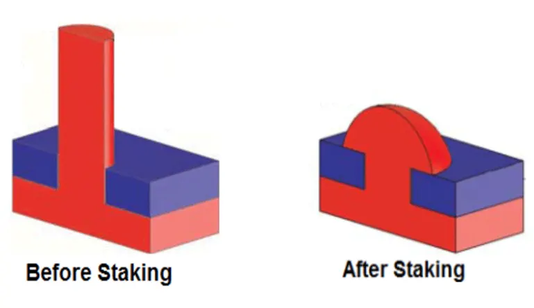
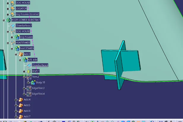
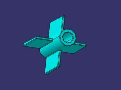
Heat stakes:
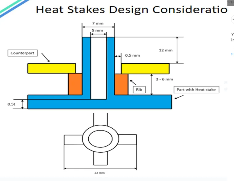
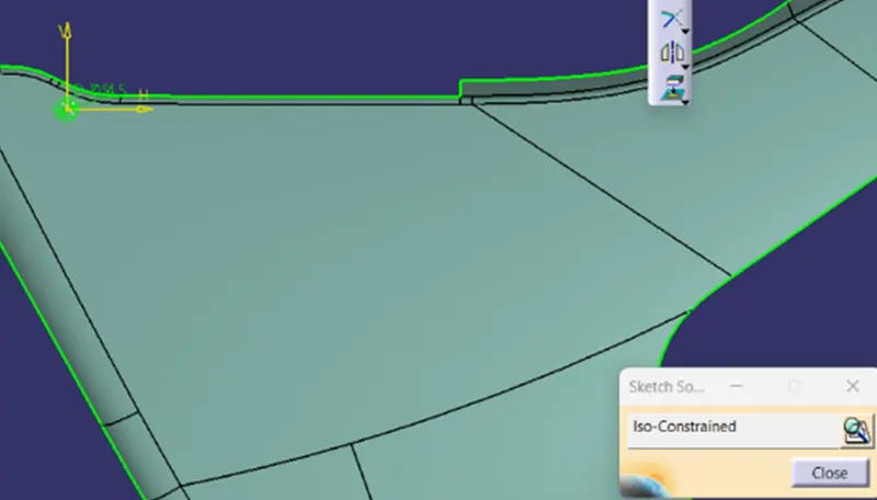
Iso constrained sketch status of heat stake :
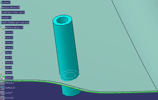
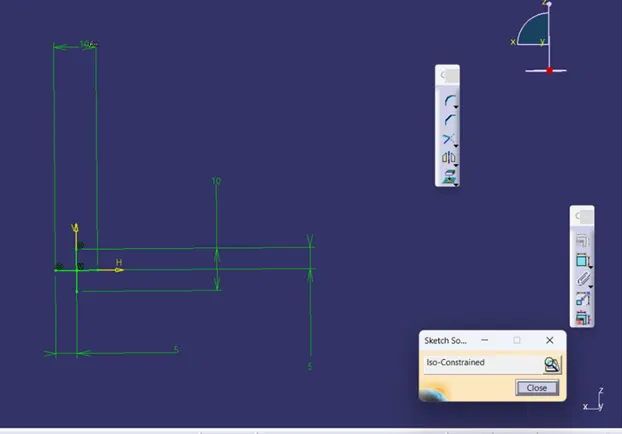
Ribs for heat steak
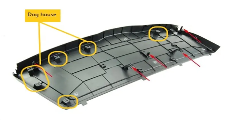
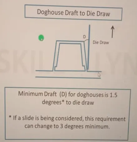
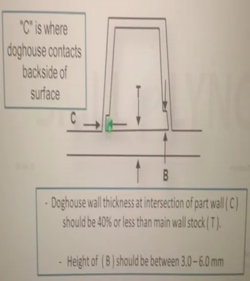
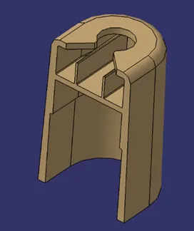
Dog house
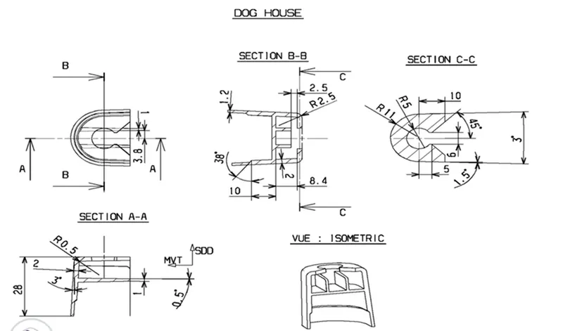
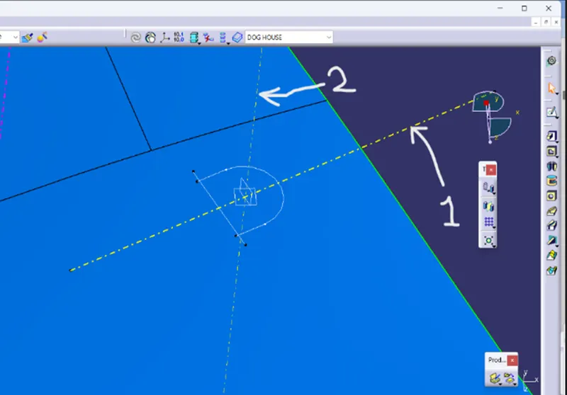
Tooling axis of dog house and sketch:
1:lifter axis
2:main tooling axis
Surface creation:
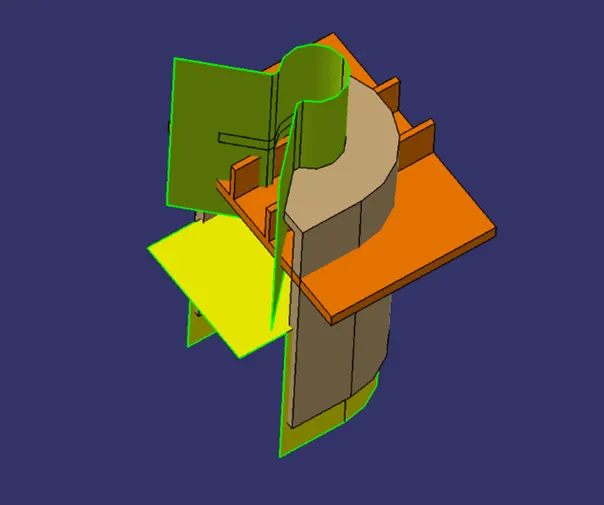
Closed surface:
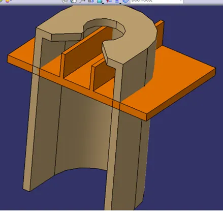
The body:
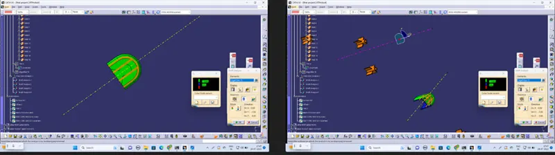
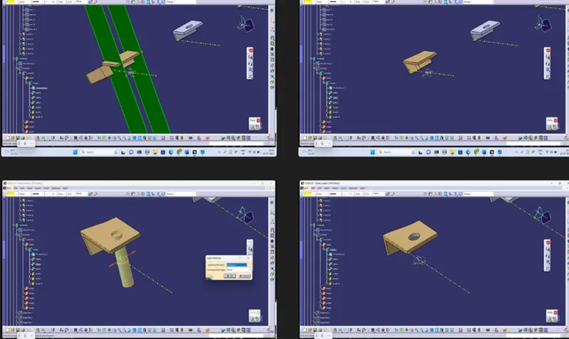
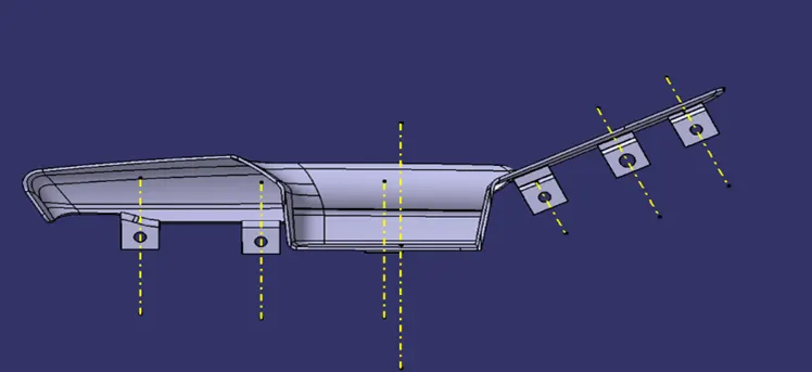
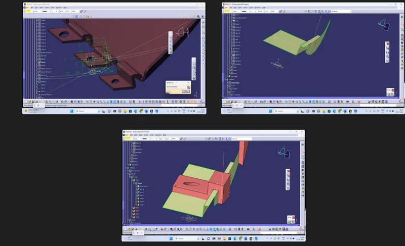
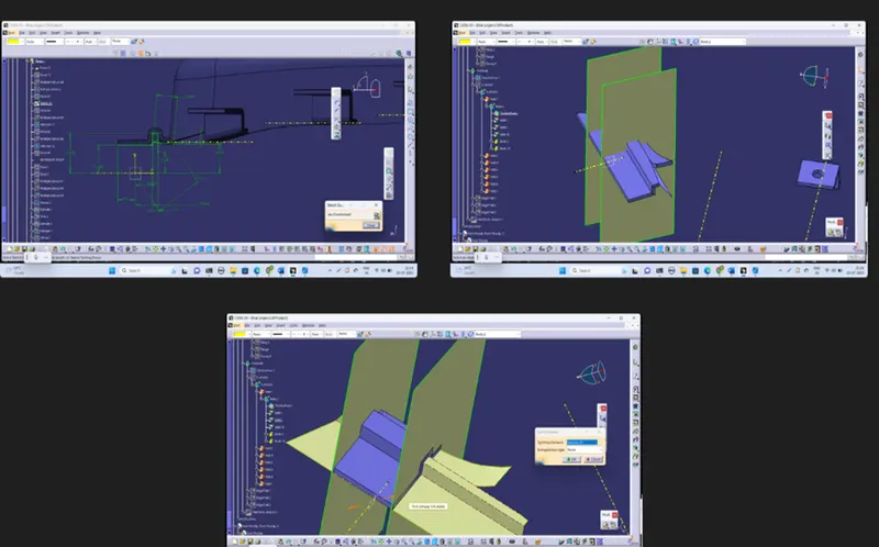
FLANG :
1.for ARM REST:
Sketch solving status of flang
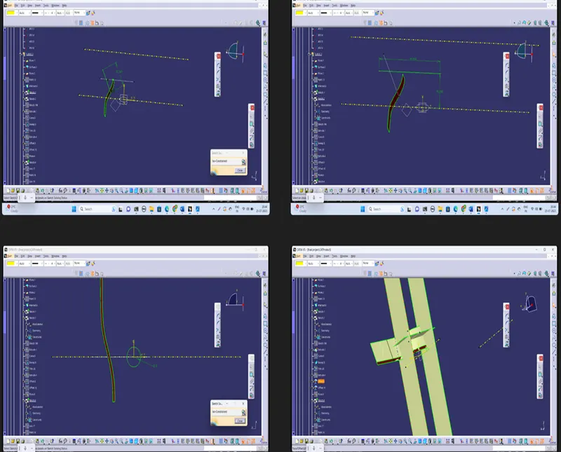
For map pocket
BOTTEL HOLDER:
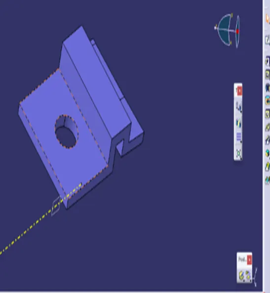
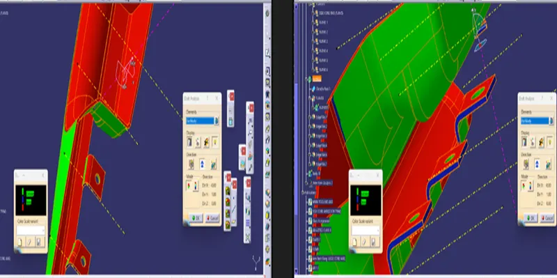
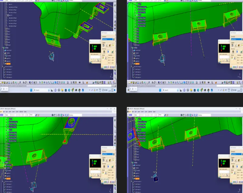
DRAFT ANLYSIS OF ENGINEERING FEATIRES LIKE FLANGES,DOG HOUSE,HEAT STAKES,LOCATORS
Locators: WITH MAIN TOOLING OF LOWER SUBSTRAT with 1.5 degree draft
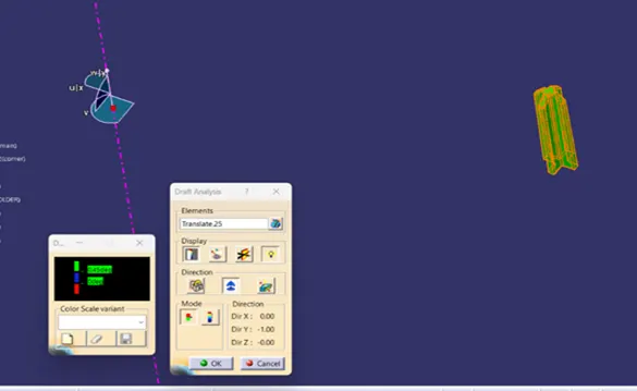
DOG HOUSE: WITH lifter axis with 0.5 degree draft (below image)
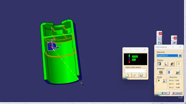
WITH maintooling axis of LOWER SUBSTRAT with 1.5 degree draft (below image)
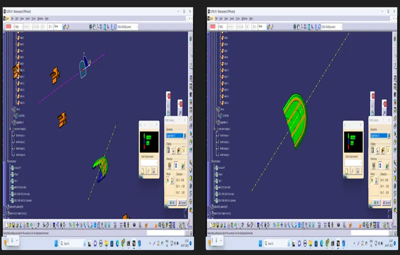
Flanges perfectly clearing draft of 0.5 degrees.
Here every flange has a side core axis of its own if not provided it means it can be cleared with the side core axis of the main part upon which it is featured and main tooling axis of the respective component can clear the features. The images are provided below clearing main tooling axis and with side core axis correctly with a draft angle of 0.5.
1.The below images shows the draft analysis of flanges for armrest
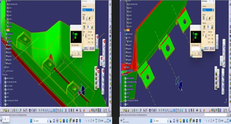 The below image shows the draft analysis of Flanges of bottle holder in both directions clearing the draft of 0.5 degree
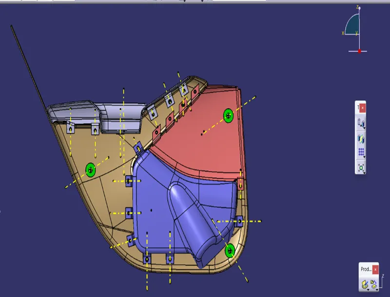
The below image shows all the tooling directions of the engineering features and main parts
Both main tooling axis and lifter axis or side core axis
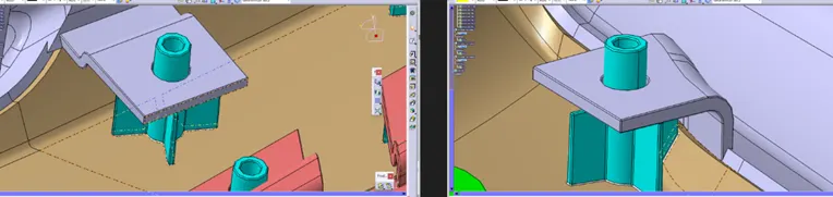
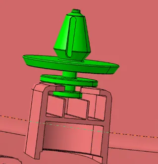
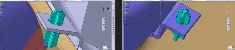
Screenshots of engineering features
Screenshots of engineering features
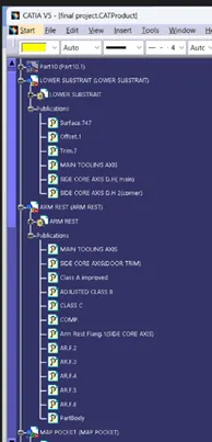
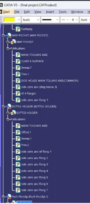
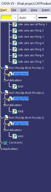
Screenshots of published elements
Different views of the final assembly
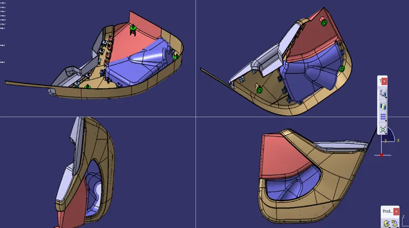
THE PROJECT IS DONE ACOORDIND TO THE GIVEN CRITERIA