Week 10 - Challenge 1- Attachment Feature Creation (Ribs & Screw Boss)
AIM: TO Create the Screw boss for the Drill Handle considering the design rules mentioned.
General Guidelines for Bosses:
- Draft - 0.5 degrees on the walls of boss
- Thickness - Typically 40%* of the nominal wall at the base.
- Height to Diameter Ratio - 3:1
- Radii - 0.25mm maximum radii.
REFERENCE PICTURES
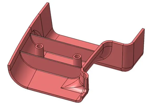
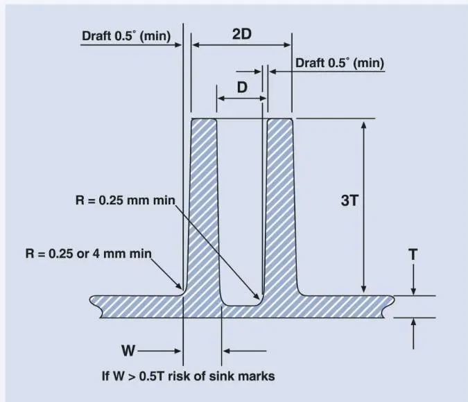
- Reference
- Refer to the below-given image to understand the position of the Screw Boss and Ribs
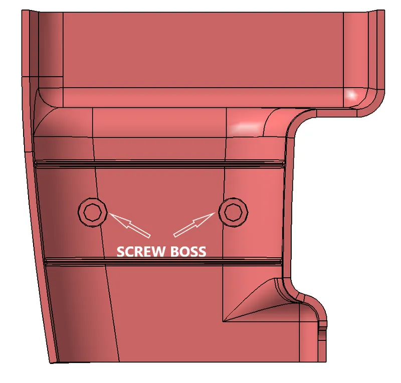
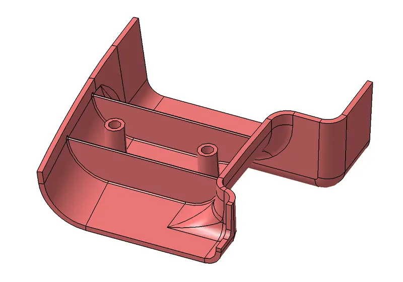
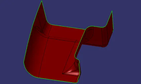
CLASS A(INPUT)
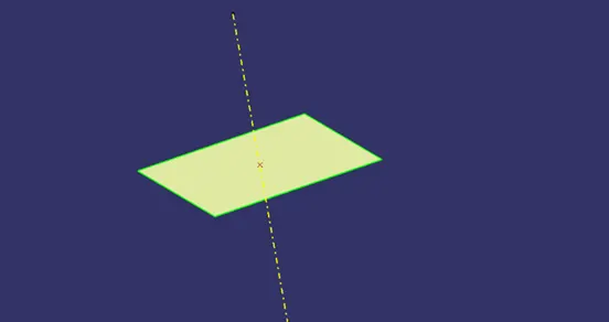
CREATION OF TOOLING AXIS.
1.EXTRACT THE FLATE FACE AND BY USING POINT DIECTION CREATE THE LINE BECAZE THIS COULD BE THE CORRECT DIRECTION.
-
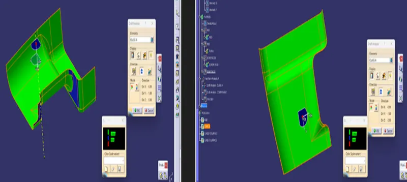
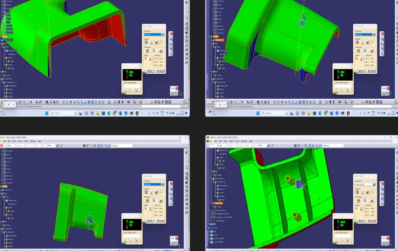
Draft analysis of Class A with three degree draft it has some unclear faces so that could be corrected by stylish engineer.
 Creation of class B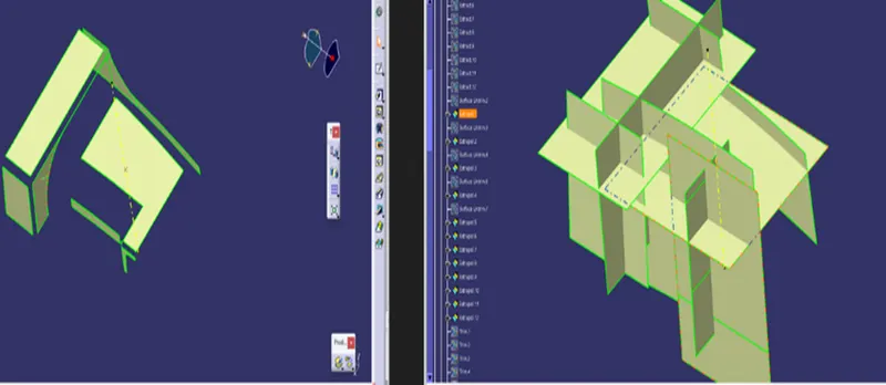
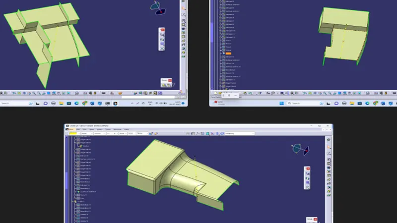
Creation of Class C and final component TRIM
-
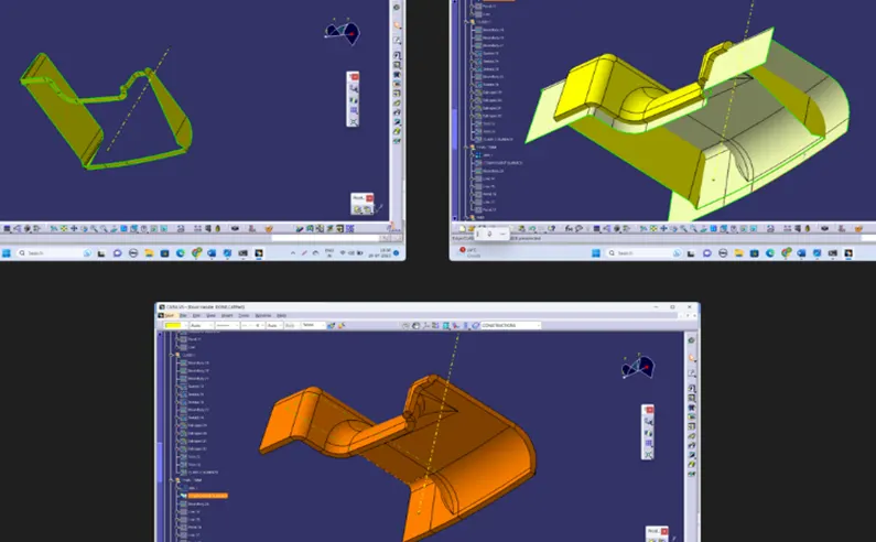
-
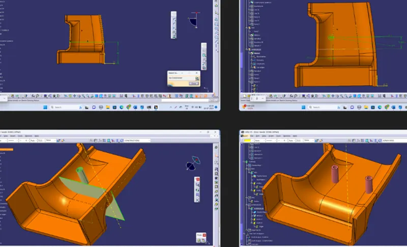
Sketches of ribs and screw bo.es with sketch-solving status AND surfaces
-
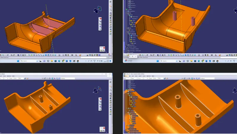
Creation of closed body by surface
-
NOTE : And the height of the screw bosses are not according to the design rule because the height is very less than the ribs so by the given reference diagram or image we increase the screwbosss height to approximate height as from the reference image.
There are some faces which are not cleared for final solid with three degree draft.But Engineering features like ribs and screw boss Clear to the draft with 0.5 degree.
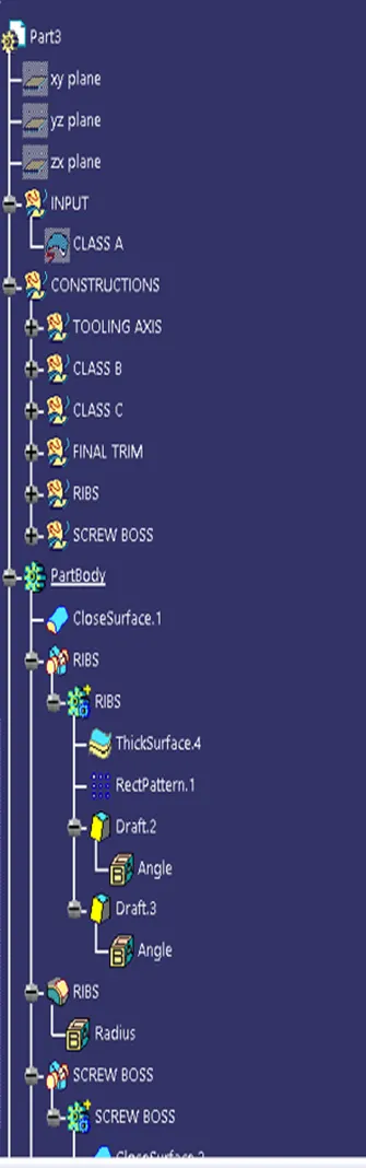
Tree structure And published elements

-
NOTE : And the height of the screw bosses are not according to the design rule because the height is very less than the ribs so by the given reference diagram or image we increase the screwbosss height to approximate height as from the reference image.