Week 9 - Challenge 2 - Switch Bezel Design
BELOW IS the explanation given on the way of creating the tooling axis, particularly the Bisecting method.
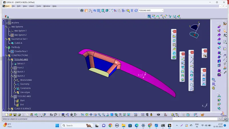
step 1, extract the surface which is taken as a reference
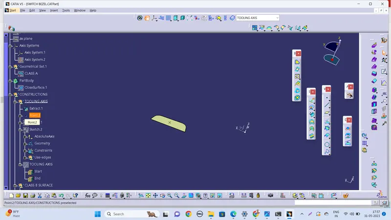
STEP 2, create the point and a axis system on the surface
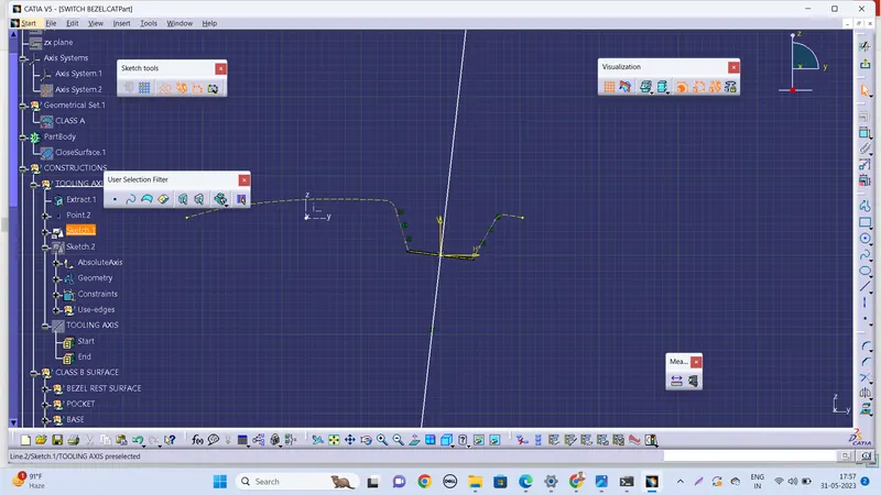
STEP 3, intersect the class A with the plane and using positioned sketch draw lineson the the draft side as in above figure and using the two slant lines on either side of the point draw bisecting lines ,and make all other lines as construction lines
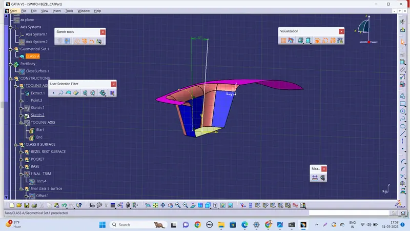
now using XZ plane intersect the CLASS A, And using sketch draw a line from the point and and taking surface a a reference take a n ange of 5 degrees and chang other lines as construction elements
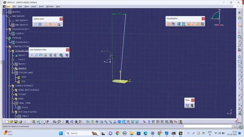
as in the above figure
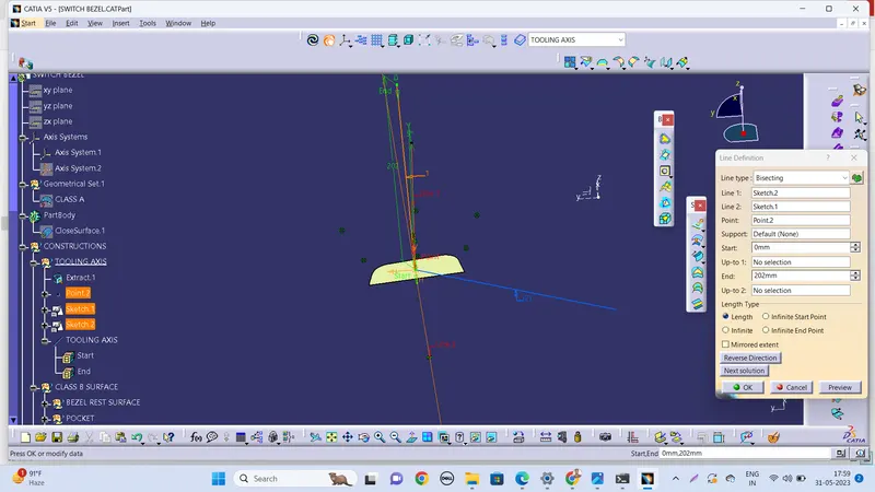
now using the lines foem above two sketches draw a bisectingline taking point as a reference
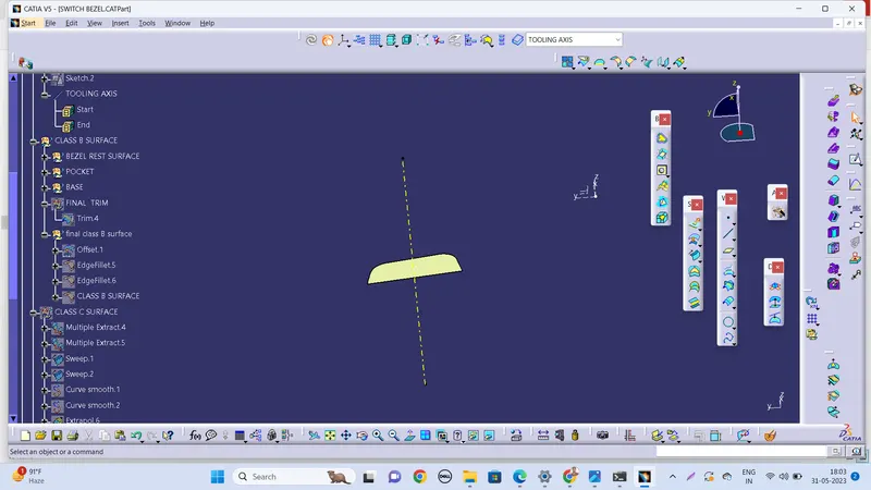
now the line which we got is a TOOLING AXIS as in above figure
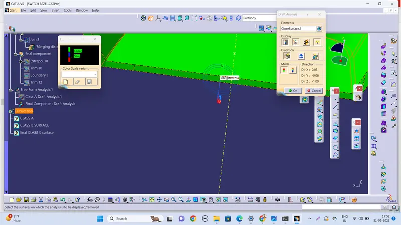
below are the Screenshots of Draft analysis report for the given Class-A surface
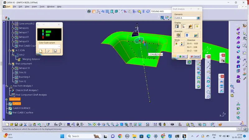
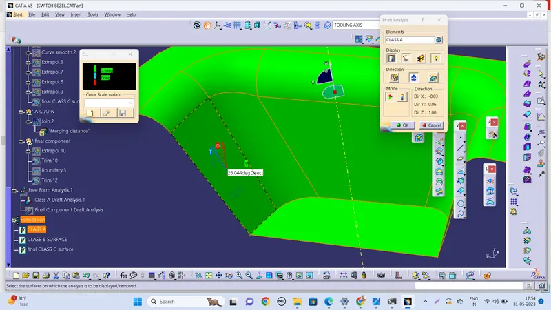
below are the Screenshots of Draft analysis report for THE FINAL COMPONENT surface
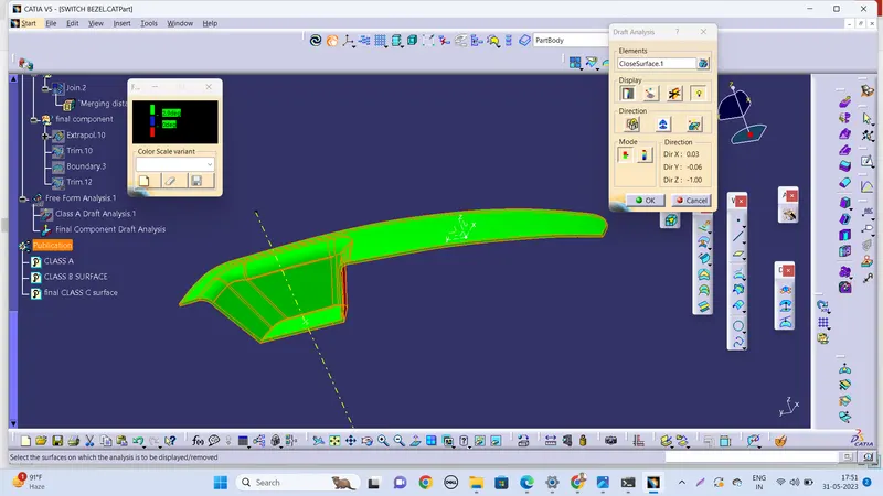
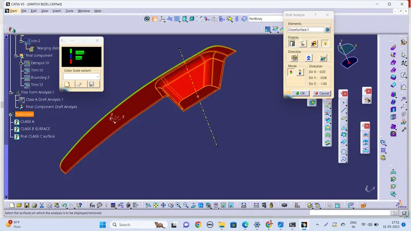
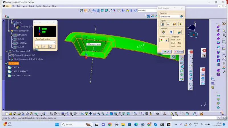
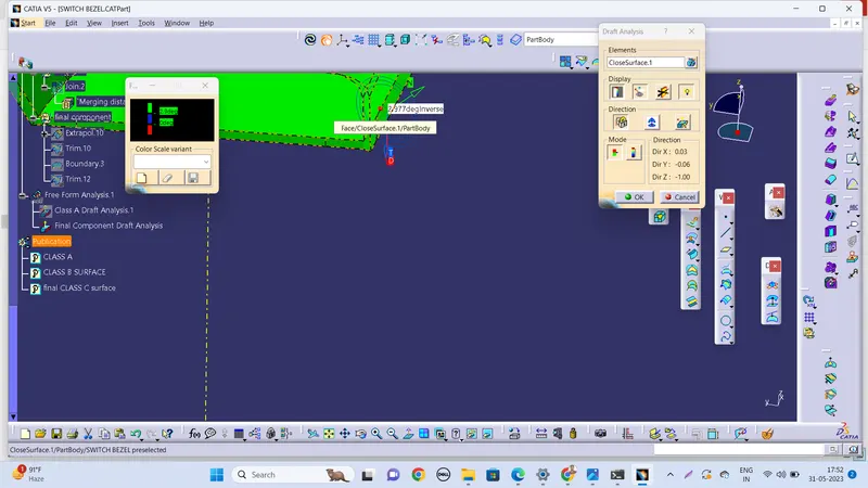
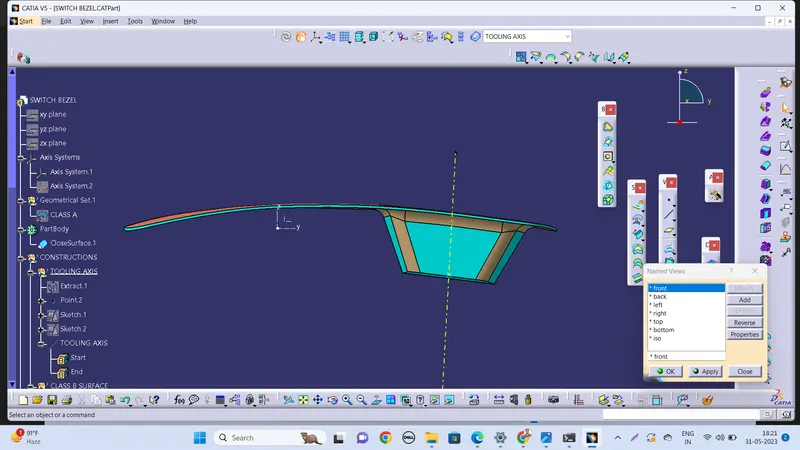
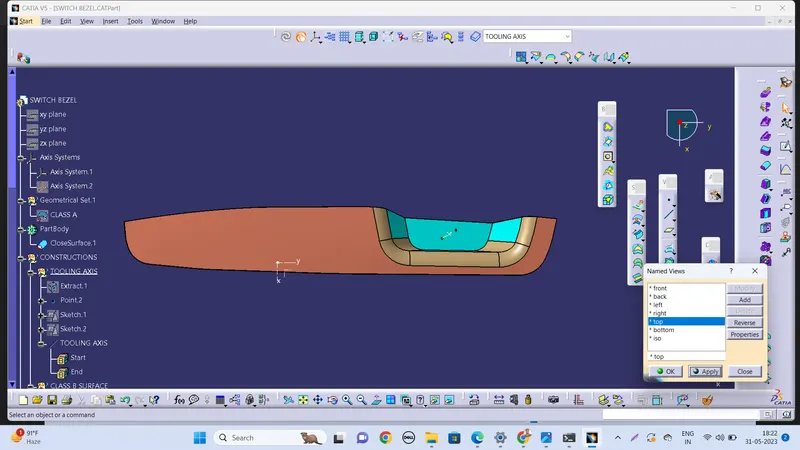
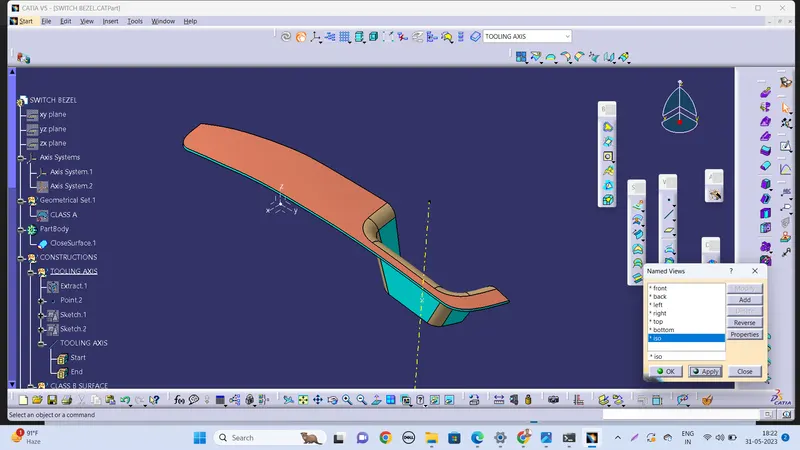
Screenshots of the solid model with the proper color code of the draft angle in various orientations (Isometric, Front, Side, and Top View)