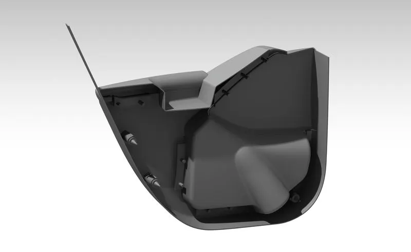
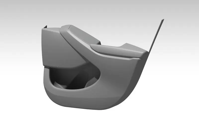
Development of a Door Trim panel
A Project Report on
Development of a Door Trim panel
INTRODUCTION
In this project, the focus lies on the design and development of a car's door panel, which serves as a crucial interface between the vehicle's interior and the inner workings of the door. The door panel is expected to fulfill a range of design specifications related to safety, aesthetics, and functionality. Additionally, it must align with the material theme of the dashboard and pillars while effectively concealing intricate electrical and mechanical components required for operating locks, windows, and other features.
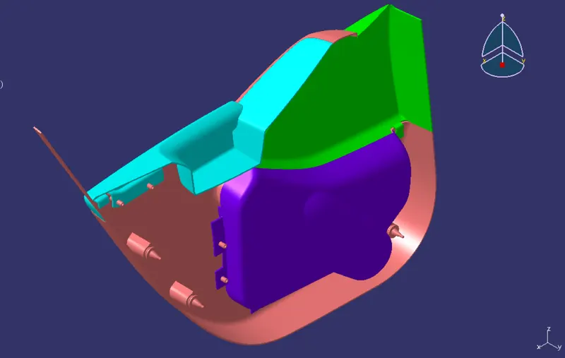
To create the door trim panel, the provided inner car door panel with a class A surface is divided into sub-parts, namely the lower substrate, inner map pocket, outer map pocket, and door armrest. These components are carefully designed to ensure a cohesive material theme throughout the car's interior while accommodating the necessary functionality and meeting safety requirements.
The project report outlines the step-by-step process and procedures employed in the development of plastic trims for car doors, utilizing the CATIA V5 surface workbench. It covers the creation of essential elements such as the main tooling axes, side core axes, Class B surface, Class C surface, and final closed body creations. Furthermore, a draft analysis is conducted to assess the manufacturability of the products using injection molding.
During the design of plastic trims, crucial factors such as functionality, safety, and styling are given significant consideration. These factors play a pivotal role not only in ensuring the door panel's effectiveness but also in influencing the vehicle's market appeal and sales. Moreover, the design is optimized to ensure cost-efficient manufacturability. By adhering to the principles of injection molding, the project successfully develops various plastic door trims, including map pockets, armrests, and the lower substrate, incorporating appropriate attachment features.
The meticulous integration of these trims with the door panel design enhances the overall user experience while contributing to the visual appeal and marketability of the vehicle.
OBJECTIVES:
The objectives of the project are as follows:
- Create a CAD model that aligns with the input requirements commonly followed by OEM and tier 1 companies. This involves incorporating the necessary design specifications and ensuring compatibility with the industry standards.
- Utilize the CATIA V5 tool to develop a solid body for the B Pillar Cover, based on the provided A Class Surface. The process includes adding appropriate thickness to the surface and incorporating ribs and locators as per the provided master section.
- Transform the received Class A surface, provided by the styling team, into a manufacturable product design. This objective involves utilizing the CATIA V5 surface workbench to develop a design that adheres to the OEM design standards. The focus is on converting the surface into a practical and feasible product design while maintaining the required aesthetic appeal.
METHODOLOGY:
Class A - Surface as an input
Class A surfaces in the automotive industry are highly significant as they represent the visible and physically meaningful surfaces of a product. These surfaces must meet stringent aesthetic standards and adhere to the desired design intent, ensuring a visually appealing and refined appearance.
Master sections play a crucial role in guiding the design requirements for automotive components. Acting as essential reference guides, master sections define the component packaging based on technical surfaces such as styling, concept, or Class A surfaces. These sections serve as a blueprint for achieving the desired form, fit, and function of the product, providing critical guidance during the design and development process.
In this project, the class A surface and the master section of each component are taken as input.
Components of the Door Trim Panel:
1. Upper Map Pocket
2. Lower Map Pocket
3. Door Arm Rest
4. Lower Substrate
1. Upper Map Pocket
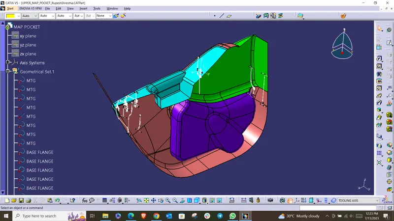
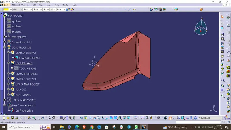
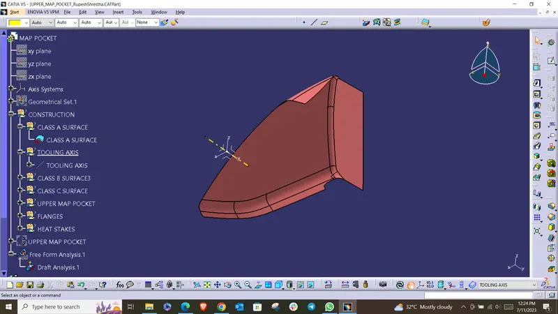
To begin the project, the Class A surface needed for each part from the main input is extracted. Then, it proceeds to work on each part individually. For instance, the Class A surface specifically for the map pocket component, is extracted as shown below.
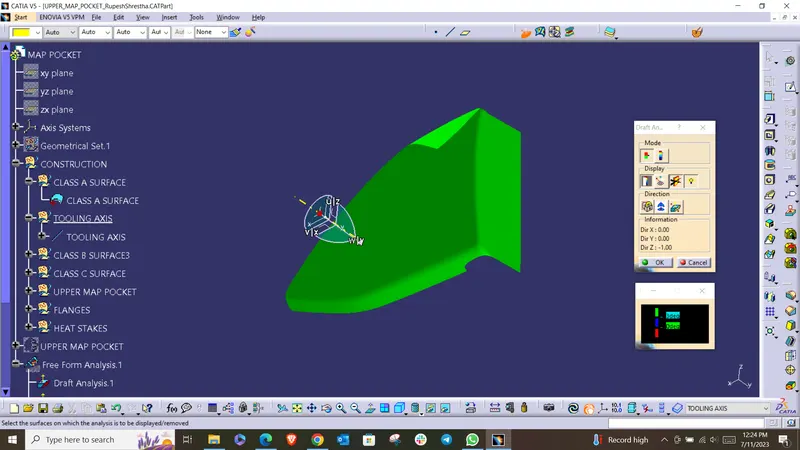
Next, the draft analysis of the class A surface is conducted to check if the product is manufacturable and if it can be pulled out of the injection machine without any friction or problem. The draft angle is kept at 3 degrees. The green colour on the Class A surface shows that it passes the draft analysis.
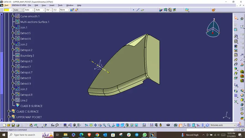
After the successful draft analysis of the upper map pocket, the B surface is developed by offsetting the class A surface as shown in the following diagram. It is the surface inside the component which is not visible from the outside.
Now, to connect the Class A surface and the B surface, a C surface is made by sweeping the surface along the edge of the Class A surface such that it intersects with both surfaces.
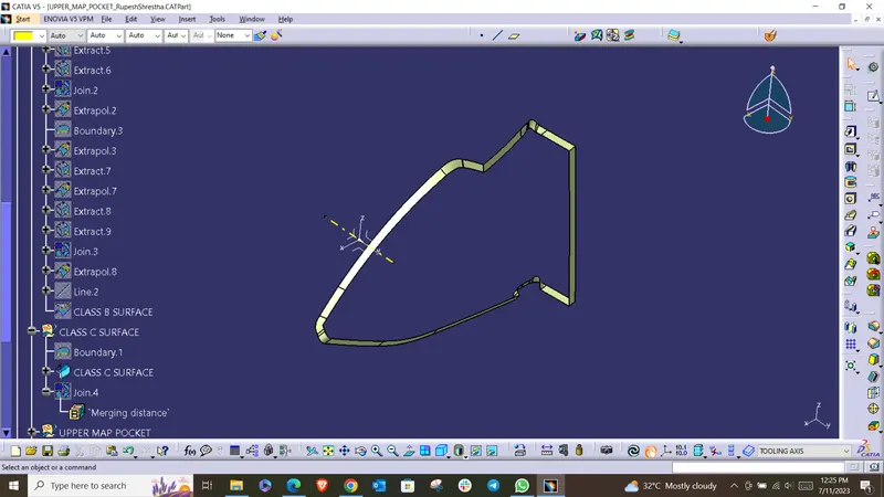
Then, it is trimmed with both surfaces such that they combine to form a single surface with no openings, ready to make a solid body out of it.
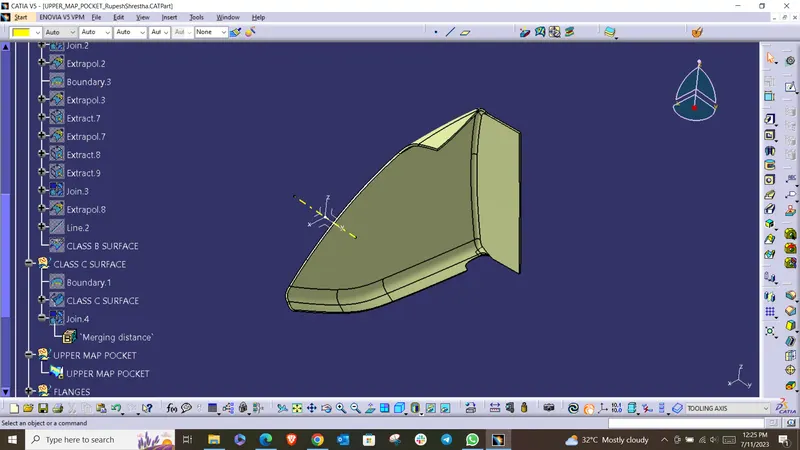
After this, the solid body is created out of the closed surface. Once the solid body is made, the flanges are made on the map pocket as it is required for support and to assemble or fit with other components of the door trim panel. The flanges are created first by creating a surface for the flange, creating a body from it, and using revolved surface to trim the surfaces of the flanges to create a complete flange surface. Finally, the flange is created by doing the boolean operation with the main body.
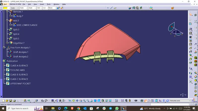
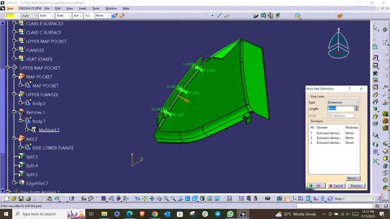
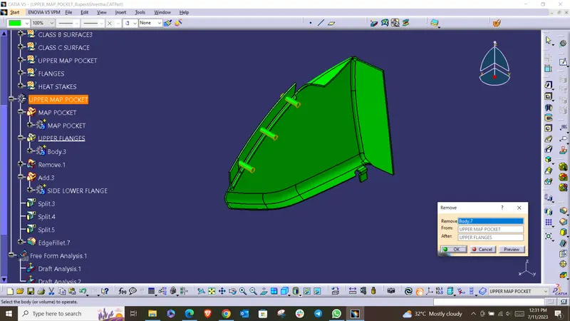
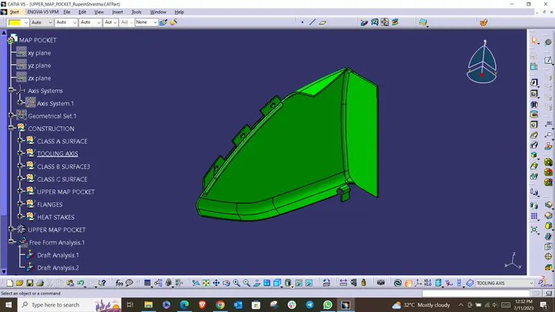
In this way, the upper map pocket is created with the flanges.
2. Lower Map Pocket:
To begin the lower map pocket, the Class A surface for the Lower map pocket component is extracted as shown below.
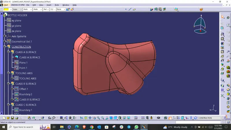
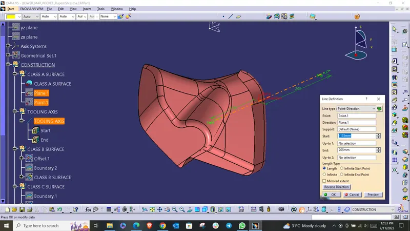
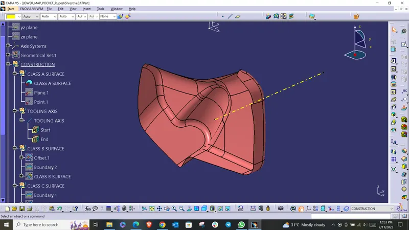
Next, the draft analysis of the class A surface is conducted to check if the product is manufacturable and if it can be pulled out of the injection machine without any friction or problem. The draft angle is kept at 3 degrees. The green colour on the Class A surface shows that it passes the draft analysis.
If there's any red colour, it indicates that the draft angle has to be increased by the Class A surface designer.
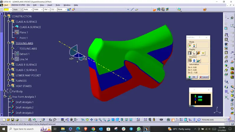
After the successful draft analysis of the upper map pocket, the B surface is developed by offsetting the class A surface as shown in the following diagram. It is the surface inside the component which is not visible from the outside.
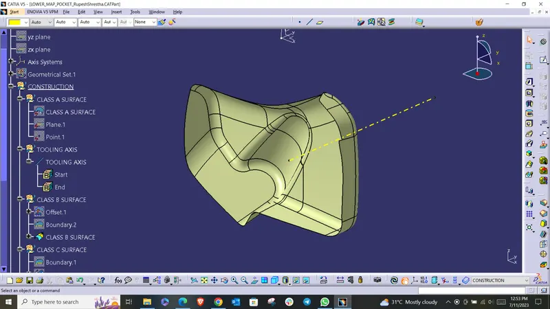
Now, to connect the Class A surface and the B surface, a C surface is made by sweeping the surface along the edge of the class A surface such that it intersects with both surfaces.
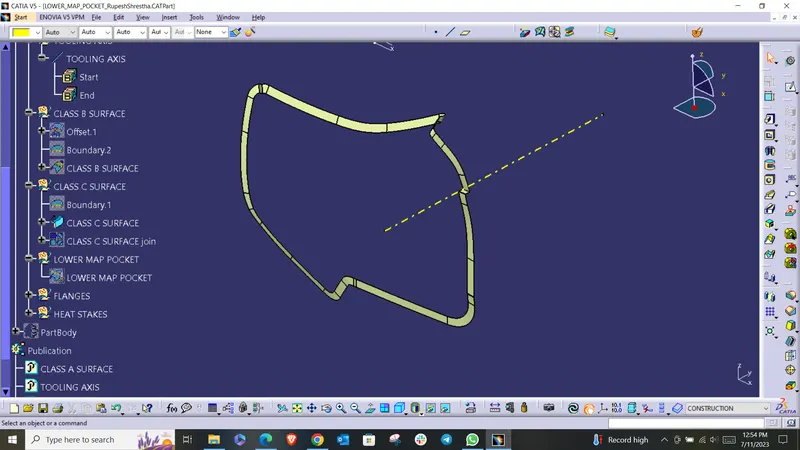
Then, it is trimmed with both surfaces such that they combine to form a single surface with no openings, ready to make a solid body out of it.
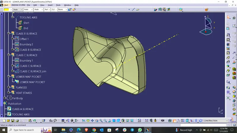
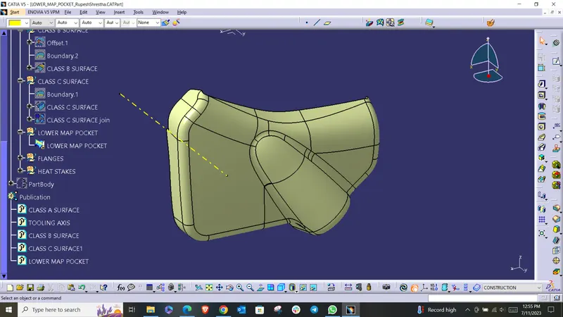
After this, the solid body is created out of the closed surface. Once the solid body is made, the flanges are made on the map pocket as it is required for support and to assemble or fit with other components of the door trim panel. The flanges are created first by creating a surface for the flange, creating a body from it, and using revolved surface to trim the surfaces of the flanges to create a complete flange surface. Finally, the flange is created by doing the boolean operation with the main body.
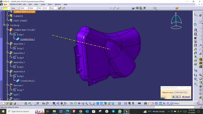
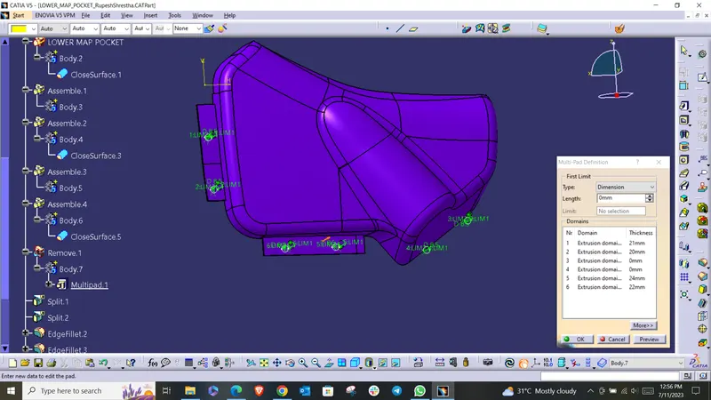
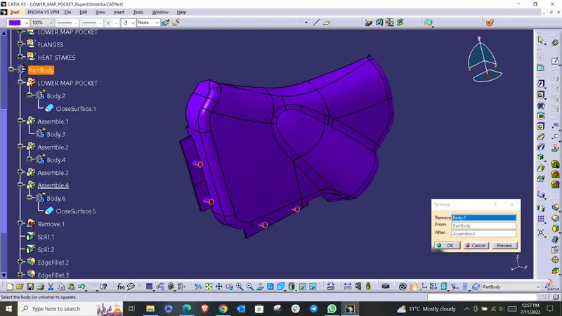
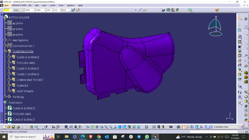
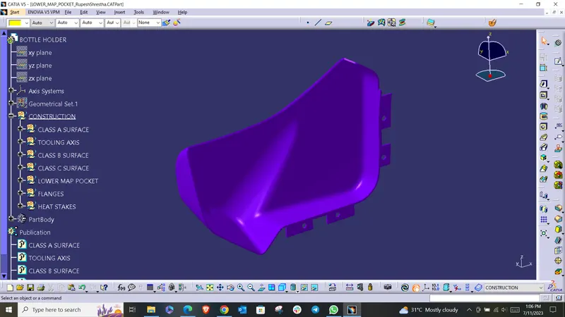
In this way, the lower map pocket is created with the flanges.
3. Door Armrest:
To begin the design of door armrest, the Class A surface for the armrest is extracted as shown below.
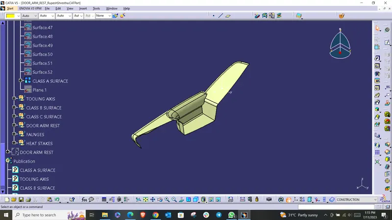
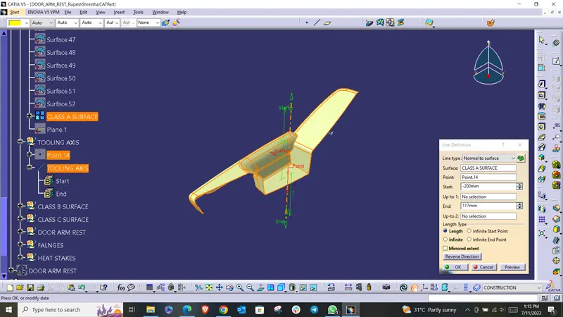
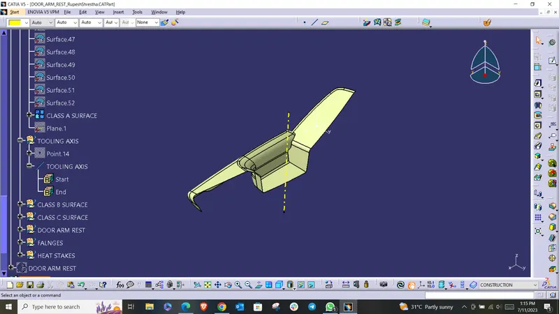
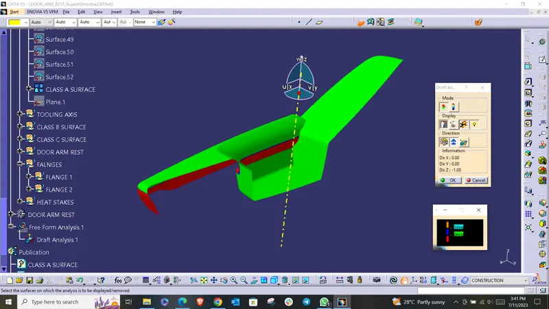
Next, the draft analysis of the class A surface is conducted to check if the product is manufacturable and if it can be pulled out of the injection machine without any friction or problem. The draft angle is kept at 3 degrees. The green colour on the Class A surface shows that it passes the draft analysis.
If there's any red colour, it indicates that the draft angle has to be increased by the Class A surface designer.
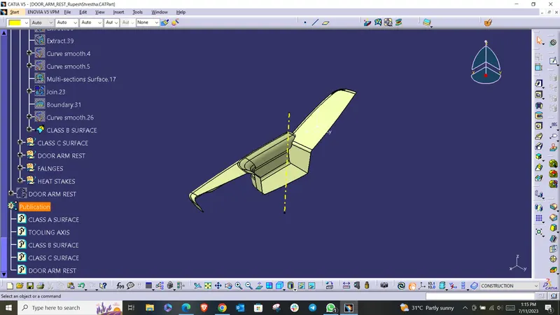
After the successful draft analysis of the upper map pocket, the B surface is developed by offsetting the class A surface as shown in the following diagram. It is the surface inside the component which is not visible from outside.
Now, to connect the Class A surface and the B surface, a C surface is made by sweeping the surface along the edge of the class A surface such that it intersects with both surfaces.
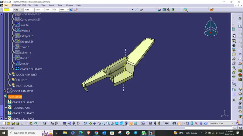
Then, it is trimmed with both surfaces such that they combine to form a single surface with no openings, ready to make a solid body out of it.
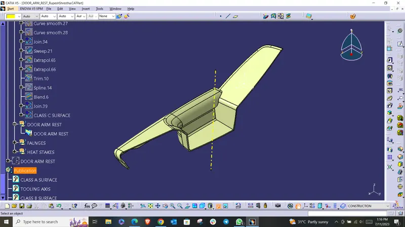
After this, the solid body is created out of the closed surface. Once the solid body is made, the flanges are made on the edges of the armrest as it is required for support and to assemble or fit with other components of the door trim panel. The flanges are created first by creating a surface for the flange, creating a body from it, and using revolved surface to trim the surfaces of the flanges to create a complete flange surface. Finally, the flange is created by doing the boolean operation with the main body.
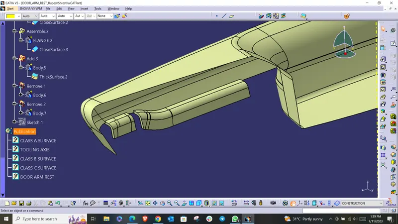
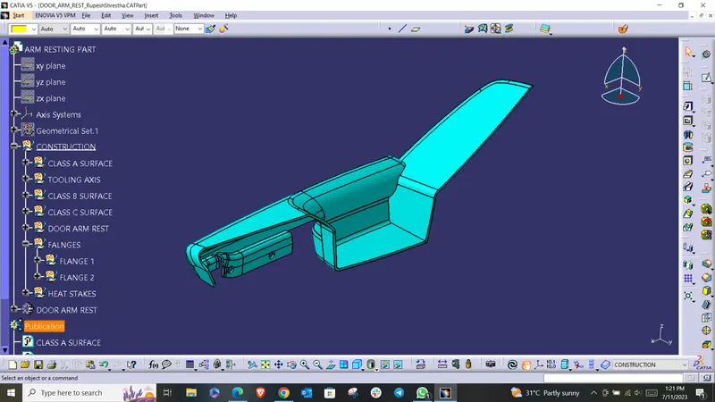
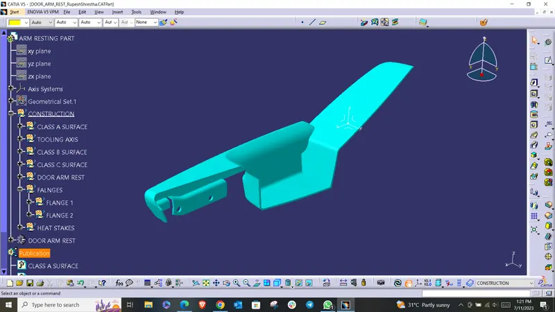
In this way, the armrest of the door trim is created with the flanges.
4. Lower Substrate:
To begin the design of the lower substrate, the Class A surface for the lower substrate is extracted as shown below.
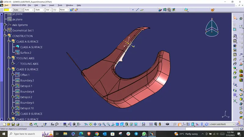
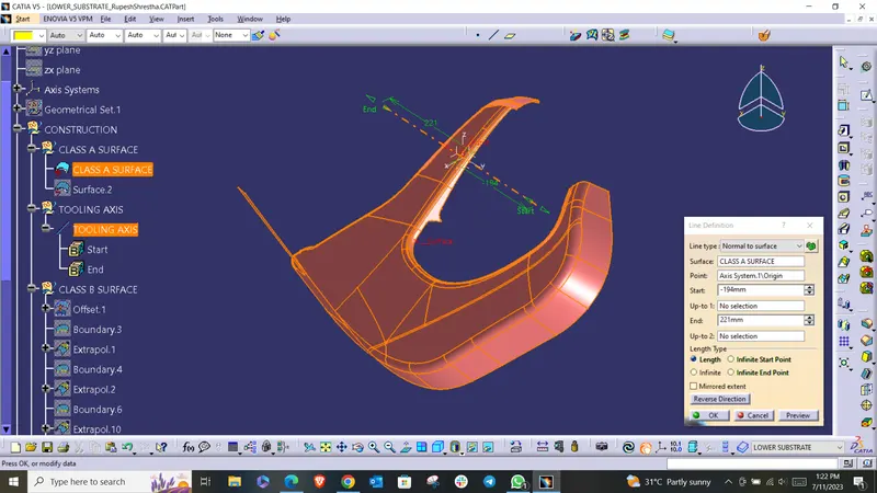
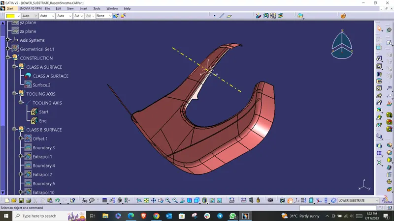
Next, the draft analysis of the class A surface is conducted to check if the product is manufacturable and if it can be pulled out of the injection machine without any friction or problem. The draft angle is kept at 3 degrees. The green colour on the Class A surface shows that it passes the draft analysis.
If there's any red colour, it indicates that the draft angle has to be increased by the Class A surface designer.
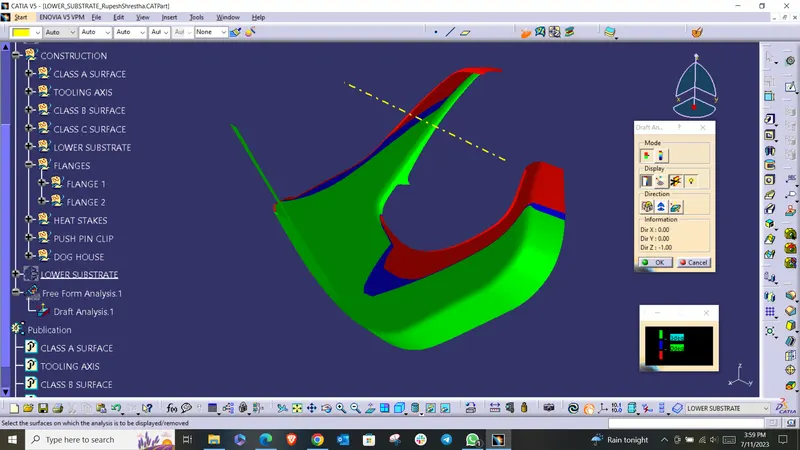
After the successful draft analysis of the lower substrate, the B surface is developed by offsetting the class A surface as shown in the following diagram. It is the surface inside the component which is not visible from the outside.
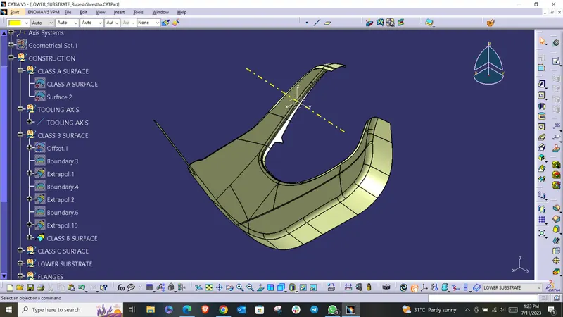
Now, to connect the Class A surface and the B surface, a C surface is made by sweeping the surface along the edge of the Class A surface such that it intersects with both surfaces.
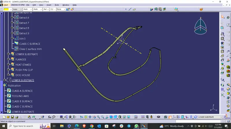
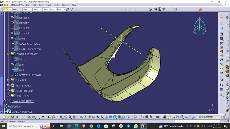
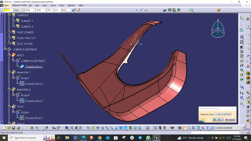
Then, it is trimmed with both surfaces such that they combine to form a single surface with no openings, ready to make a solid body out of it.
Flanges, Heat stakes, and dog houses:
After this, the solid body is created out of the closed surface. Once the solid body is made, the flanges are made on the edges of the lower substrate as it is required for support and to assemble or fit with other components of the door trim panel.
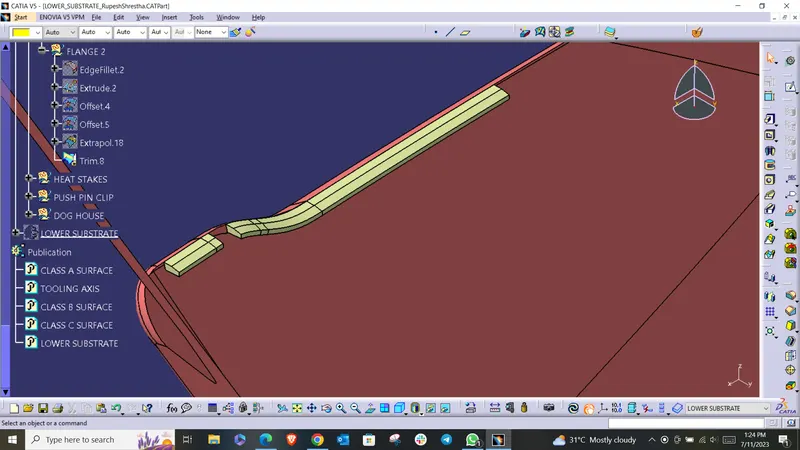
After the flanges are created, the heat stakes are made on the lower substrate as it is required to assemble with other components of the door trim panel. Flanges are not always suitable for every part of the component. This is why heat stakes and dog houses may be required as per the component. Heat stakes assemble the two components by joining them by entering the heat stakes to their location and melting them to lock the position.
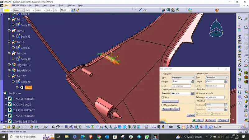
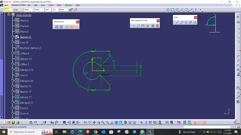
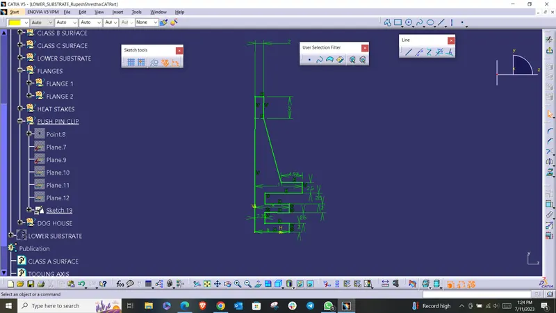
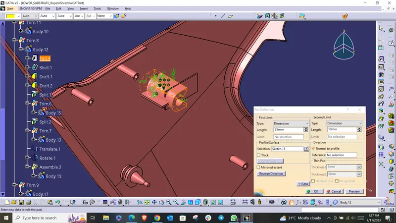
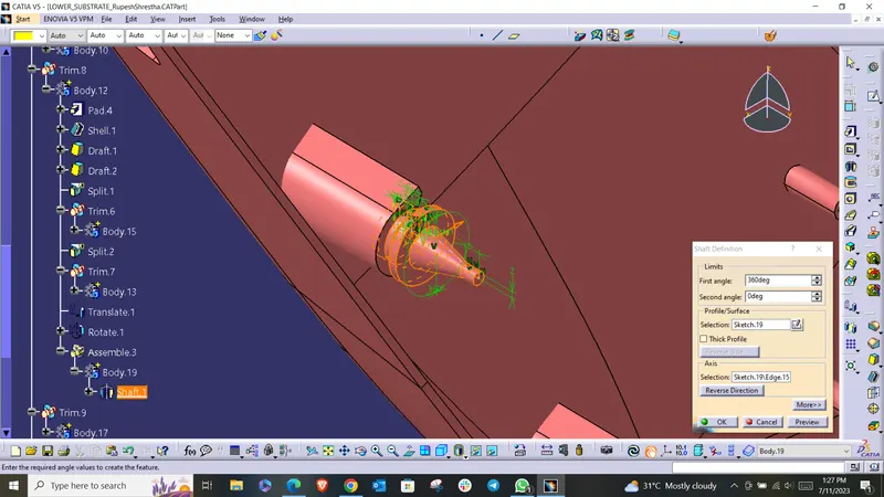
Afterward, the dog houses along with the push pin clips. First, the sketches for the dog house base are drawn and the extrusion is performed. Later, the sketch for the push pin clip is drawn above the doghouse and the surface is revolved to create the push pin. After that, the solid body is created out of the hollow surface.
 x
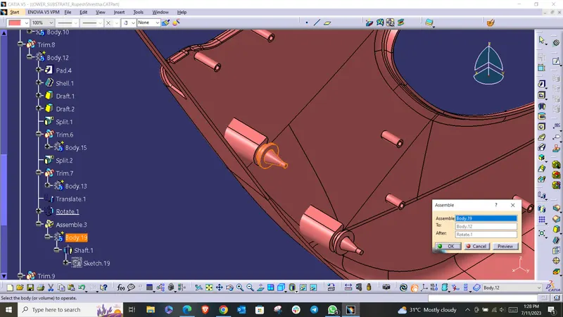
Finally, the heat stakes and the dog houses are added to the main body by doing the boolean operation with the main body. 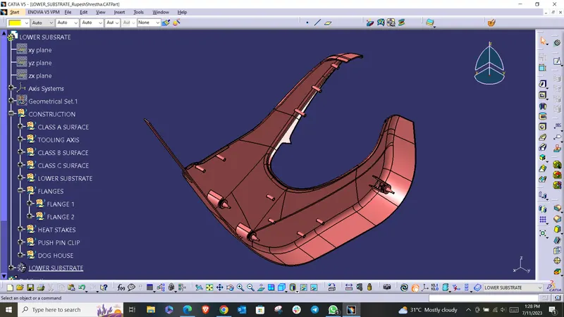
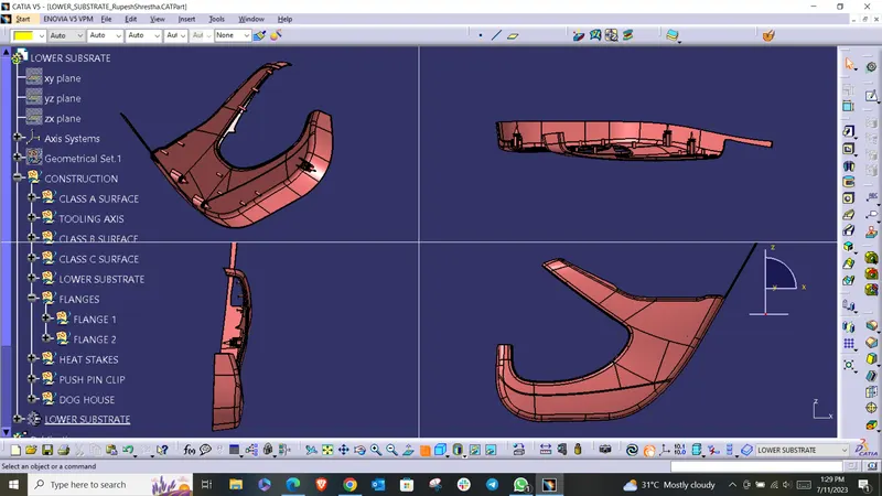
In this way, the lower substrate is created with the flanges, heat stakes, and dog houses.
ASSEMBLY DESIGN:
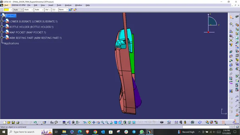
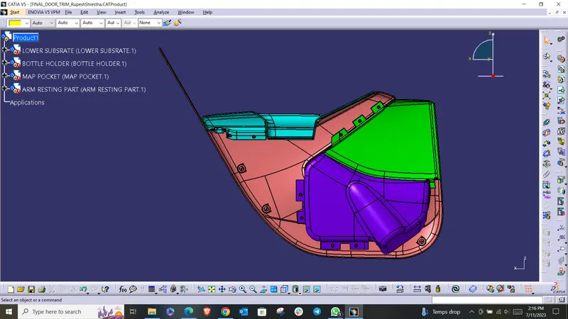
After all the individual components are completed, the assembly of those components is made. In CATIA, the assembly file is called and saved as CATProduct. To assemble the components, first, the assembly design file is created and the required components (upper map pocket, lower map pocket, armrest, and lower substrate) are imported into the assembly. The assembly file is created once the components are placed in their positions. While making the assembly file, the position of the flanges, push pins, heat stakes, and dog houses are checked and aligned properly. Once their correct positions are ensured, the assembly file is ready and the development of the door trim panel is complete.
Front view:
Right side view:
Left side view:
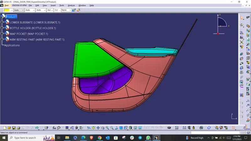
Isometric view:
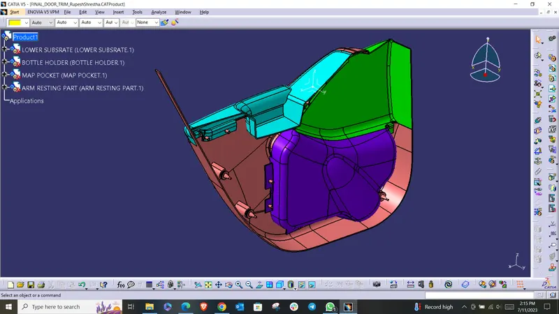
Final Images: