Week 12- Final project
AIM
- Development of a Door Trim panel
Creation of CAD model considering following inputs as like in OEM and tier1 companies
- a) Class A surface
- b) Nominal thickness : Refer master sections
- c) Attachment strategy
Find a attachment strategy for the door panel complete work.
Use Push pin with Dog house for Lower substrate – Door panel attachment
Use heat stakes for part to part attachment
DEVELPOPMENT OF DOOR TRIM PANEL
The main parts of door trim panel are Lower substrate,Map pocket,Bottle holder and Arm rest.This parts assemble to get the final product door trim panel.The given class A surface and master sections used to create the parts.
TOOLING AXIS FOR CLASS A SURFACE
Design Engineer analyse the Class A Surface and create the best possible tooling direction for error-free production of the component.Also ensure that the surface has minimum draft angle with respect to the tooling axis for the smooth ejection of the Component from the mould.
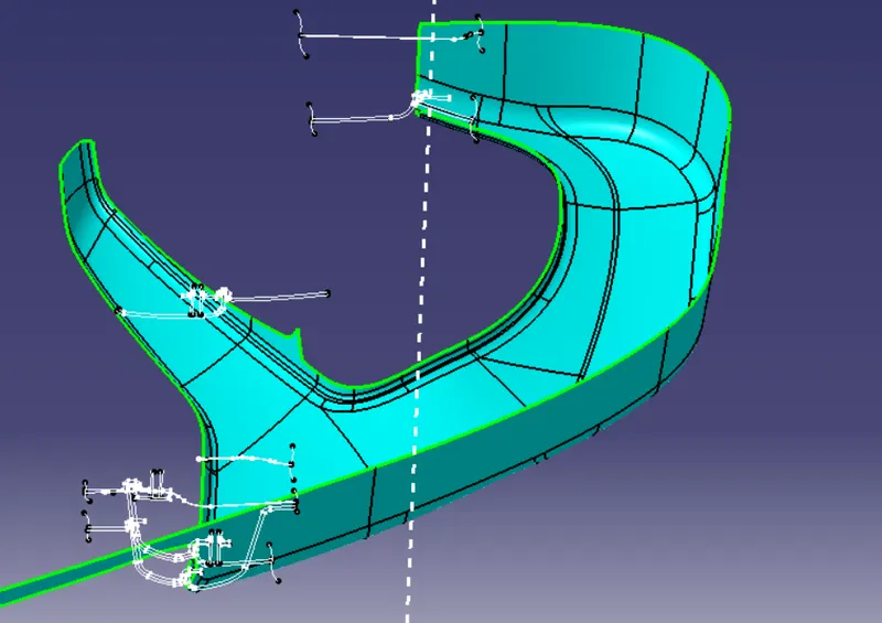
LOWER SUBSTATE
Tooling axis for the lower substrate is created in Y-direction by following the bisecting method .In this direction the mold opens and closes.
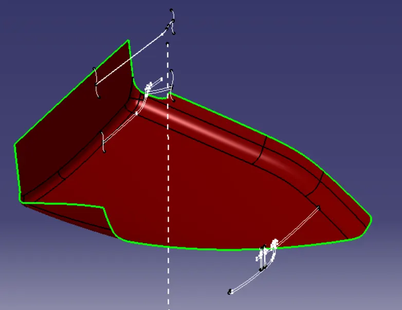
MAP POCKET
Tooling axis for the map pocket created in Y direction .here point and direction method is used to create the main tooling axis .
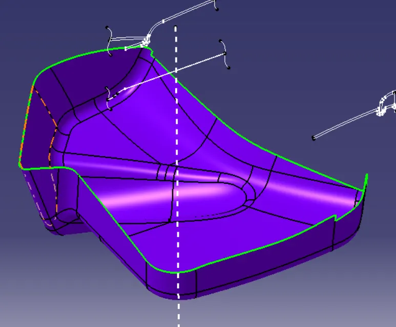
BOTTLE HOLDER
Tooling axis for the map pocket created in Y-direction.bi-secting method is used to create the tooling axis.
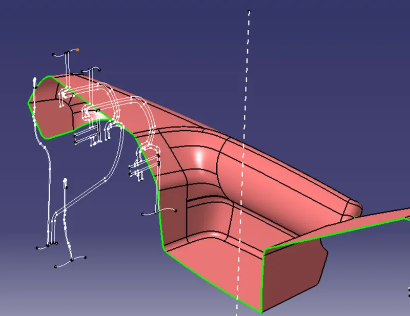
ARM REST
Tooling axis for the arm rest created in Z-direction .Here bisecting method is used to create the main tooling axis .
DRAFT ANALYSIS OF CLASS A SURFACE
Check the draft analysis of the given class A surface along the tooling direction to ensure the part has minimum draft angle (3 degree) in all faces.
LOWER SUBSTRATE
The class A surface of lower substrate clearing the draft along tooling direction.
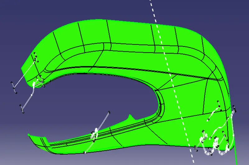
MAP POCKET
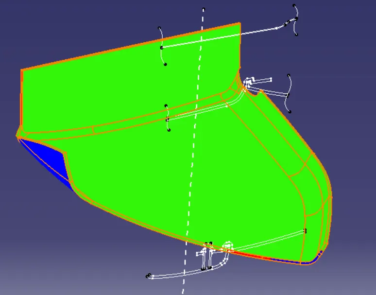
BOTTLE HOLDER
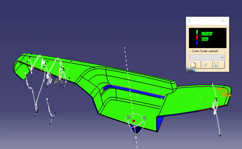
Tooling axis for the bottle holder created in Y-direction .Draft analysis of bottle holder shown in fig. Here Some portions of given class A surface not clearing the minimum draft .So Tooling axis created in different methods and perform the draft analysis and finally it conclude that some improvment need in the given class A surface to maintain the minimum draft .
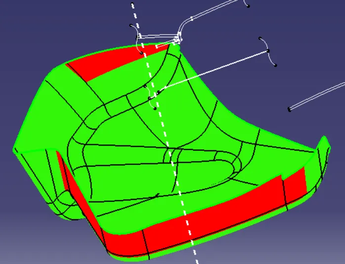
ARM REST
Draft analysis perfomed on the given class A surface along tooling axis shown in fig .Here Some portions of given class A surface not clearing the minimum draft .So Tooling axis created in different methods and perform the draft analysis finally it clear that some improvement needed in the given class A surface to maintain minimum draft angle .
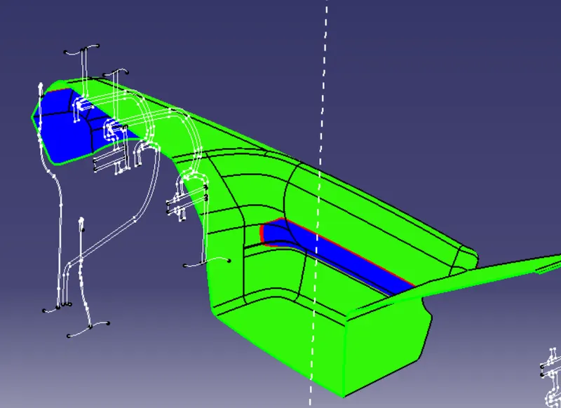
CLASS B SURFACE
The class B surface is the surface where all the engineering features attached.class B surface is created by offseting the class A surface in required thickness 2.5 mm(from master section).Extract,extrapolation and trim operations used to create the class B surface.
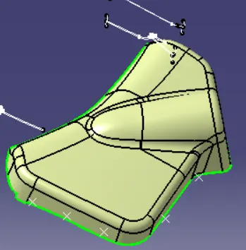
class B surface of bottle holder
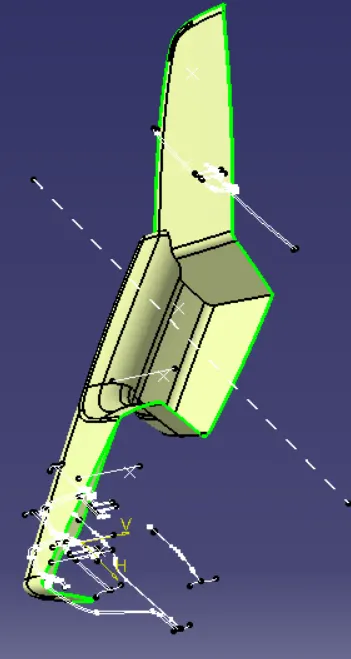
class B surface of arm rest
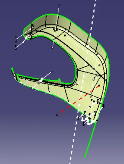
class B surface of Lower substrate
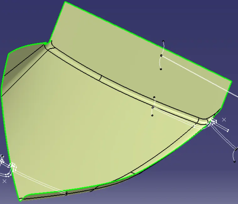
class B surface of map pocket
CLASS C SURFACE
Class C surface connecting the class A and B surfaces. Class C Surface is generated by using Sweep operation (with referance surface and with draft direction).Class C surface created by class A surface as a referance.
- Then join the class A surface with class C surface
- Finally trim with class B to get the closed surface of component
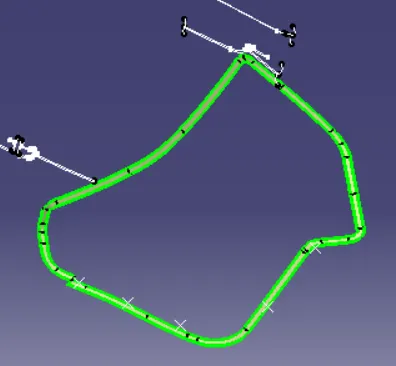
class C surface of bottle holder
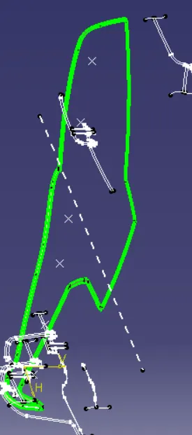
class C surface of arm rest

class C surface of Lower substrate
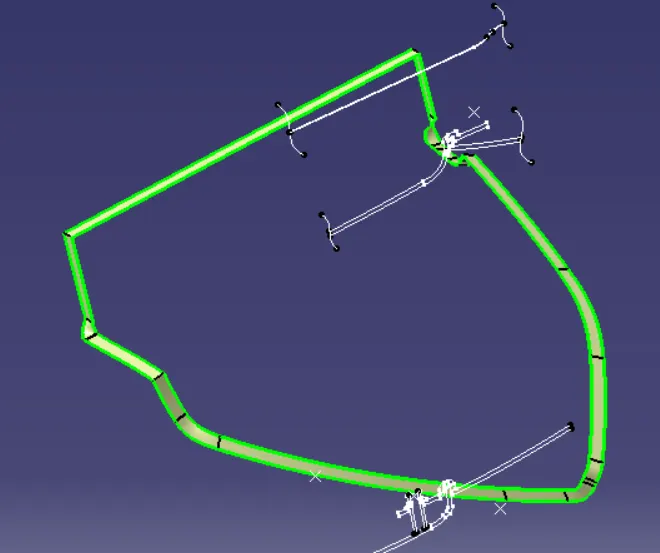
class C surface of map pocket
ATTACHMENT FEATURE CREATION
HEAT STAKES
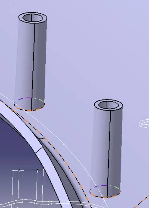
Heat staking also known as thermoplastic staking is the process of joining two dissimilar materials together. In heat staking we use local heating and cooling to raise the temperature of plastic components and allow plastic reforming to be carried out. This reforming can be used in a wide variety of applications.
Here heat stakes created with draft 0.5 degree, fillet radius is 0.25mm and wall thickness is 1.5mm (0.6*2.5) .heat stakes designed by following the design rules and master section.
LOCATORS
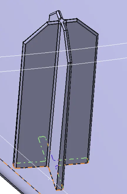
Typically, locating pins are used for controlled, fine tolerance positioning of a work piece.
A 2-way locating pin restricts motion along 1 axis (or 2 degrees of Freedom), like a round pin in a slot. Likewise, a 4-way pin restricts 4 degrees of freedom along 2 axes. A round locating pin located concentrically in a hole is a common application of a 4-way pin, and helps to further secure the piece
Here 4-way locator created with thickness 1mm ,draft 0.5 degree and the fillet value is 0.25 mm
DOG HOUSE
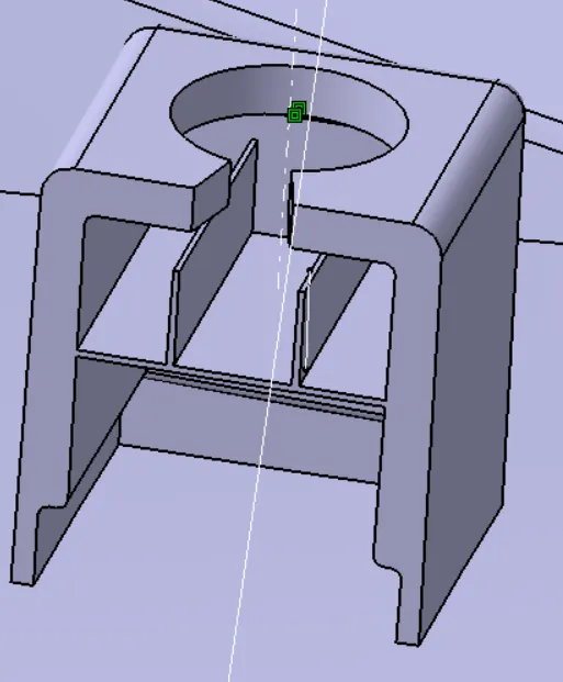
doghouse created by considering the design rules .height of b is between 3-6 mm .doghouse wall thickness at the intersion is 0.78 mm. It is less than 40% of main wall thickness(0.4*2.5=1mm). Doghouse wall thickness at the intersection of the part wall ( C ) should be 40% or less than the main wall stock.
DRAFT ANALYSIS OF FEATURE CREATION
DRAFT ANALYSIS OF HEAT STAKES AND LOCATORS
Here heat stakes and locator created with minimum draft 0.5 degree.
DRAFT ANALYSIS OF DOG HOUSE
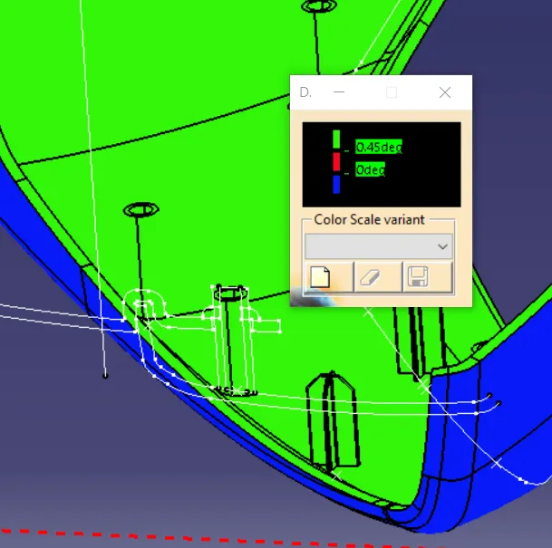
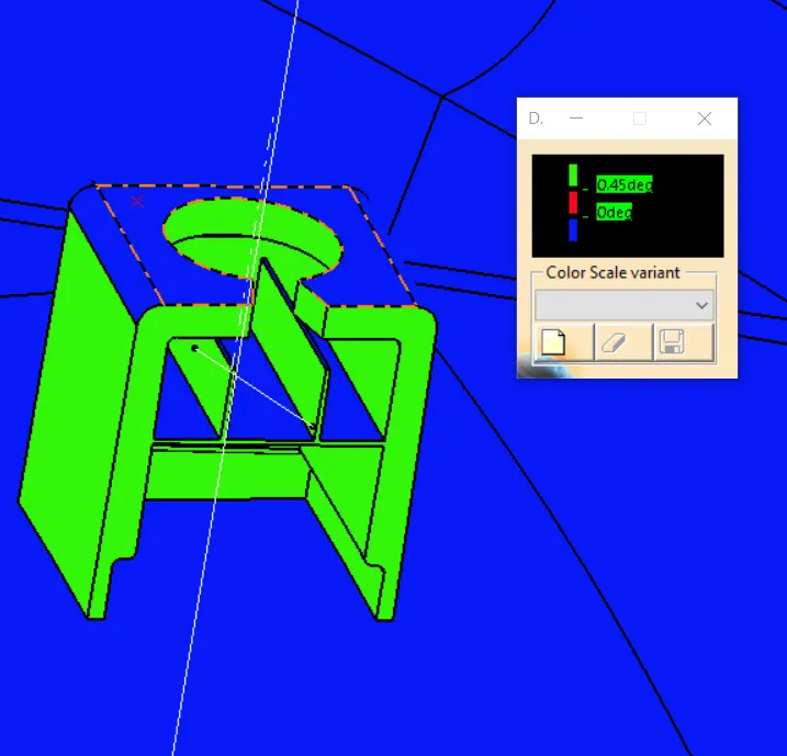
The below image shows the draft analysis of dog house along main tooling axis.it clearing the minimum draft angle of 1.5 degree.
The below figure shows the draft analysis of dog house along side core axis .dog house has minimum draft of 0.5 degree.
DRAFT ANALYSIS OF FLANGES
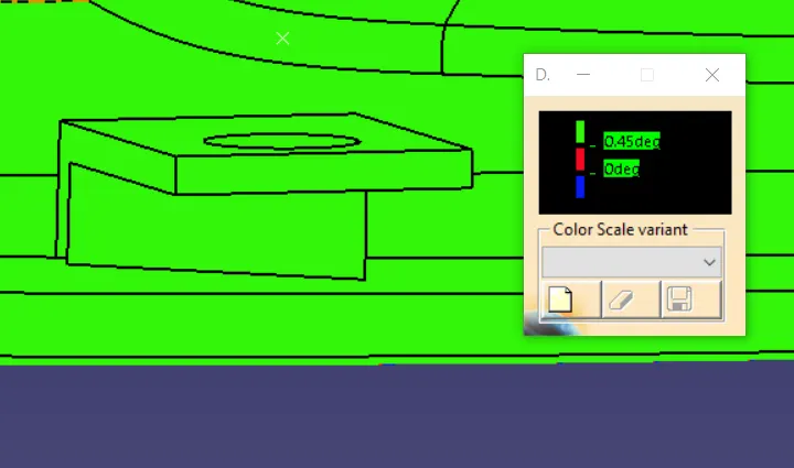
Here edges of flanges have minimum draft angle of 0.5 dergee.
DRAFT ANALYSIS OF THE SOLID PARTS
Lower substrate
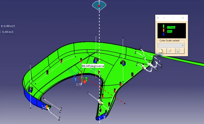
The below figure shows the draft analysis of lower substrate .smaller portion of the class c surface not clearing the minimum draft angle of 3 degree due to some errors in class A surface.
map pocket
shown in the below figure .Here some portions of class c surface not clearing the draft due to error in class A surface .class c surface is created from class A surface as a reference .
Bottle holder
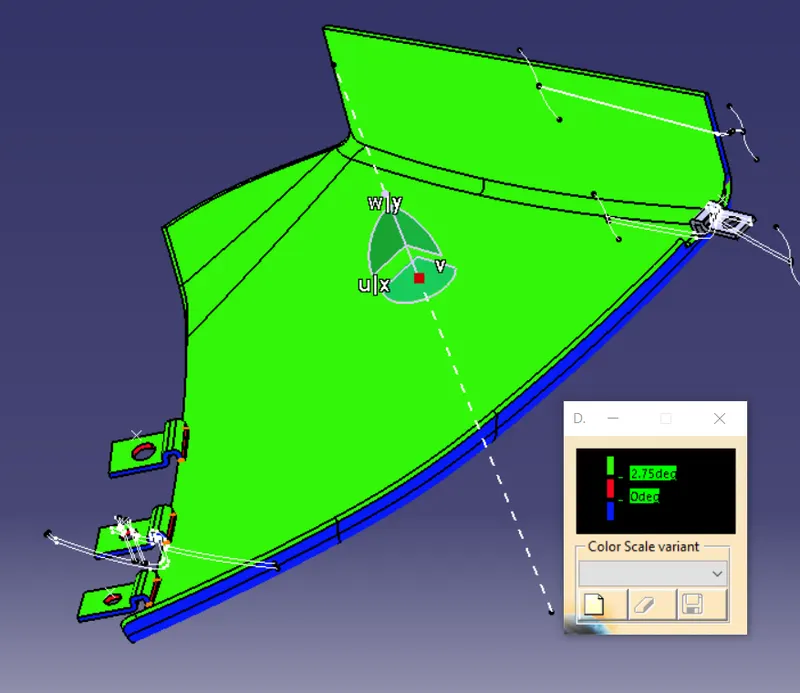
The below figure shows the draft analysis of bottle holder.The given class A surface not having the minimum draft so the Bottle holder not clearing draft .
Arm rest
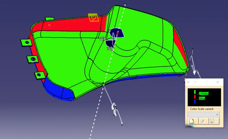
The below figure.shows the draft analysis of arm rest .class B and class C surface is created from class A surface .here some areas of arm rest not clearing the minimum draft.so it conclude that modification in class A surface is required.
ASSEMBLY OF PUSH PIN
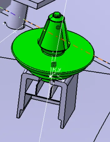
The below figure shows the assembly of push pin into the dog house.Coincidence constrains used to fix the push pin.
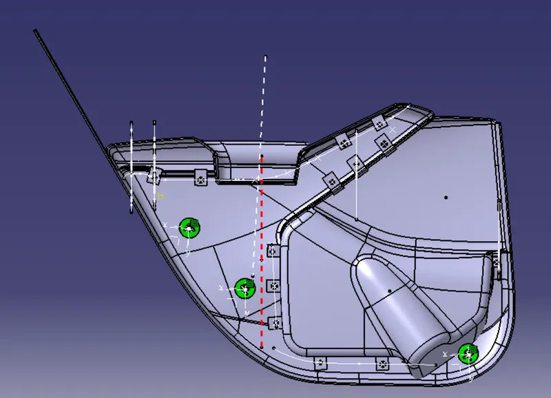
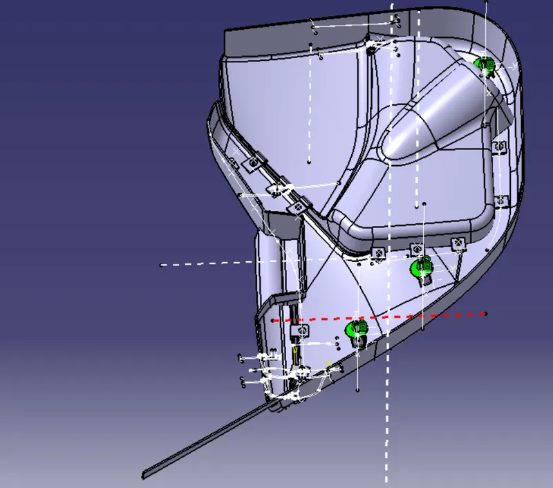
DIFFERNT VIEWS OF DOOR TRIM PANEL
CONCLUSION
Door trim panel created by considering the master section and attachment stratergy.Attachment features created by considering the design rules.