Week 12- Final project
AIM:
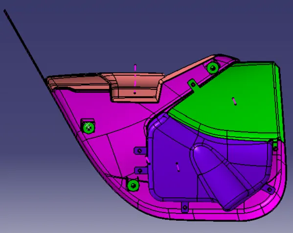
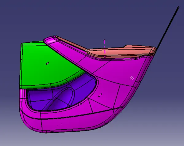
To design and development of vehicle interior door trim using Catia V5 with given class A surface along with Master section. Also create the Side Attachment features as per design rules.
OBJECTIVE:
- To create thickened part using master section for reference
- To create the mounting features as per design guidelines in the industry and with master sections
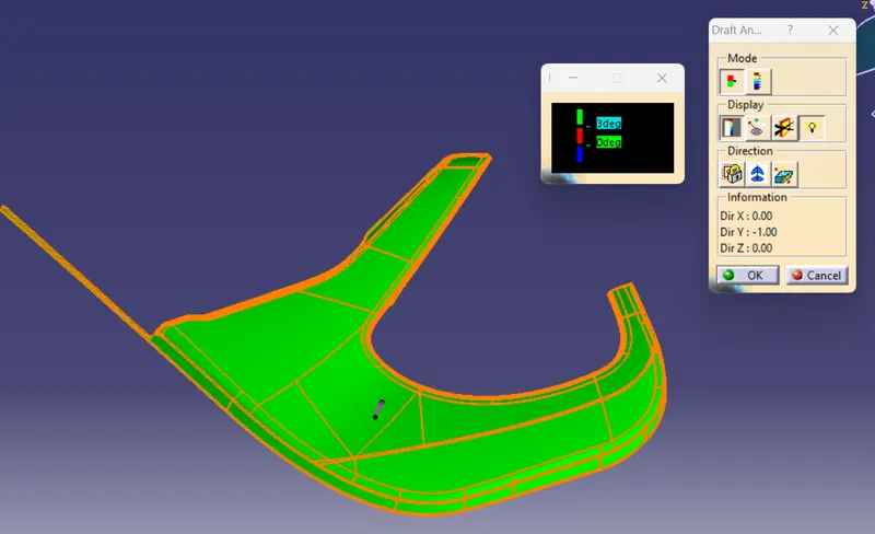
- To perform Draft analysis & Tooling analysis
INTRODUCTION:
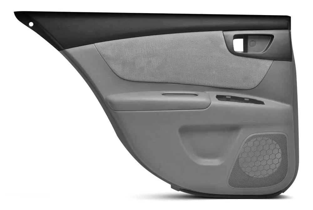
The door panel is the interface between the interior of the car and the inner workings of the door. Generally the door panel is divided into parts for easy designing like arm rest, map pocket, lower substrate. These require one of the toughest requirement among the interior parts of the car. This should be designed to with stand the load while being less than 2mm in thickness and also to protect the occupants during collisions.
METHODOLOGY:
Part -01 : Lower Substrate
Creating the Tooling Axis
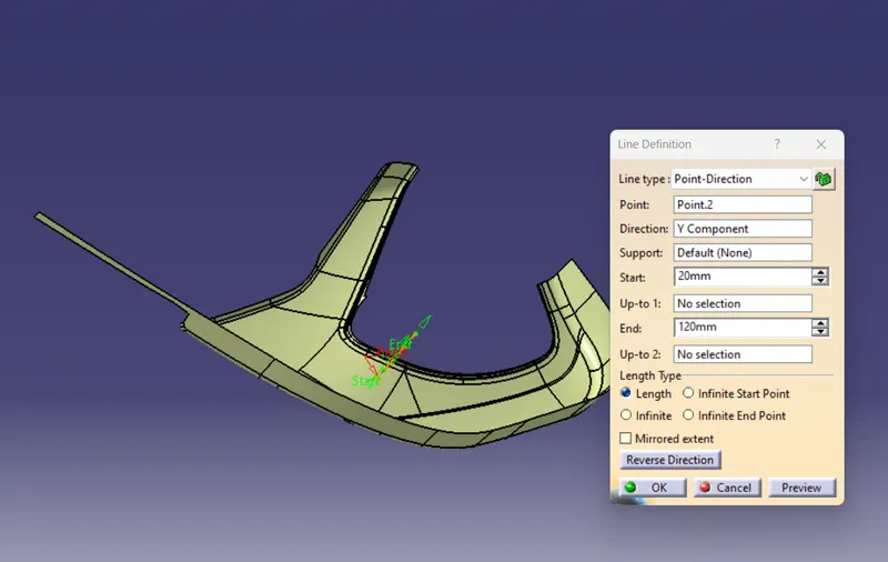
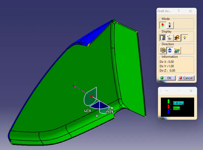
The tooling direction is used to find the direction in which the part is removed from the core and cavity. The draft angle should be positive to the tooling axis to manufacture the component easily. The step by step procedure of creating the tooling axis is given below.
1. Creating the tooling axis : for Lower Substrate by create a point on surfaces respectively to the 0 value. It automatically create at mid surface and generate the line to the direction of y axis.
 .
.
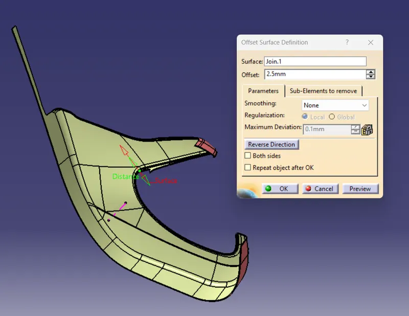
2.Creation Of Class B Surface
- Now, Class B surface has to be created. For this, multiple extract is used to extract surface in a single operation. Surfaces obtained are the offset for 2.5mm.
- The Unfilled areas have to be offset separately and needs to be filled with multisection and other surface joining commands and join them together.
- Check the B surface by boundary command to make sure there is no gap in the surface.
3.Creation Of Class C Surface
- Now class C surface has to be created and it is created from the boundaries obtained from the Class A surface. This boundary is provided as the input curve for sweep command. Using sweep command, class C surface is created.
- Appropriate sweep is the provided considering the flash and considering manufacturing procedures. Surfaces are extrapolated if necessary.
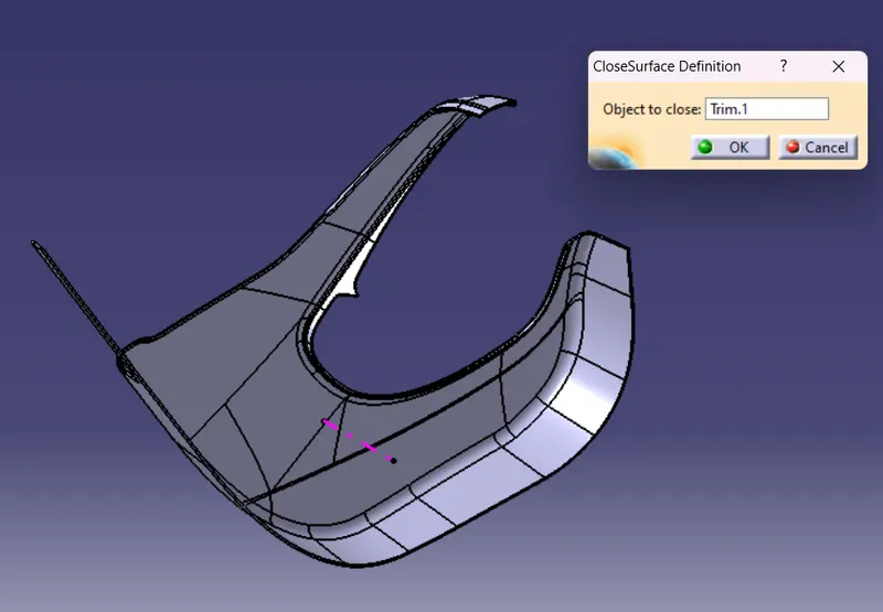
4. Creation Of Closed Body
- Closed surface command is performed with the help of part workbench and later the draft analysis is performed.
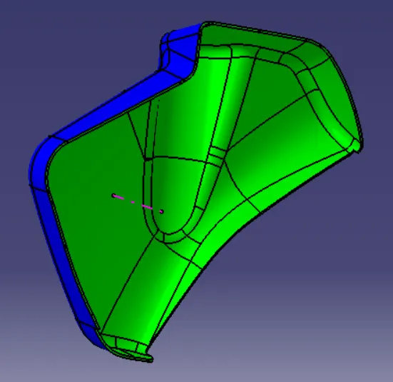
5. Draft Analysis Of Closed Body
Part -02 : Map Pocket
Creating the Tooling Axis
The tooling direction is used to find the direction in which the part is removed from the core and cavity. The draft angle should be positive to the tooling axis to manufacture the component easily. The step by step procedure of creating the tooling axis is given below.
1. Creating the tooling axis : for Lower Substrate by create a point on surfaces respectively to the 0 value. It automatically create at mid surface and generate the line to the direction of y axis.
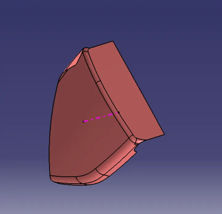
2.Creation Of Class B Surface
- Now, Class B surface has to be created. For this, multiple extract is used to extract surface in a single operation. Surfaces obtained are the offset for 2.5mm.
- The Unfilled areas have to be offset separately and needs to be filled with multisection and other surface joining commands and join them together.
- Check the B surface by boundary command to make sure there is no gap in the surface.
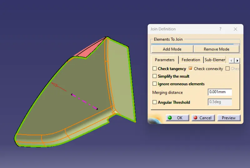
3.Creation Of Class C Surface
- Now class C surface has to be created and it is created from the boundaries obtained from the Class A surface. This boundary is provided as the input curve for sweep command. Using sweep command, class C surface is created.
- Appropriate sweep is the provided considering the flash and considering manufacturing procedures. Surfaces are extrapolated if necessary.
4. Creation Of Closed Body
- Closed surface command is performed with the help of part workbench and later the draft analysis is performed.
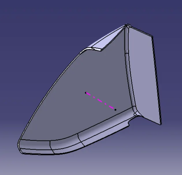
5. Draft Analysis Of Closed Body
Part -03 : Arm Rest
Creating the Tooling Axis
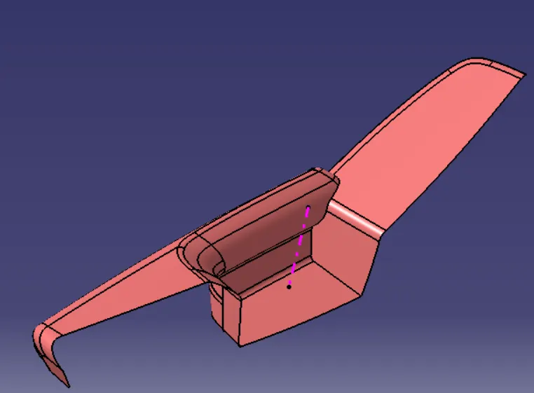
The tooling direction is used to find the direction in which the part is removed from the core and cavity. The draft angle should be positive to the tooling axis to manufacture the component easily. The step by step procedure of creating the tooling axis is given below.
- Creating the tooling axis: for arm rest tooling is created by creating a point on surfaces respectively to the 0 value. It automatically create at mid surface and generate the line to the direction of y axis.
2.Creation Of Class B Surface
- Now, Class B surface has to be created. For this, multiple extract is used to extract surface in a single operation. Surfaces obtained are the offset for 2.5mm.
- The Unfilled areas have to be offset separately and needs to be filled with multisection and other surface joining commands and join them together.
- Check the B surface by boundary command to make sure there is no gap in the surface.
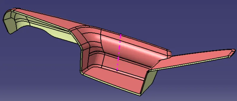
3.Creation Of Class C Surface
- Now class C surface has to be created and it is created from the boundaries obtained from the Class A surface. This boundary is provided as the input curve for sweep command. Using sweep command, class C surface is created.
- Appropriate sweep is the provided considering the flash and considering manufacturing procedures. Surfaces are extrapolated if necessary.
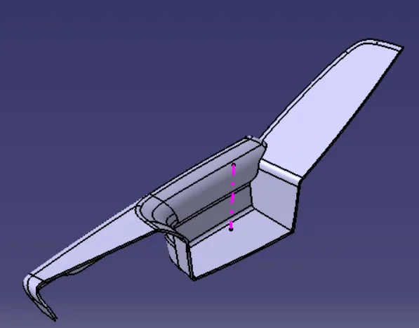
- Creation Of Closed Body
- Closed surface command is performed with the help of part workbench and later the draft analysis is performed
Part -04 : Bottle Holder
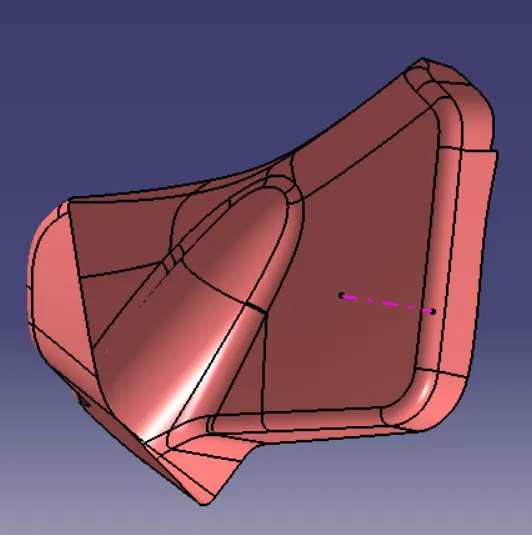
1. Creating the tooling axis : for bottle holder by create a point on surfaces respectively to the 0 value. It automatically create at mid surface and generate the line to the direction of y axis. Check the draft analysis. After checking some of the areas will not be clearing. So we can rotate and adjust the line by checking the handle so that we can find the exact axis.
.
2.Creation Of Class B Surface
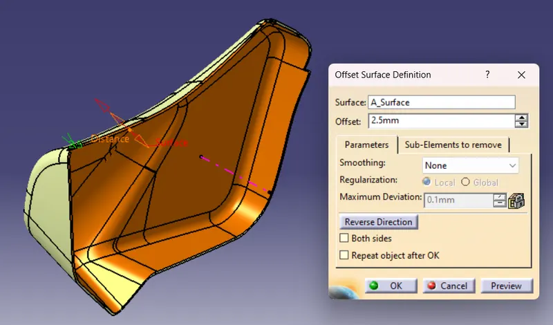
- Now, Class B surface has to be created. For this, multiple extract is used to extract surface in a single operation. Surfaces obtained are the offset for 2.5mm.
- The Unfilled areas have to be offset separately and needs to be filled with multisection and other surface joining commands and join them together.
- Check the B surface by boundary command to make sure there is no gap in the surface.
3.Creation Of Class C Surface
- Now class C surface has to be created and it is created from the boundaries obtained from the Class A surface. This boundary is provided as the input curve for sweep command. Using sweep command, class C surface is created.
- Appropriate sweep is the provided considering the flash and considering manufacturing procedures. Surfaces are extrapolated if necessary.
4. Creation Of Closed Body
- Closed surface command is performed with the help of part workbench and later the draft analysis is performed.
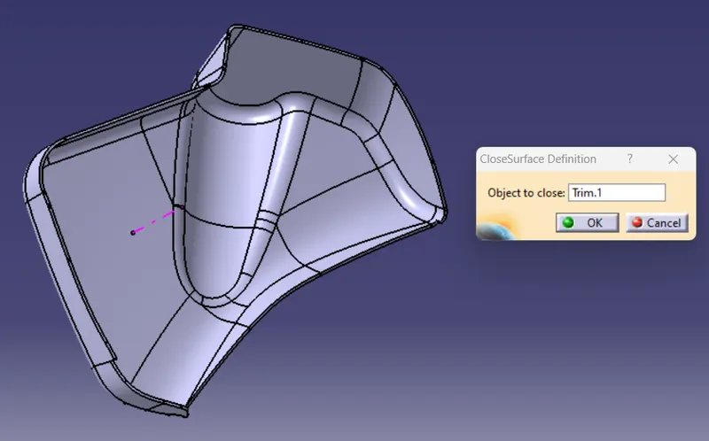
5. Draft Analysis Of Closed Body
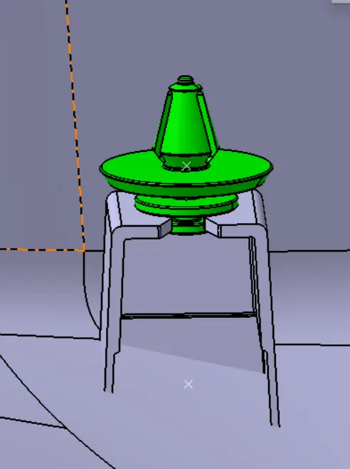
Push pin with Dog house for Lower substrate – Door panel attachment
Steps Followed:
1. Create a point and axis system on the surface wherever needed.
2. Sketch and pad a block. Give drafts and fillets and cutout for the placement of push pin.
3. Give coreout as per dimensions.
4. Copy the features to wherever needed by copying the feature and geometrical sets and replace the points.
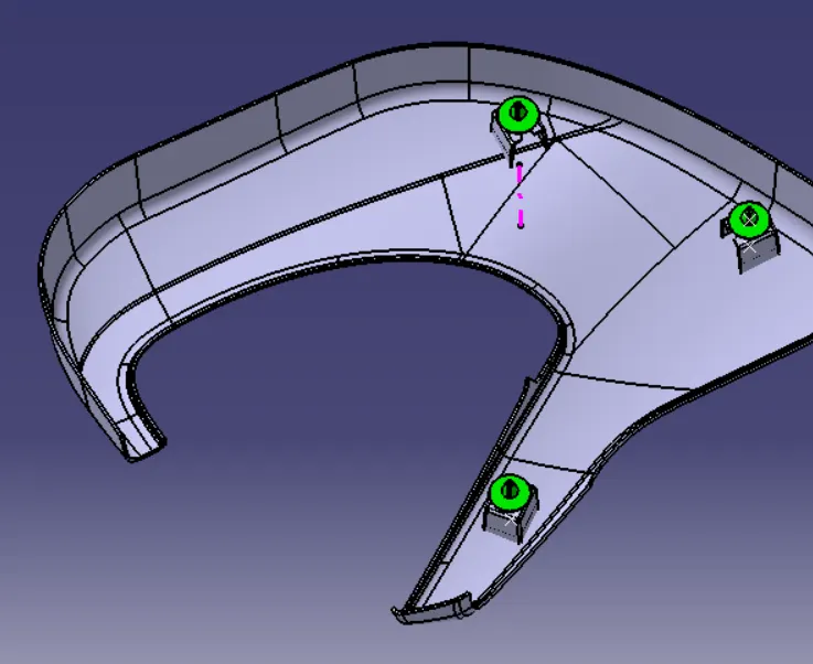
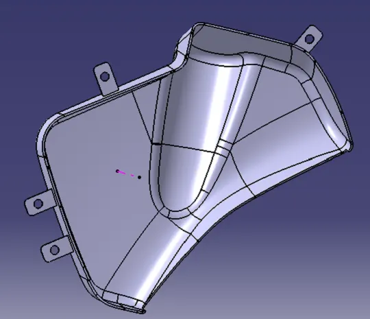
Flange with a hole for the heat stakes in Bottle Holder to attach with Lower Substrate
Steps Followed:
1. Create a point and plane on the curve wherever needed.
2. Sketch and pad a block. Give drafts and fillets and cutout for the placement of heat stakes.
3. union trim with the main body.
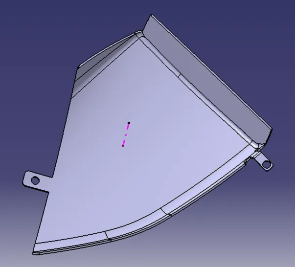
Flange with a hole for the heat stakes in Map Pocket to attach with Lower Substrate
Steps Followed:
1. Create a point and plane on the curve wherever needed.
2. Sketch and pad a block. Give drafts and fillets and cutout for the placement of heat stakes.
3. union trim with the main body.
Assembly Images.