Week 12- Final project
Week 12- Final project: Development of a Door Trim panel
INTENT :
To develop the Door Trim panel
OBJECTIVE:
- Creation of CAD model considering the following inputs as like in OEM and tier1 companies
- a) Class A surface
- b) Nominal thickness: Refer to master sections
- c) Attachment strategy :
- Find an attachment strategy for the door panel complete work.
- Use Push pin with Dog house for Lower substrate – Door panel attachment
- Use heat stakes for part-to-part attachment
Output required:
- Create thickened part using the master section for reference
- Create the mounting features as per design guidelines in the industry and with master sections
- Apply Material details
- Draft analysis & Tooling analysis
- Creation of parting lines and checking tooling feasibility
SOFTWARE USED: CATIA
Let us look at how we have designed
The door trim panel is the creation of a CAD model considering the following inputs as in OEM and tier1 companies
Class A surface is given but after applying boundaries check, it has been found there is some improvement needed to be actioned to get a closed surface. Nominal thickness is taken from the provided master sections Based on the knowledge that has been gained by taking the Plastic Design Course by CATIA V5 I have developed Class B Surgaces, Class C Surfaces, and tooling axis for every single part, also, I found a strategy to assemble the four separate parts into one part design by creating engineering features such as Heat Stakes, Ribs, Dog Houses and Flanges.
1- Armrest Part:
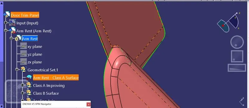
a. Class A Improvement:
First I have found that Class A that been given has open boundaries
Class A Improved:
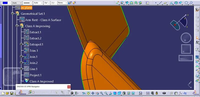
Class B is created by offsetting Improved Class A by 2.5 mm as per the master section.
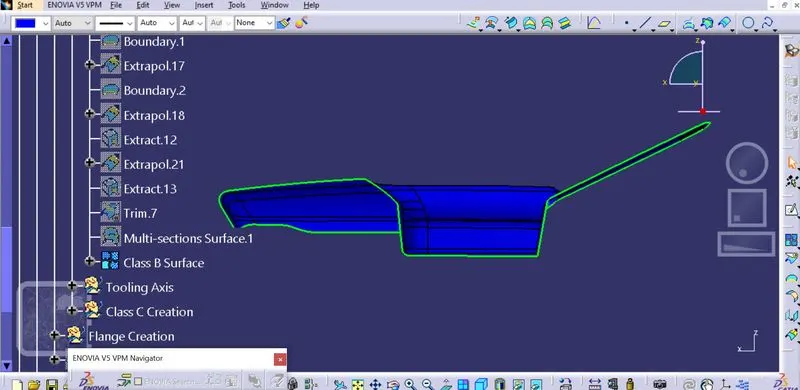
Class C is created by sweeping Improved Class A Surface and it has been trimed with Class B Surface.
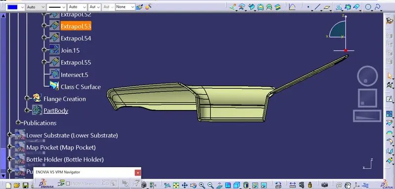
Main Tooling Axis and Side Tooling Axis are created in such a way as to provide drafting.
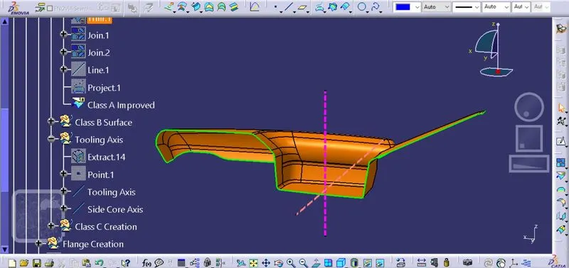
Close Body is created from the fully closed surface:
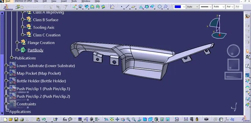
Applied material details as a wooden Alpine Fir for the armrest body.
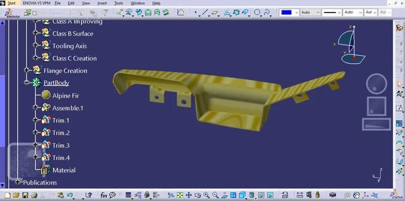
In order to Join the Armrest body with the other bodies, I created 4 Flanges separately with counter holes, Flanges are different based on the engineering features that will be held. Then these flanges are assembled to the main body (Armrest) by interim feature.
Each Flange was created by extracting the surface from Class C Surface added by Generative Surface. then I applied a close surface feature to create the flange body, Drafted by 0.5 deg, and Filleted. Also, it is important to mention that the counter holes were created by iso-constrained, positioned sketches, and then padded it and drafted before it was removed from the main flange.
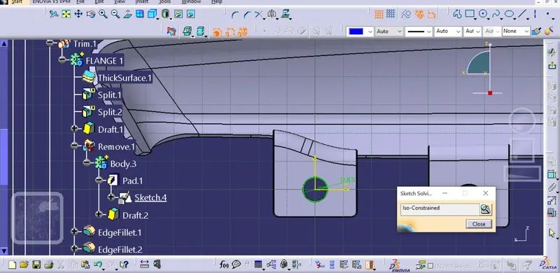
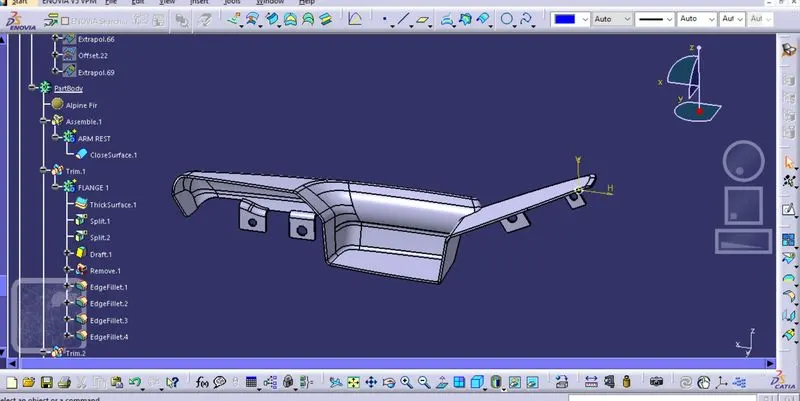
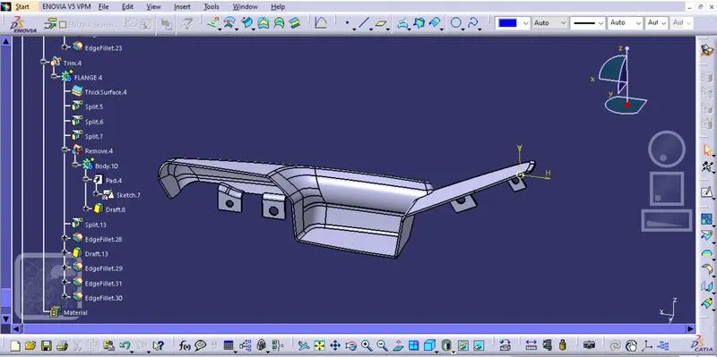
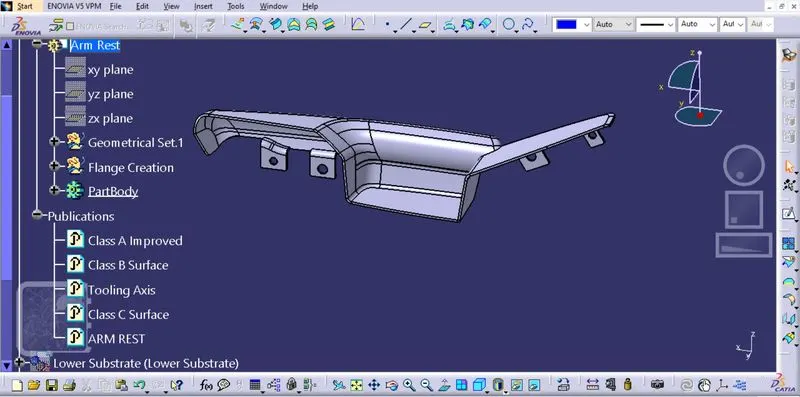
Proper Sketch Tree for Arm Rest Body:
Publications:
Drafting Analysis:
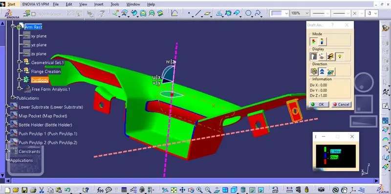
By applying drafting analysis at 2.9 Deg, we can see most bodies are been cleared. As Green is set at 2.9 degrees, blues is Zero, and less than Zero it is red colored.
2- Lower Substrate:
A- Class A Surface was given is checked and found out it is perfectly closed boundaries, no further action is to be taken.
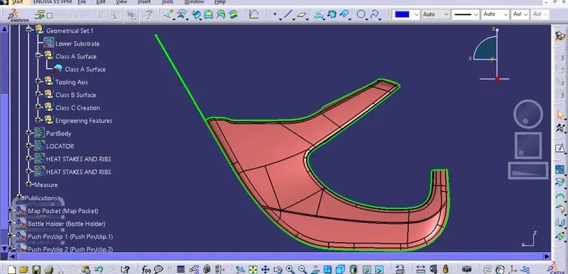
Class B is created by offsetting Improved Class A by 2.5 mm as per the master section.
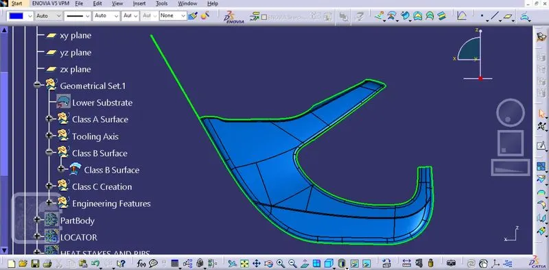
Class C is created by sweeping Improved Class A Surface and it has been trimmed with Class B Surface.
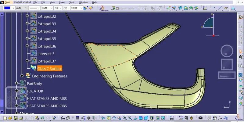
Main Tooling Axis is created in such a way as to provide drafting.
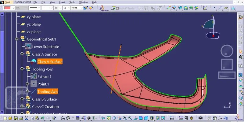
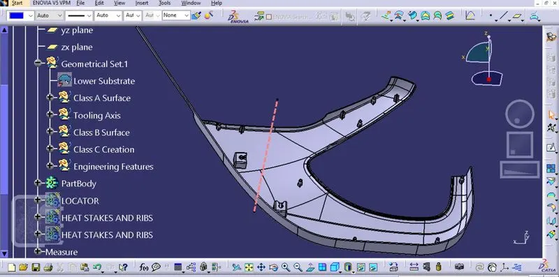
Close Body is created from the fully closed surface:
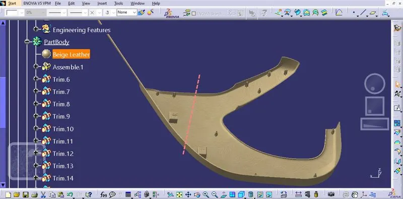
Applied material details as a Baige Leaher for the Lower Substrate.
In order to Join the Lower Substrate with the other bodies, I will be using the Lower Substrate as the main body where others can be installed according to it. All connecting engineering features are created and attached to this body while flanges will be connecting this main body to other bodies. two dog houses are created, 8 heat stakes, and 2 4 way lockers are created and attached to this body.
Each engineering feature was created by extracting surface from Class C Surface added by Generative Surface. then I applied a close surface feature to create the flange body, Drafted by 0.5 deg, Filleted, and champ here. Also, it is important to mention that features were created by iso-constrained, positioned sketches and then padded and drafted.
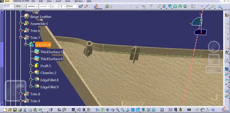
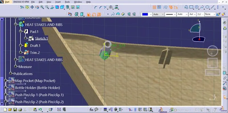
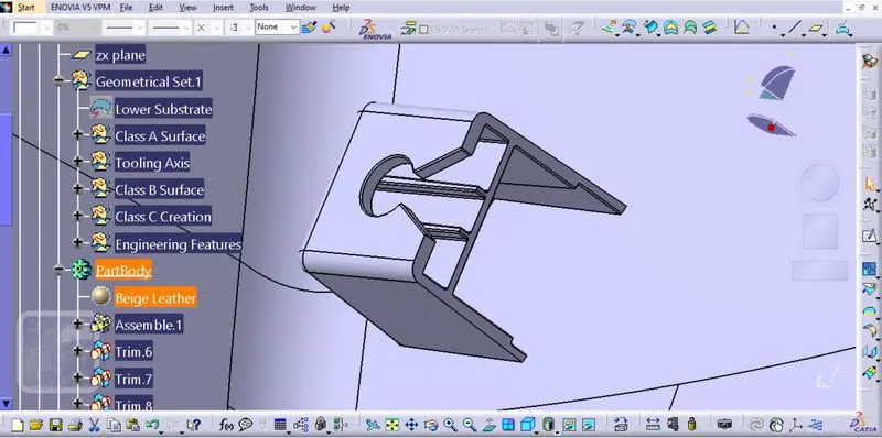
Proper Sketch Tree for Lower Substrate Body:
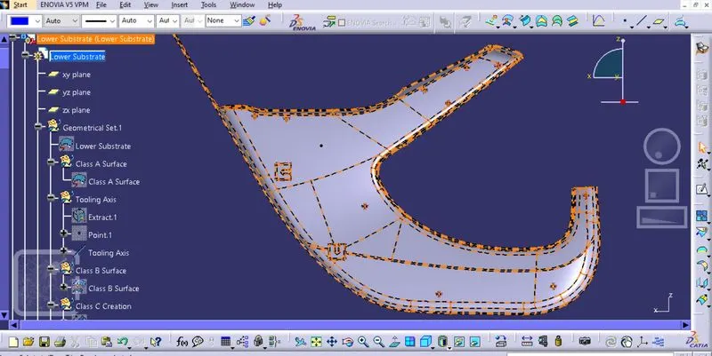
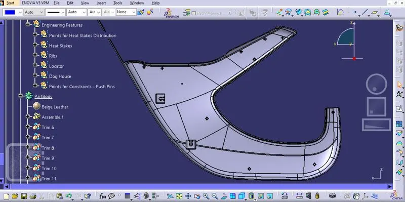
Publications:
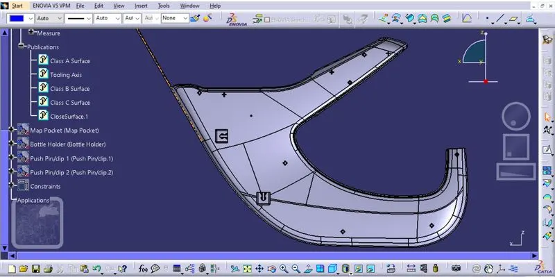
Drafting Analysis:
By applying drafting analysis at 2.9 Deg, we can see most bodies are been cleared. As Green is set at 2.9 degrees, blues is Zero, and less than Zero it is red colored.
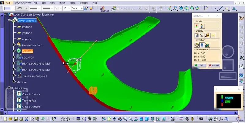
For the engineering features the draft angel is chosen as 0.5 deg as per below:
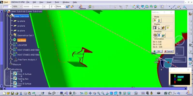
3- Map Pocket:
A- Class A Surface was given is checked and found out it is perfectly closed boundaries, no further action to be taken.
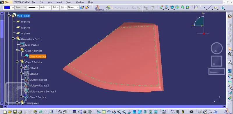
Class B is created by offsetting Improved Class A by 2.5 mm as per the master section.
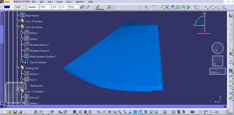
Class C is created by sweeping Improved Class A Surface and it has been trimmed with Class B Surface.
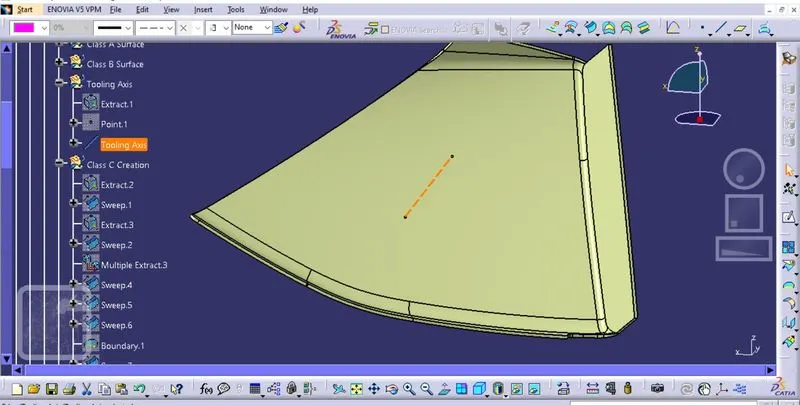
Main Tooling Axis is created in such a way as to provide drafting.
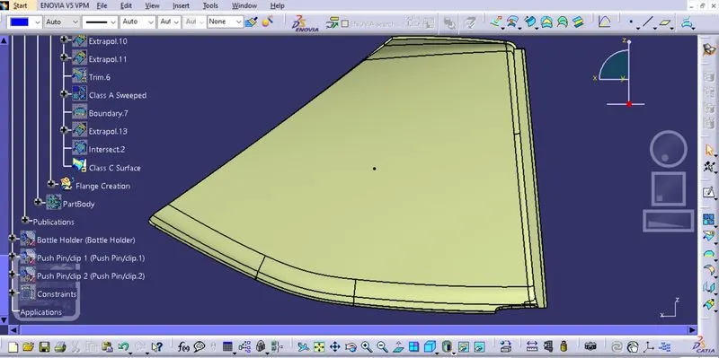
Close Body is created from the fully closed surface:
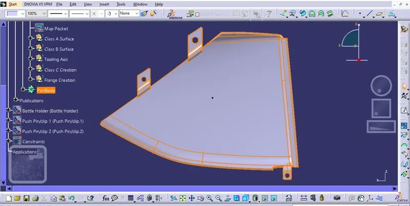
Applied material details as a plastic for the body.
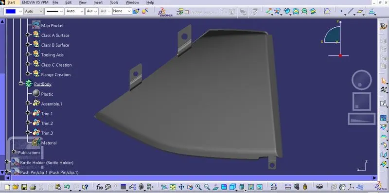
In order to Join the Map Pocket with the other bodies, I created 3 Flanges separately with counter holes, Flanges are different based on the engineering features that will be held. Then these flanges are assembled to the main body (Map Pocket) by interim feature.
Each Flange was created by extracting the surface from Class C Surface added by Generative Surface. then I applied a close surface feature to create the flange body, Drafted by 0.5 deg, and Filleted. Also, it is important to mention that the counter holes were created by iso-constrained, positioned sketches and then padded and drafted before it was removed from the main flange.
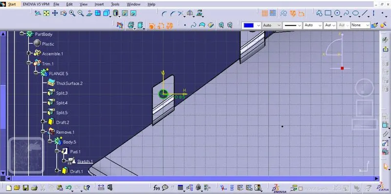
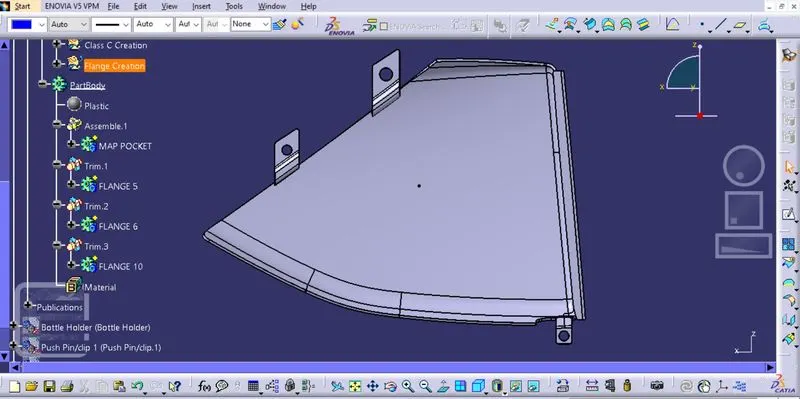
Publications:
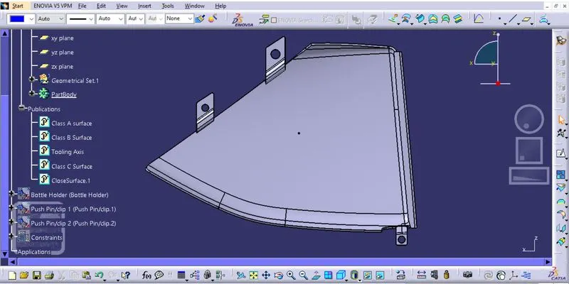
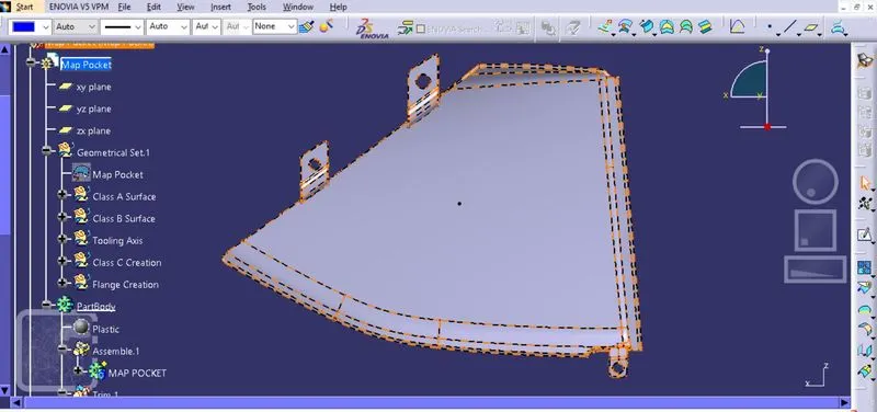
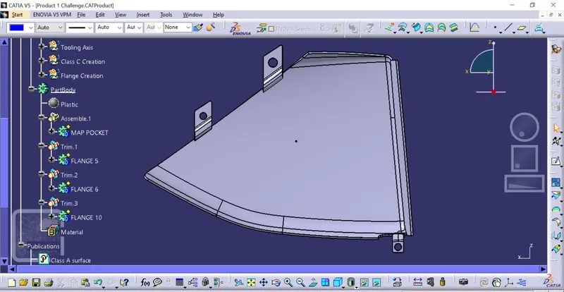
Proper Structural Tree:
Drafting Analysis:
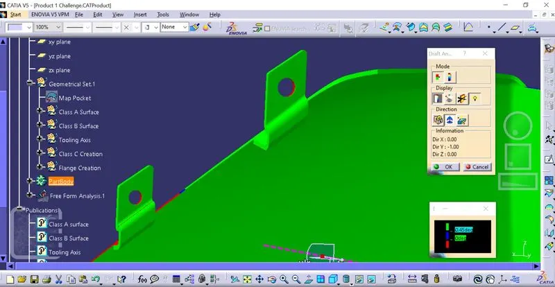
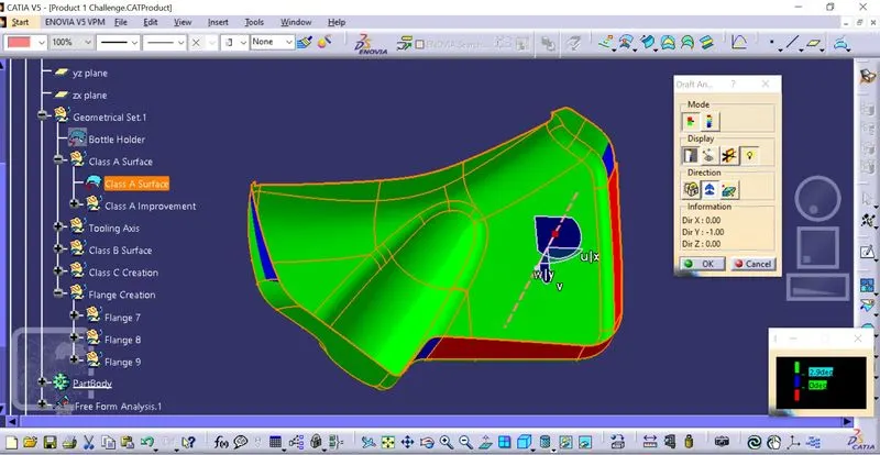
By applying drafting analysis at 2.9 Deg, we can see most bodies are been cleared. As Green is set at 2.9 degrees, blues is Zero, and less than Zero it is red colored.
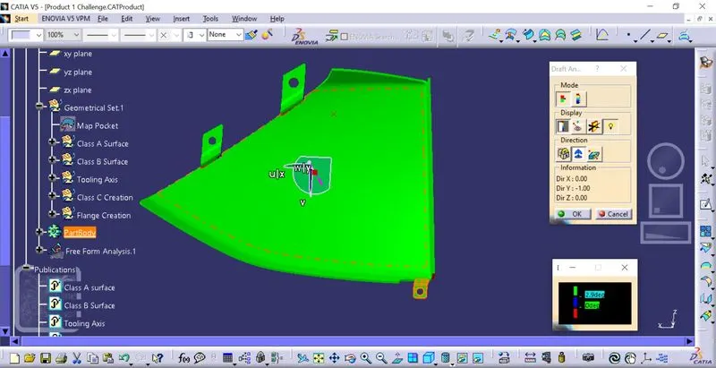
For the Flanges is set at 0.45 it is drafted to 0.5 Deg.
4- Bottle Holder:
Class A Improved:
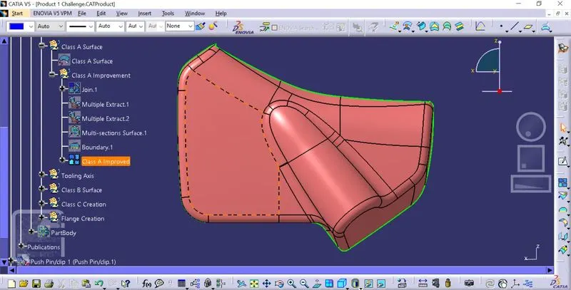
Class B is created by offsetting Improved Class A by 2.5 mm as per the master section.
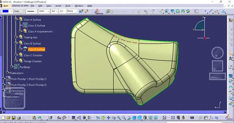
Class C is created by sweeping Improved Class A Surface and it has been trimmed with Class B Surface.
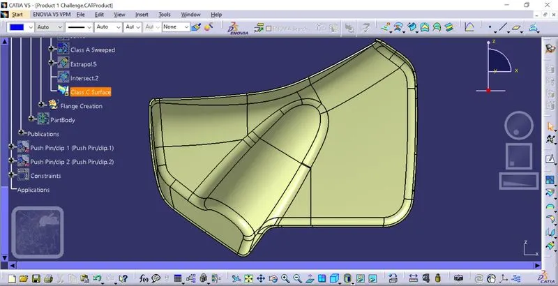
Main Tooling Axis and Side Tooling Axis are created in such a way as to provide drafting.
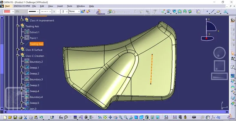
Close Body is created from the fully closed surface:
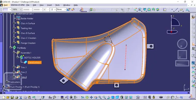
Applied material details as a plastic for the body.

In order to Join the Bottle Holder with the other bodies, I created 3 Flanges separately with counter holes, Flanges are different based on the engineering features that will be held. Then these flanges are assembled to the main body (Bottle Holder) by interim feature.
Each Flange was created by extracting the surface from Class C Surface added by Generative Surface. then I applied a close surface feature to create the flange body, Drafted by 0.5 deg, Filleted. Also, it is important to mention that the counter holes were created by iso-constrained, positioned sketches and then padded and drafted before it was removed from the main flange.
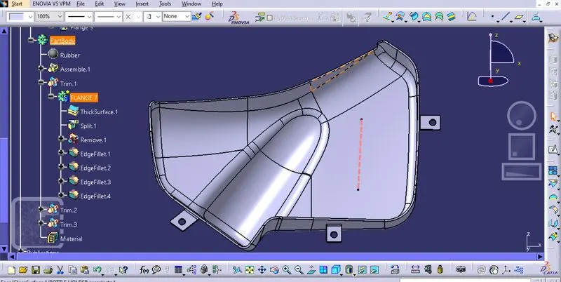
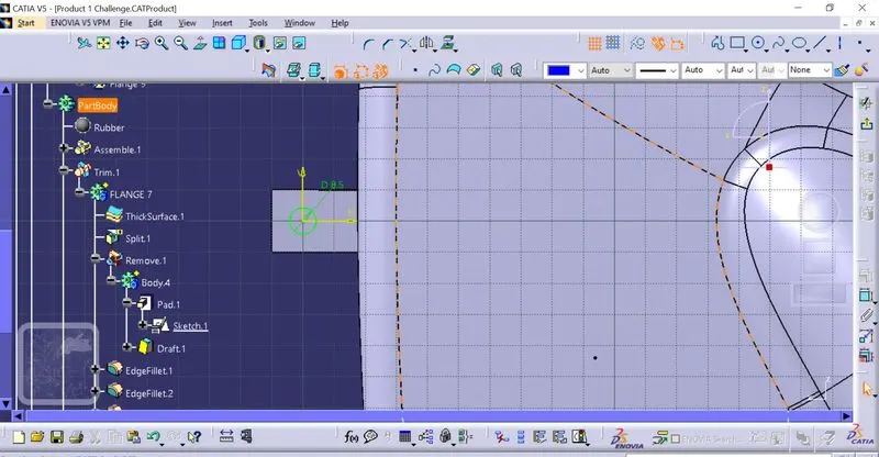
Publications:

Proper Structural Tree:
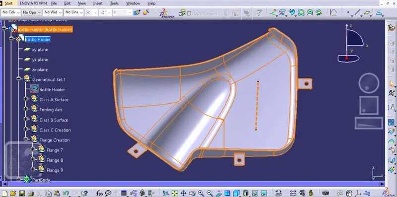

Drafting Analysis:
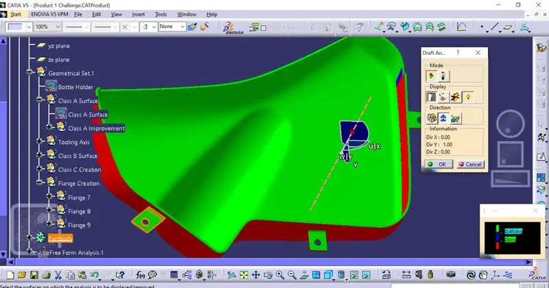
By applying drafting analysis at 2.9 Deg, we can see most bodies are been cleared. As Green is set at 2.9 degrees, blues is Zero, and less than Zero it is red colored. As it is shown in the next image that in Class A Surface there are some patches cannot be cleared by a draft angle of 3 Deg. it is suggested to be reported back to the drafter in real life but as this is a study project, ill be ignoring this.
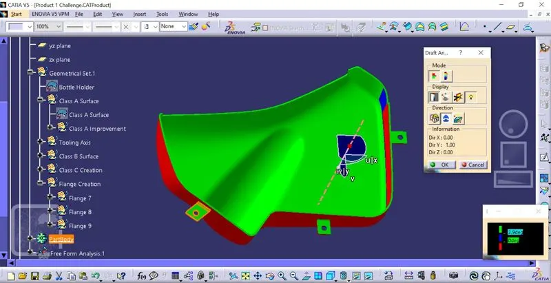
and it is set t be 0.5 del draft angle for the flanges:
Push Pin:
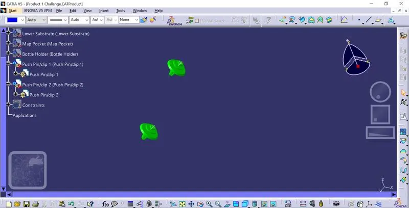
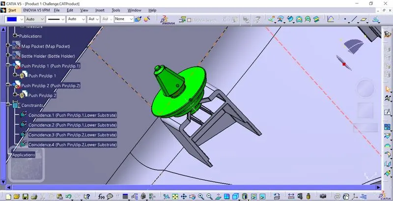
As I have created two Dog Houses for this part assembly, I need to import two Push pins.
Both are assembled correctly as shown: