Week 8 - Challenge 2 - Switch Bezel Design
AIM : TO CREATE THE SWITCH BEZEL PLASTIC COMPONENT THROUGH GIVEN CLASS A SURFACE
INTENT:
- To create class B & class C surface for the given component
- And To form the tooling axis and capture the surface properly
- Finally To check the feasibility of the component with a draft of 3 degrees
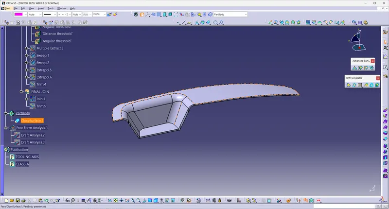
GIVEN CLASS A SURFACE :
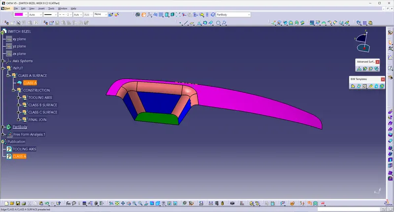
Tooling axis creation
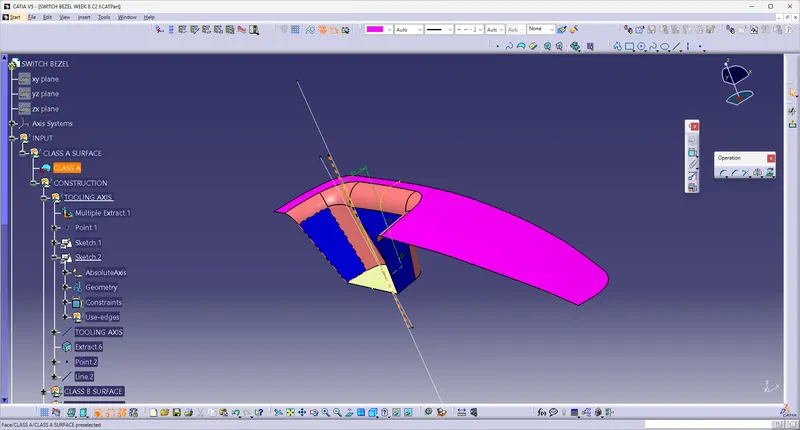
The tooling axis is the direction of drawing a sheet metal where the finished component is easily ejected on a particular direction and axis. The tooling axis is important for removing the material when finished the tooling axis is created from the given class A surface
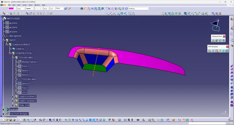
Creation of tooling axis Bisecting method
Extract the base surface of the given Class- A Surface and create the center point of the Extracted surface and then create two sketches on two planes by taking the cross section of the given surface in the particular plane
Then create two sketches on two planes by taking the cross section of the given surface in the particular plane
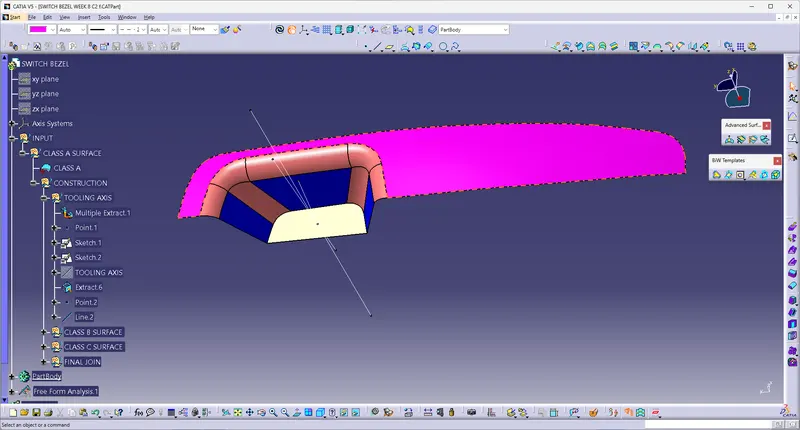
tooling axis created from the two lines using the cross section and also creating one with the help of cross section line of the surface on X plane as bisecting line And now by creating another bisecting line using those two plane sketches is the tooling axis for this particular Class - A surface
As the 4th wall is not there, an assumption is made and the axis is taken which is 6 degrees from the horizontal axis.
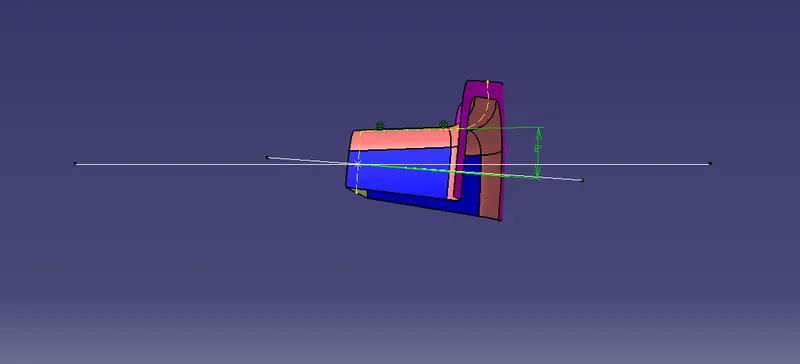
Using the two side walls 1st axis is made
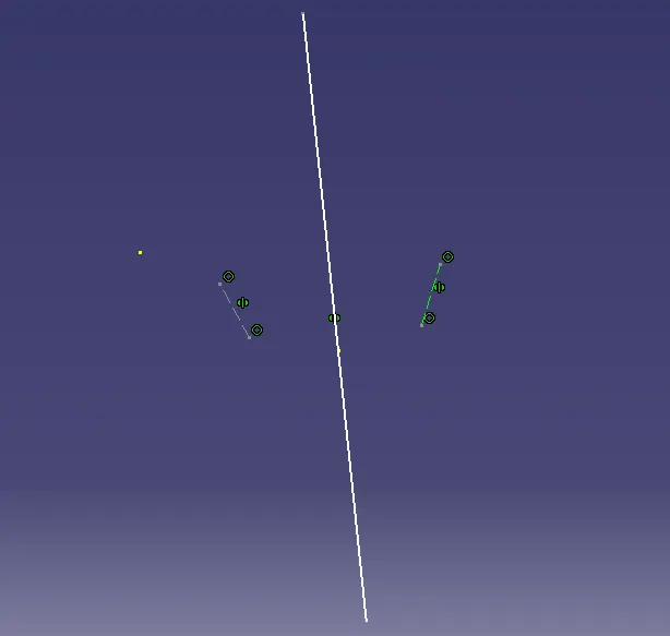
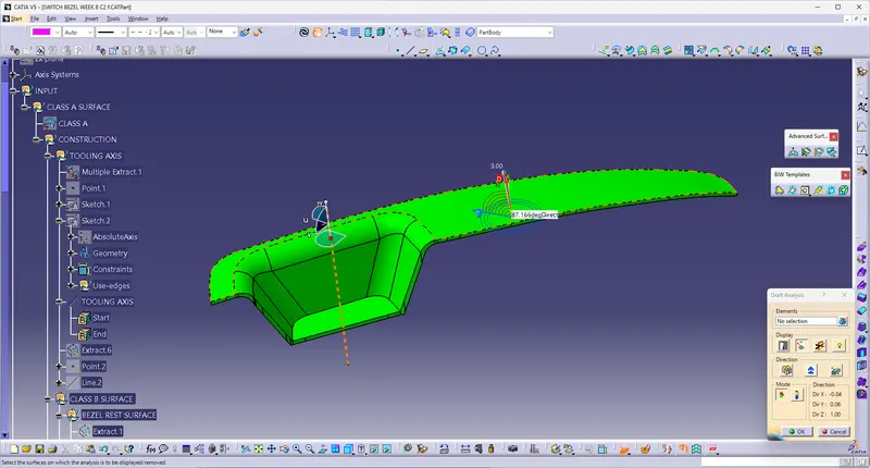
Draft Analysis
When a plastic component is made, we can observe that there is a draft angle given on each side from the base which is lesser than 90 degrees. This is because in the criteria of making a plastic material the mold should release the material when finished. if the mold surfaces are 90 degrees the material won't release from the mold because of friction due to contraction of material when cooled
To resolve this problem we CAD engineers maintain a standard rule to design the plastic mold or die's in such a way that there is no problem while ejecting the plastic component. So a minimum of 3 - 10 degrees of draft angle is given to every plastic component while designing
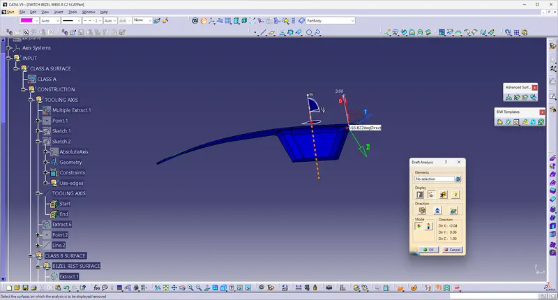
From the below image it can be seen that one wall of the part fails in the feasibility check this happened due to the draft angle which is given to the axis at the beginning. To avoid this, again the angle has to be increased and update has to be done
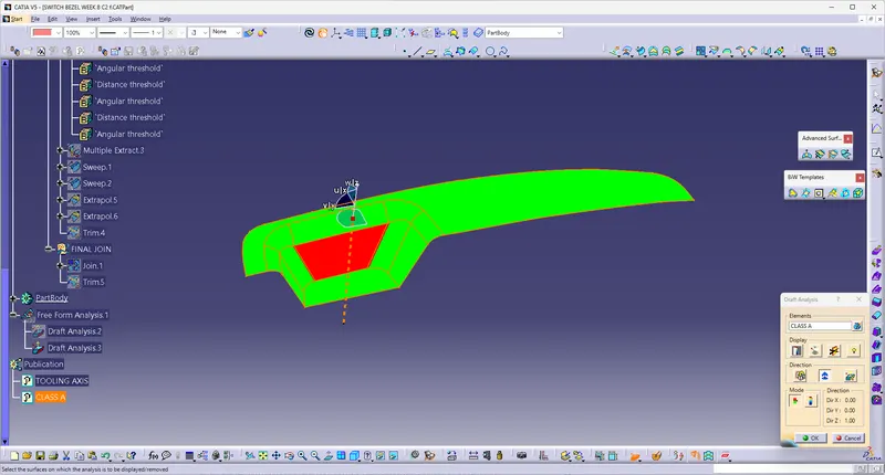
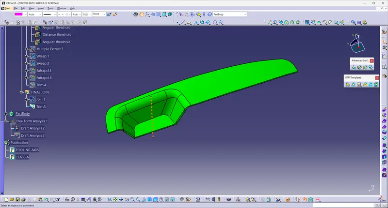
After increasing the angle it can be seen that there is no draft failure and now the component is feasible and can be manufacturedDraft analysis is performed on the given Class-A surface, and it is clearly observable that there is no negative draft on the surface.
Creation of Class - B surface
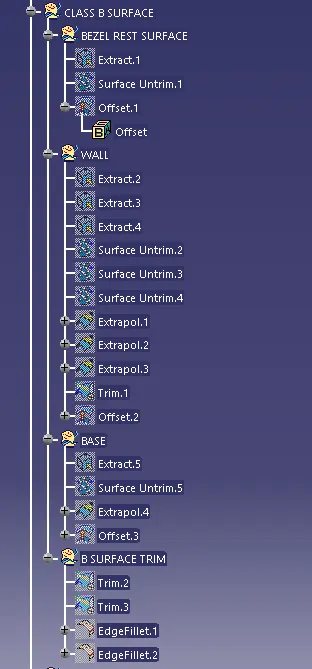
To start with, the top rest surface is extracted and untrimmed and extrapolated, so that this can be used to trim with other surface to form the class B surface Likewise other surfaces are also taken, untrimmed and extracted to trim with the adjoint surfaces
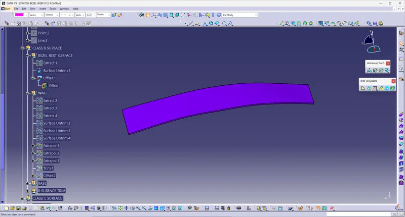
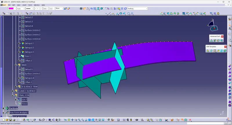
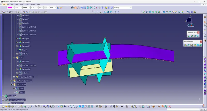
extracting the class - A surface without the fillets and then untriming and extrapolateing them to join them, and after that offset the surface to 2.5 mm thickness which forms as the Class - B surface and then filleting it to 12mm Once all the adjacent surfaces are taken, they are trimmed and form into the bezel surface
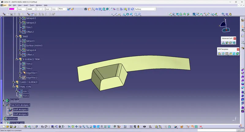
As per the requirement, the fillets are given. In order to given the fillets it is not exactly equal to class A. Along with the fillet radius, part thickness has to be added
Creation of Class - C surface
By extracting the boundary of the class - A surface, the surface required for the class - C is obtained
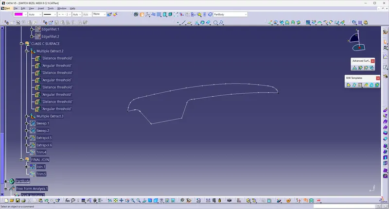
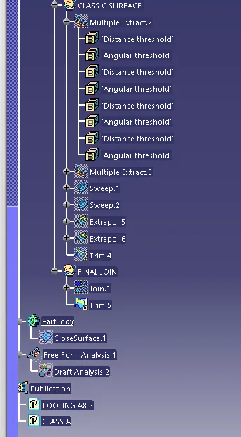
To capture class C surface it is necessary to sweep it to the required length. However for this as the border formed is having number of small sections the border curve can be smoothened and then swept or else done in parts
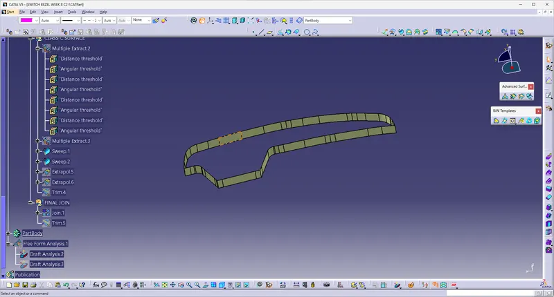
After forming the class b & C all the three surfaces can be trimmed and check for any discontinuity
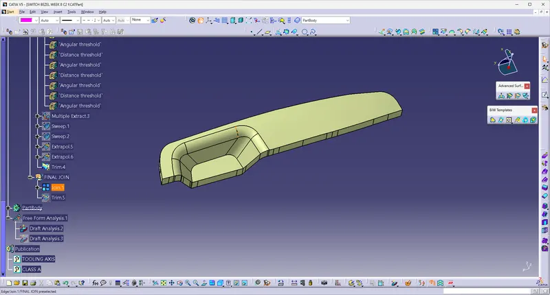
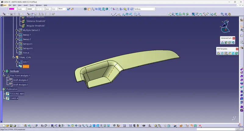
After trimming, this is how the surface will look like
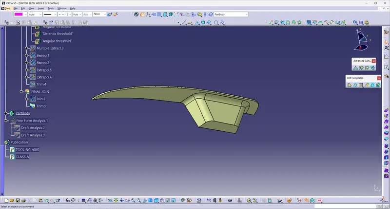
This is the Solid formed after the class A, B & C surface
various view of thr draft angle
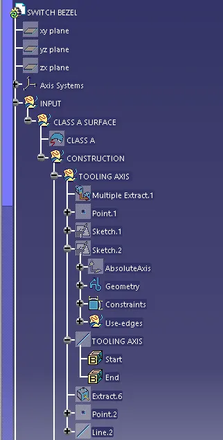
Tree structure