Week 12- Final project
DOOR TRIM PANEL
A door trim panel, also known as a door panel or door card, is an interior component of a vehicle's door. It is typically made of molded plastic or other materials and is designed to cover the metal framework of the door, providing an aesthetically pleasing and functional surface.
The door trim panel serves several purposes:
-
Aesthetics: It enhances the interior appearance of the vehicle by covering the inner workings of the door, including the door handle, window mechanism, and wiring.
-
Protection: It helps protect the inner components of the door from damage, such as moisture, dust, and debris.
-
Comfort: The door trim panel often includes padding or insulation materials to reduce noise and vibration, making the interior cabin quieter and more comfortable.
-
Functionality: It may house various controls and features, such as power window switches, door lock controls, mirror adjustments, and speaker systems.
The door trim panel is typically attached to the door frame using a combination of clips, screws, and adhesive.
It can be removed for maintenance or repair purposes, such as fixing window regulators, replacing speakers, or accessing the wiring harness.
However, the process of removing and reinstalling the door trim panel can vary depending on the vehicle make and model.
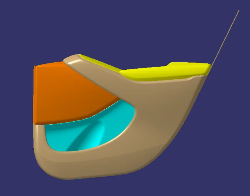
GIVEN INPUTS
Creation of CAD model considering following inputs as like in OEM and tier1 companies
- a) Class A surface
- b) Nominal thickness : Refer master sections
- c) Attachment strategy :
- Find a attachment strategy for the door panel complete work.
- Use Push pin with Dog house for Lower substrate – Door panel attachment
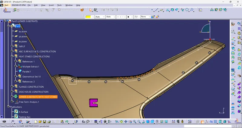
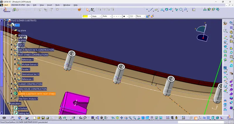
- Use heat stakes for part to part attachment
CLASS A SURFACE
In automotive industry, a class A surface is any of a set of freedom surfaces of high efficiency and quality.
Although, strictly, it is nothing more than saying the surfaces have curvature and tangency alignment – to ideal aesthetical reflection quality, many people interpret class A surfaces to have G2 (or even G3) curvature continuity to one another.
Class A surfacing is done using computer-aided industrial design applications.
Class A surface modellers are also called "digital sculptors" in the industry.
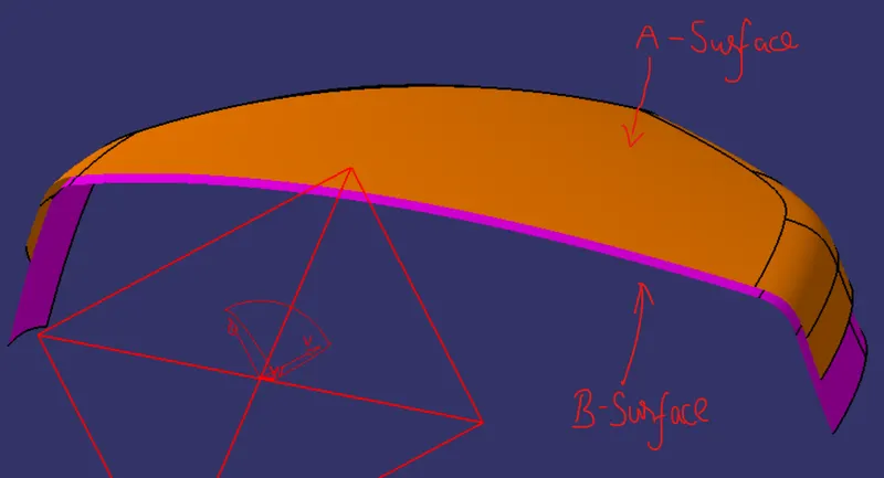
Industrial develop their design styling through the A-Surface, the physical surface the end user can feel, touch, see etc.
Below are the CAD platforms where we can create class-A surfaces:
1] Autodesk Alias
2] ICEM Surf
3] FreeStyle Module in CATIA by Dassault Systems
4] Imageware and Unigraphics Class A module
CLASS B SURFACE
B surface is the offset of Class A surface i.e, thickness of a part it is not visible it is inside part.
Ribs, Locators, Screw bosses, Heat stakes, Dog houses, etc, are loacted in the B surface.
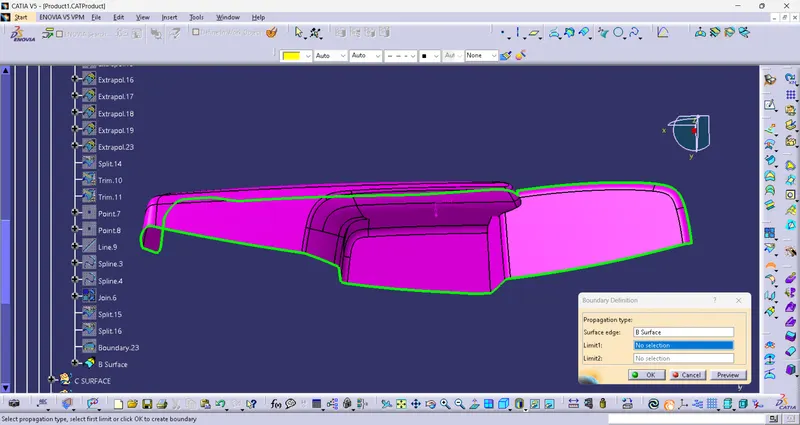
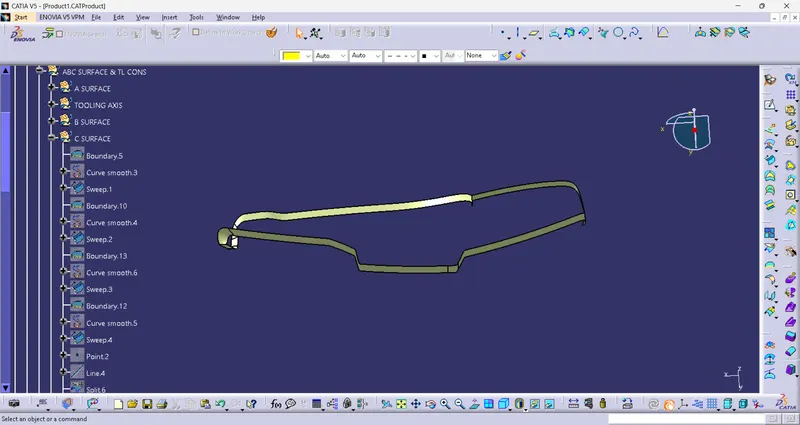
CLASS C SURFACE
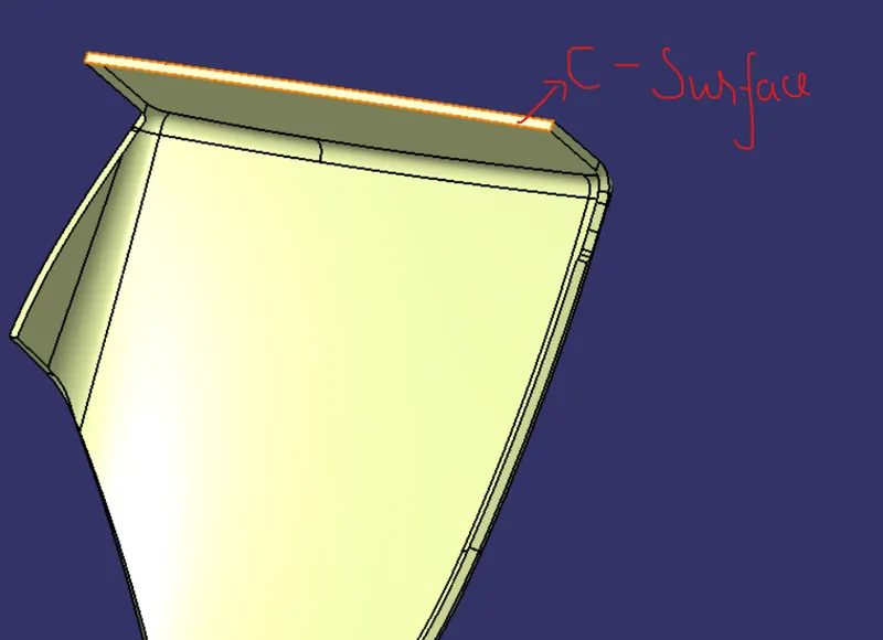
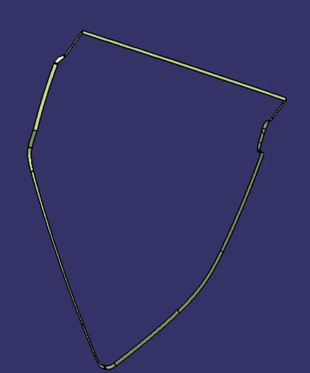
The surface to join the class A surface and class B surface is called Class C surface.
It may be drafted to some degress(0.5deg-3deg) or normal with the reference A surface with respect to the tooling axis.
TOOLING AXIS
Tooling axis was created to perform draft analysis where the core and cavity opens smoothly.
Tooling axis was normal to core and cavity of the mold.
Tooling axis was created by bisecting method, normal to the surface, to the direction of the compass, etc, of the part.
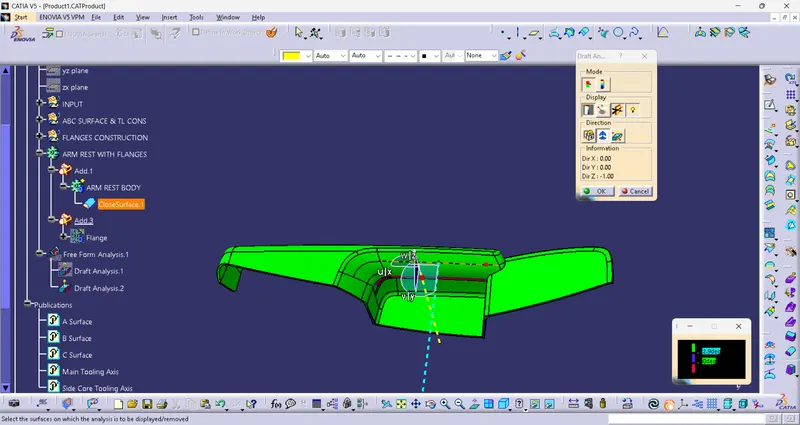
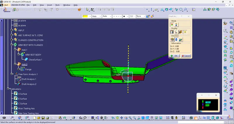
DRAFT ANALYSIS
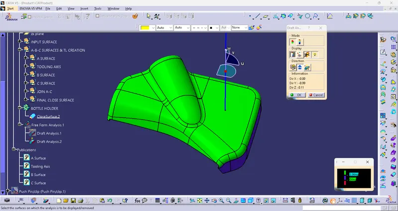
The Draft Analysis command enables you to detect if the part you drafted will be easily removed. This type of analysis is performed based on colour ranges identifying zones on the analyzed element where the deviation from the draft direction at any point, corresponds to specified values.
Tooling direction is the main consideration for plastic part and mould parts because it defines the movement of the mould part and the possibility of the plastic part coming out from the mould part (Core and Cavity)
The finished part is analyzed to detect if the drafted part will be easily removed from the injection molding.
MASTER SECTION
Master Sections are the guides for design requirements which shapes the component after technical styling of Class A Surfaces.
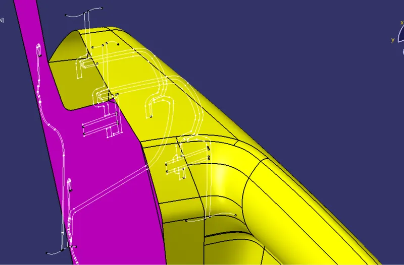
In the master section we find the thickness of the part, flanges and other B side features.
INPUTS
CLASS A SURFACES AND MASTER SECTIONS
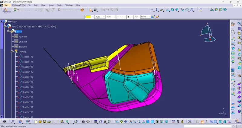
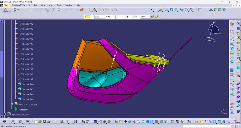
ARM REST
A SURFACE
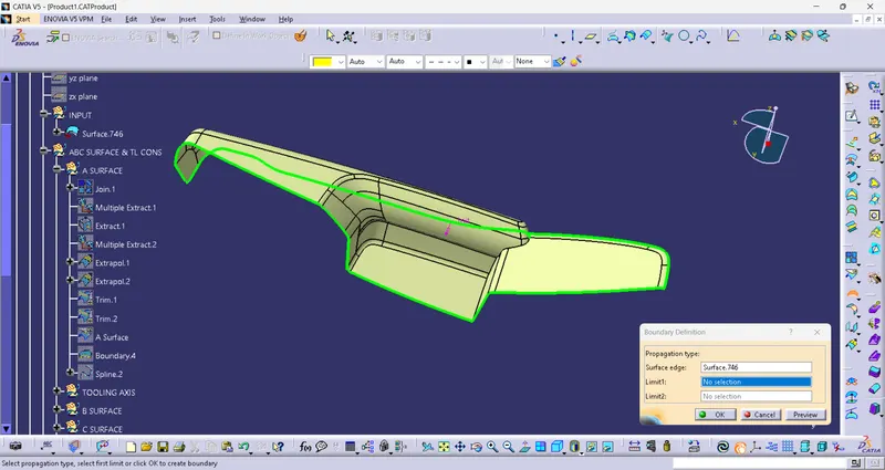
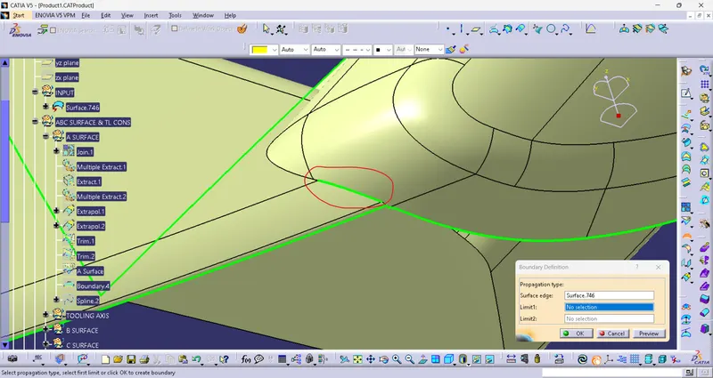
There is a defect in the given class A surface so we have to improve that
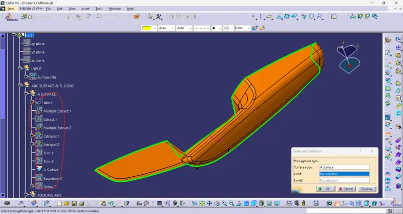
Using those commands finally got a improved class A surface.
TOOLING AXIS
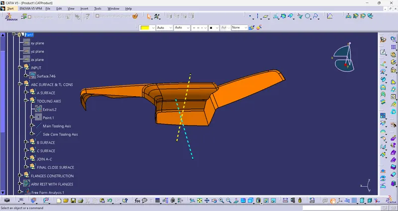
DRAFT ANALYSIS OF A-SURFACE
- With main tooling axis
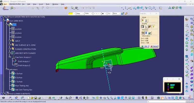
- With side core tooling axis
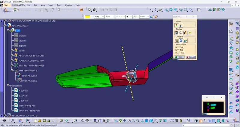
Because of the complicated shape of the part we have to provide two tooling axis (main tooling axis and side core tooling axis).
The part was easily clearing the draft in Z-direction, so the main tooling axis was created by point to direction method.
Also the part was clearing the draft when the side core axis was perpendicular to the main tooling axis
B SURFACE
After offsetting of 2.5mm from the A surface, there is a patches around the surface.
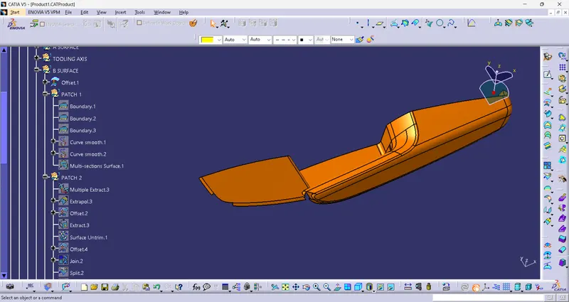
After using various commands and got the B surface
C SURFACE
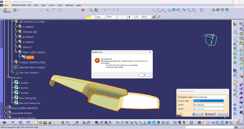
FINAL CLOSE SURFACE
DRAFT ANALYSIS
FULL PART BODY
- With main tooling axis
- With side core tooling axis
ARM REST WITH FLANGES

LOWER SUBSTRATE
A SURFACE
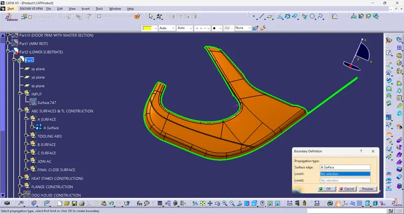
There was no errors in the given class A surface.
TOOLING AXIS
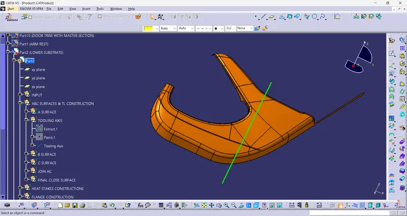
DRAFT ANALYSIS OF A-SURFACE
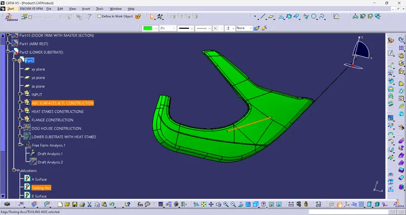
Clearing the draft in Z-direction, so the tooling axis was created by point to direction method.
B SURFACE
Offset of 2.5mm from the A surface.
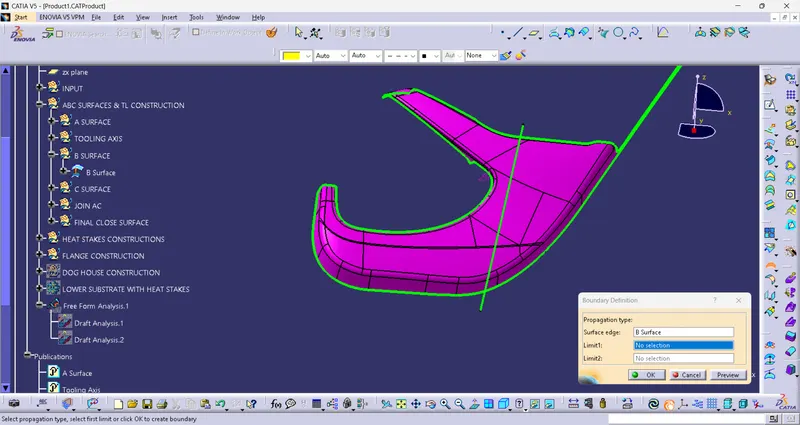
No patches or errors in the offset surface.
C SURFACE
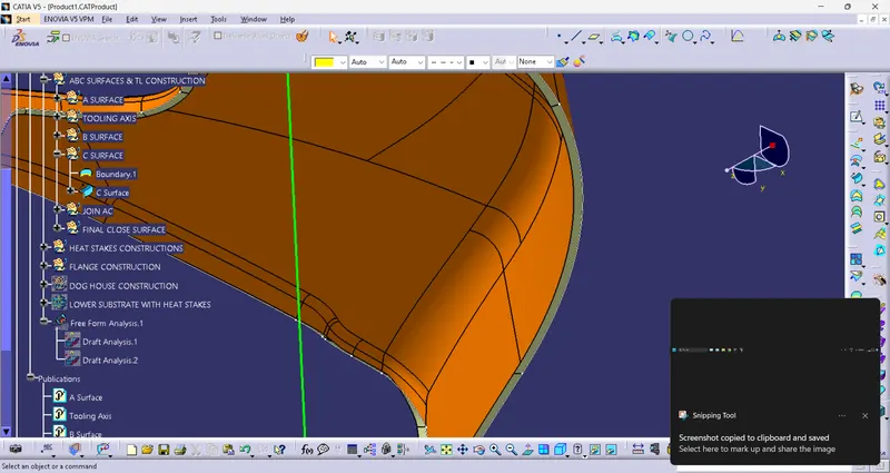
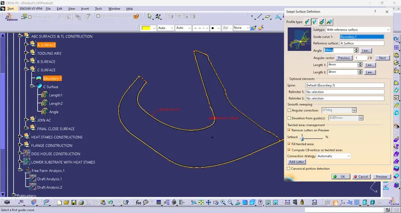
The surface edges of the A surface was parallel to the tooling axis, so the sweep would be 90deg with reference to the A surface.
FINAL CLOSE SURFACE
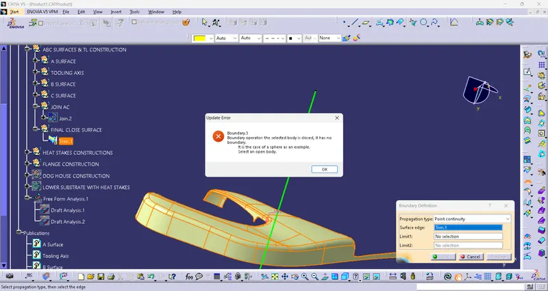
DRAFT ANALYSIS
FULL PART BODY
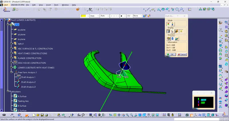
LOWER SUBSTRATE WITH B SIDE FEATURES
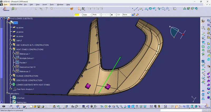
HEAT STAKES
FLANGES
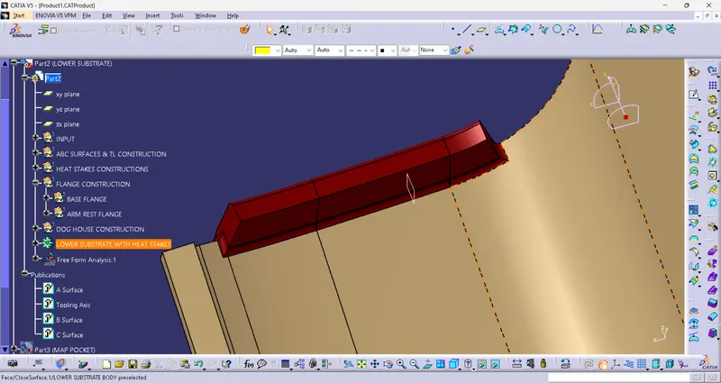
DOG HOUSES
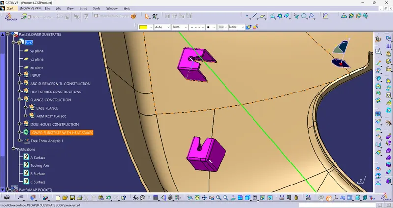
MAP POCKET
A SURFACE
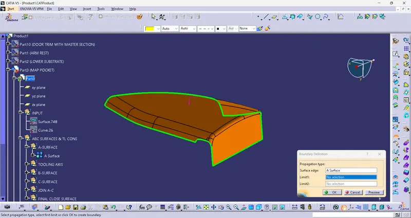
There was no errors in the given class A surface.
TOOLING AXIS
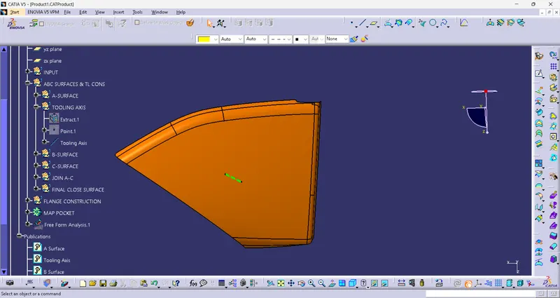
DRAFT ANALYSIS OF A-SURFACE
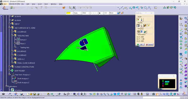
Clearing the draft in Z-direction, so the tooling axis was created by point to direction method.
B SURFACE
Offset of 2.5mm from the A surface.
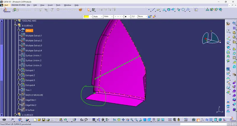
Some missing patches in the offset surface.
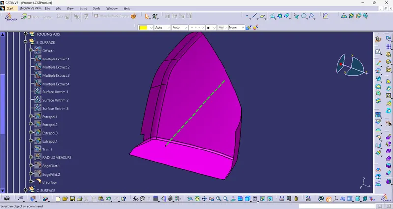
Using various commands like multiple extract, surface untrim, extrapol, trim and edge fillet , got the B surface.
C SURFACE
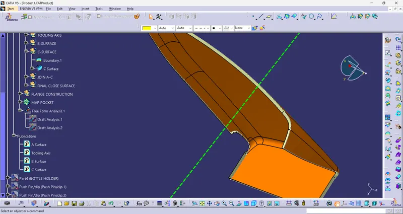
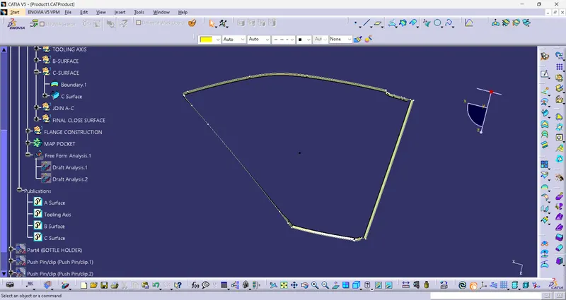
Sweep of 90deg with A surface as a reference, because of parallel surface edges.
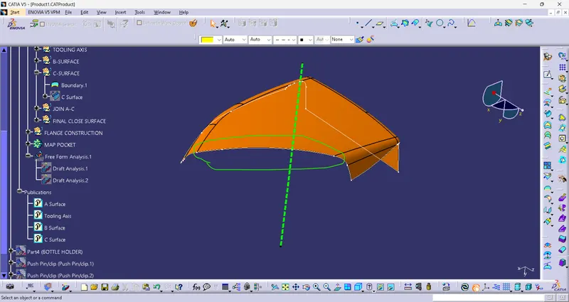
Here the surface edge was perpendicular to the tooling axis, so we have to do, extract the boundary of the edge and then sweep with the draft direction of 3 deg.
FINAL CLOSE SURFACE
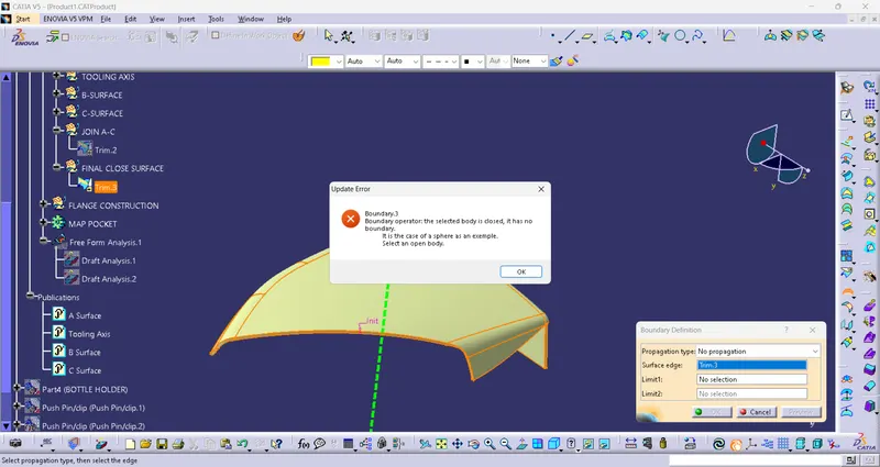
DRAFT ANALYSIS
FULL PART BODY
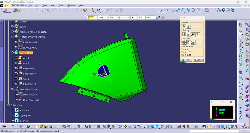
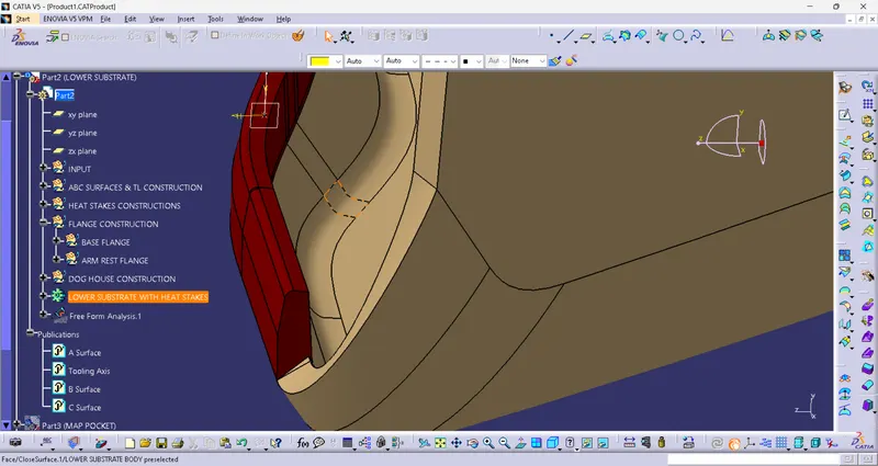
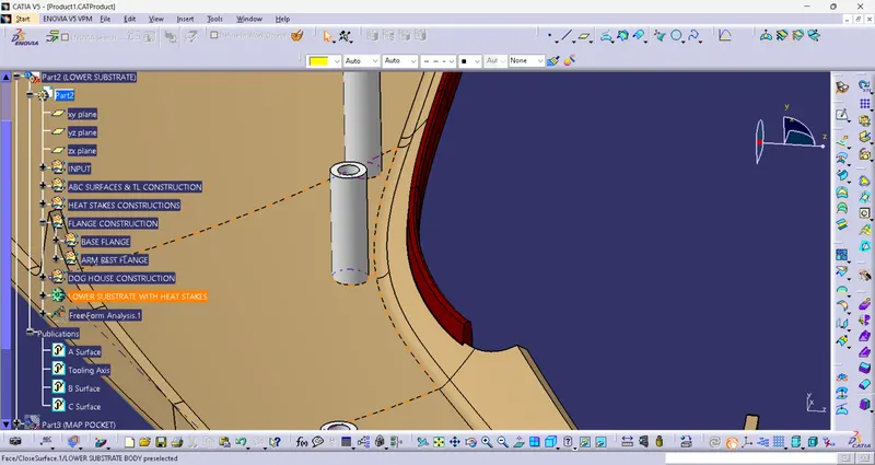
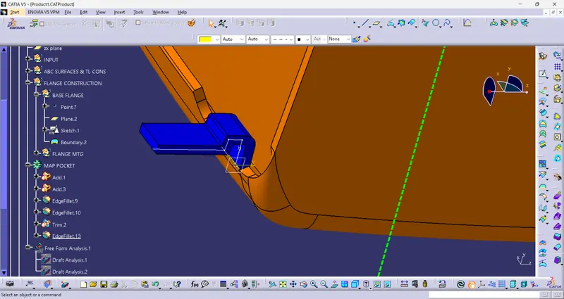
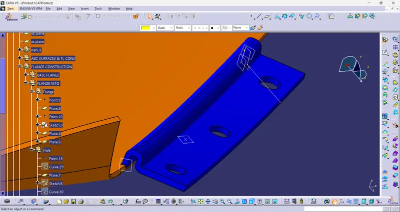
FLANGES
BOTTLE HOLDER
A SURFACE
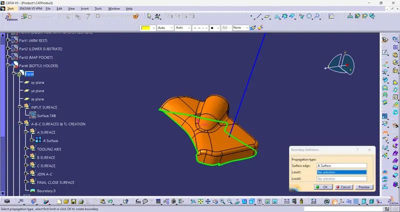
No errors in the given A surface.
TOOLING AXIS
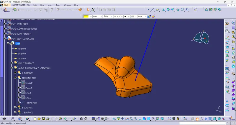
DRAFT ANALYSIS OF A-SURFACE
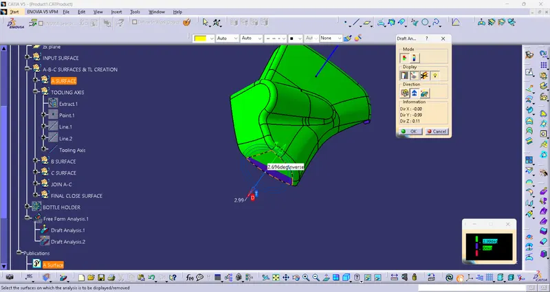
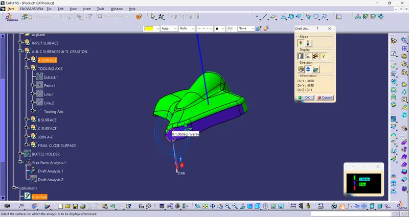
There is no way to clear the draft in point to point method, point to direction method and bisecting method, because the input class A surface was wrong, so initially, we should have to inform class A engineer, or otherway try to improve the surface ourself.
B SURFACE
Offset of 2.5mm from the A surface
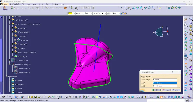
No errors were found on the offset surface.
C SURFACE
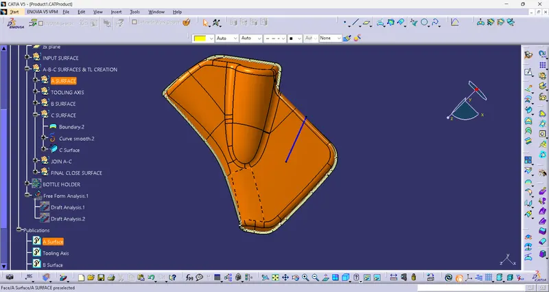
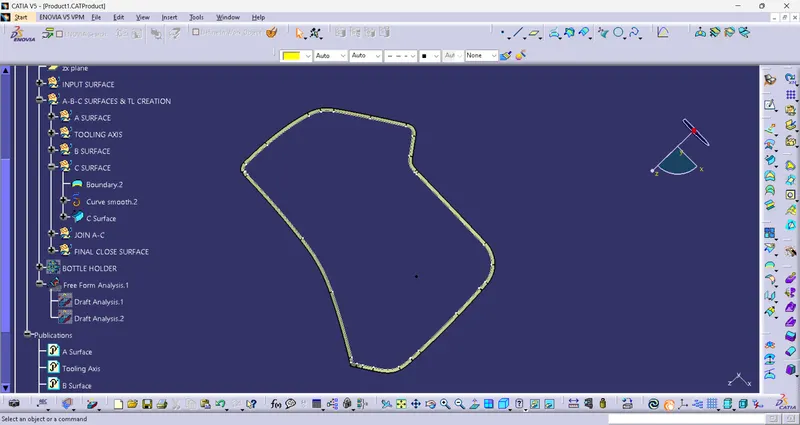
Because of the parallel edges of the A surface with the tooling axis, gone sweep with 90deg reference with the A surface.
FINAL CLOSE SURFACE
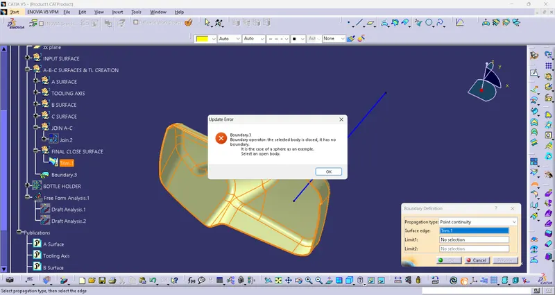
DRAFT ANALYSIS
FULL PART BODY
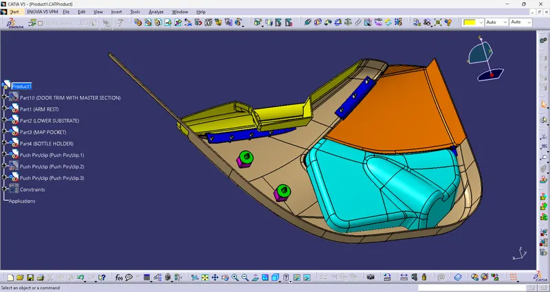
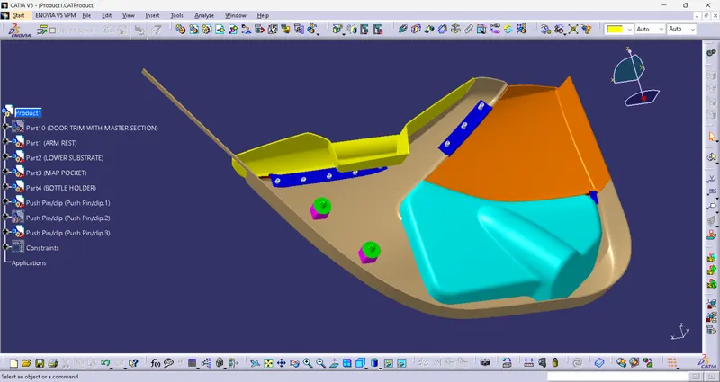
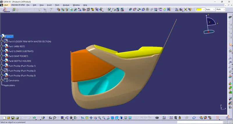
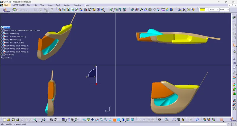
FINAL DOOR TRIM WITH PUSH CLIPS
CONCLUSION:
Finally, the door trim panel was successfully created with the given inputs as per the design rules followed in the OEM and the tier 1 companies.
Also, provided the attachment features to join with the sub-assemblies.