Week 12- Final project
Final project
Objectives
- Create the Door trim Panel Plastic component through the given Class-A surface. To begin with, the tooling axis for the given Class A Surface should be created meeting the requirements of the draft angle and at the end perform the Draft analysis on the model.
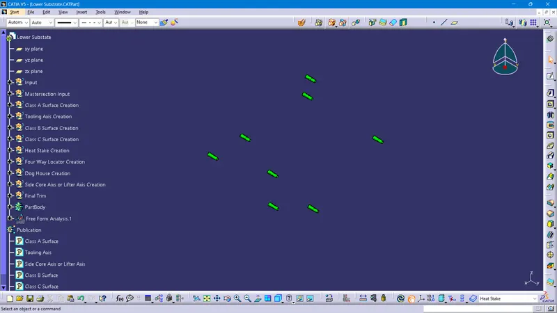
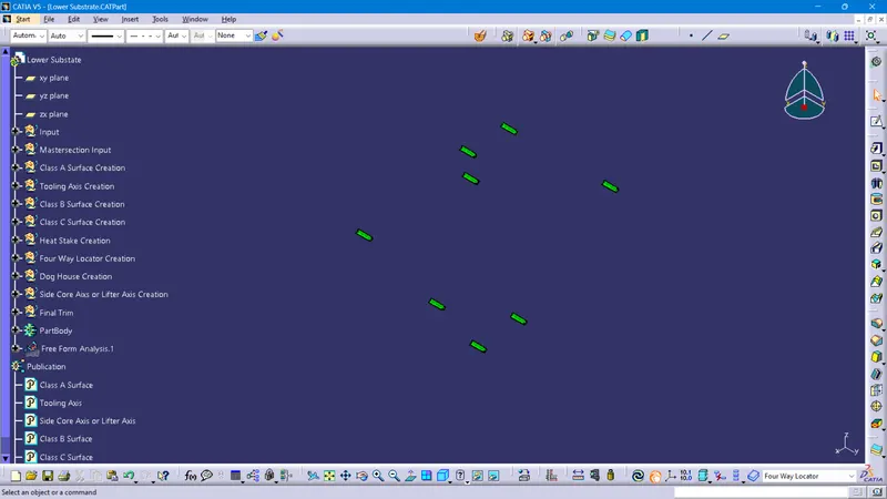
- To Create the Heat stakes and locators in the lower substrate considering the design rules.
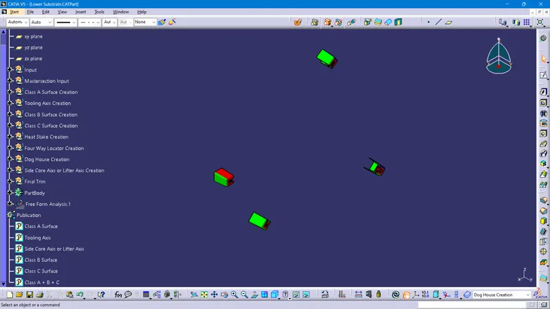
- To Create the Dog house in the lower substrate and assemble the pushpin considering the design rules.
- To Create the Flanges to connect all the design features together considering the design rules.
Introduction Of Automotive Plastic Design
Automotive plastic design is the practice of designing and producing vehicle components using plastic materials. Over the past several decades, the use of plastic in the automotive industry has grown rapidly due to its many advantages over traditional materials such as metal and glass. Automotive plastic design allows for the creation of complex, lightweight, and cost-effective vehicle components that can meet the stringent performance, safety, and regulatory requirements of the automotive industry.
Plastics are versatile materials that can be formulated to meet specific requirements, such as resistance to impact, heat, chemicals, and UV radiation. They can be easily molded into intricate shapes and can be manufactured in large quantities with high precision and repeatability. Automotive plastic design encompasses a wide range of applications, from small interior components like switches and air vents to large exterior parts like bumpers and fenders, as well as engine components, fuel systems, and safety systems.
One of the main benefits of automotive plastic design is its ability to reduce weight, which can improve fuel efficiency, handling, and performance. Additionally, plastic parts can be produced more cost-effectively than metal components, particularly when they are mass-produced using injection molding. Plastic is also more resistant to corrosion than metal and can be engineered to withstand harsh weather conditions and other environmental factors.
Overall, automotive plastic design is a critical component of the modern automotive industry, allowing for the production of vehicles that are lighter, more efficient, and safer than ever before.
Role Of Plastic in the Automotive Industry
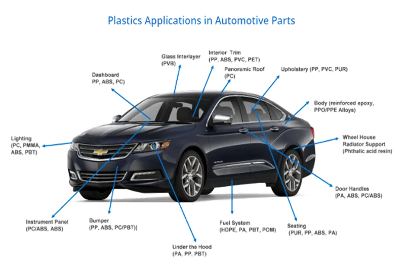
Plastics have played an important role in the automotive industry for several decades. They are used in a wide variety of applications, from exterior body parts to interior components and electrical systems. Here are some of the key ways in which plastics are used in the automotive industry:
Lightweighting: Plastics are lightweight and can help reduce the weight of a vehicle, which can improve fuel efficiency and reduce emissions.
Design flexibility: Plastics can be molded into complex shapes, which allows automotive designers to create unique and aerodynamic designs that are difficult to achieve with other materials.
Durability: Plastics are durable and can withstand exposure to heat, cold, and chemicals, making them ideal for use in harsh automotive environments.
Cost-effectiveness: Plastics are often less expensive than other materials, which can help reduce the overall cost of producing a vehicle.
Noise reduction: Plastics can help reduce noise and vibration in a vehicle, improving overall comfort for passengers.
Safety: Plastics can be engineered to absorb impact and provide crash protection, which is crucial for vehicle safety.
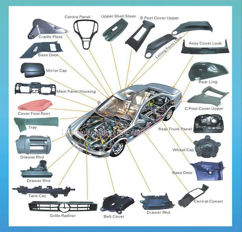
- Some specific applications of plastics in the automotive industry include:
- Exterior body parts such as bumpers, grilles, and body panels
- Interior components such as dashboards, door panels, and seat backs
- Electrical components such as wiring harnesses and connectors
- Engine components such as intake manifolds and valve cover
- Overall, plastics have become a vital material in the automotive industry due to their versatility, durability, and cost-effectiveness. As the industry continues to focus on reducing weight and improving fuel efficiency, it is likely that the use of plastics in automotive applications will continue to grow.
Here Are Four Reasons Why Plastic Is Used in Car Manufacturing
- Plastics reduce the weight of cars
- Plastics and polymers contribute to the safety of cars
- Plastics help to lower car manufacturing costs
- Polymers advance the design of vehicles
Advantages Of Automotive Plastic Design
There are several advantages of using plastic in the design of automotive components:
Lightweight: Plastic parts are typically lighter than their metal counterparts, which can help improve fuel efficiency and overall vehicle performance.
Durability: Automotive plastics are engineered to be tough and durable, which means they can withstand harsh weather conditions, vibrations, and impacts better than some other materials.
Corrosion-resistant: Plastics do not rust, corrode, or rot, making them ideal for use in areas exposed to moisture or salt.
Design flexibility: Plastic can be molded into virtually any shape or size, giving designers and engineers greater flexibility in their designs. This can lead to more innovative and stylish automotive designs.
Reduced costs: Compared to traditional metal fabrication techniques, plastic injection molding can be a more cost-effective process for producing large quantities of parts. Additionally, plastic parts can be easier and cheaper to transport due to their lightweight nature.
Noise and vibration reduction: Some types of plastic can help reduce noise and vibration in the vehicle, leading to a quieter and more comfortable ride.
Eco-friendliness: Automotive plastics can be recycled and reused, making them a more environmentally-friendly choice than traditional metals. Additionally, some types of plastic can be manufactured from renewable resources.
Applications Of Automotive Plastic Design
Automotive plastic design is used in a wide range of applications in the automotive industry, including:
Exterior parts: Plastic is commonly used to make exterior parts such as bumpers, grilles, and fenders, which can help reduce the overall weight of the vehicle and improve its aerodynamics.
Interior parts: Plastic is used for many interior components including dashboards, door panels, and center consoles, as well as smaller items like knobs, switches, and vents.
Electrical components: Plastics are ideal for use in electrical components such as connectors, housings, and circuit boards due to their non-conductive properties and durability.
Engine parts: Plastics are used for a variety of engine components including air intake manifolds, oil pans, and valve covers. These parts can help improve fuel efficiency, reduce noise and vibration, and resist high temperatures.
Fuel systems: Plastic is commonly used in fuel tanks, fuel lines, and fuel rails due to its excellent chemical resistance and ability to withstand the high pressures and temperatures associated with fuel systems.
Lighting systems: Plastics are used to make headlight and taillight lenses, as well as other lighting components. Plastic lenses are durable, lightweight, and can be molded into complex shapes.
Safety systems: Plastics are used in a variety of safety systems, such as airbag housings and seat belt components. Plastic can help reduce weight, absorb impact, and provide increased flexibility and energy absorption in the event of a collision.
Overall, automotive plastic design is a versatile and cost-effective solution that allows for the production of complex and innovative designs while meeting the strict safety and performance standards of the automotive industry.
Manufacturing Process
Injection Moulding
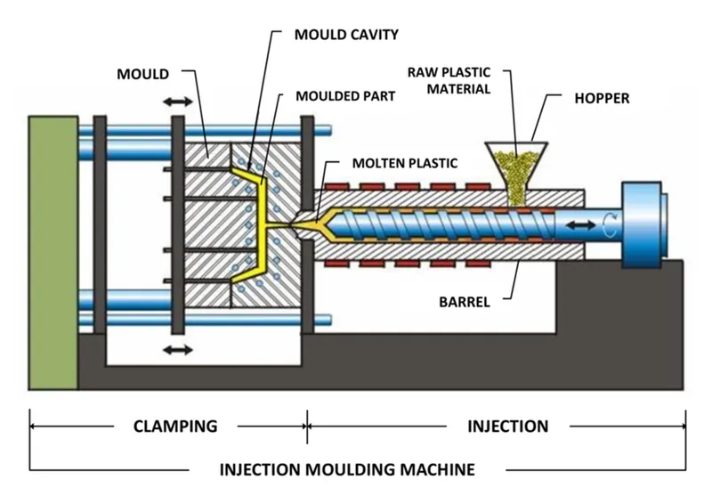
Injection molding is a manufacturing process used to produce plastic parts by injecting molten plastic material into a mold. The process is commonly used for mass production of plastic parts that have a consistent shape and size. The steps involved in injection molding are:
Designing the part: The first step in the injection molding process is to design the part that is to be manufactured using computer-aided design (CAD) software.
Creating the mold: A mold is then created based on the design of the part. The mold is typically made of metal and consists of two halves, a stationary half and a movable half, which can be opened and closed by a hydraulic or mechanical system.
Preparing the material: The plastic material used for injection molding is typically in the form of small pellets or granules. These are loaded into a hopper, which feeds the material into the injection molding machine.
Melting the material: The plastic material is melted in the injection molding machine using a heating element or a screw that melts the material and pushes it into the mold.
Injecting the material: Once the plastic material is melted, it is injected into the mold under high pressure. The mold is held closed by the machine's clamping unit to prevent the plastic from leaking out.
Cooling the part: After the plastic has been injected into the mold, it is allowed to cool and solidify. The cooling time depends on the thickness of the part and the specific plastic being used.
Ejecting the part: Once the part has cooled and solidified, the mold is opened and the part is ejected from the mold using ejection pins or a robotic arm.
Repeat: The process is then repeated to produce additional parts.
Injection molding is a versatile and efficient process that can produce parts with a high level of accuracy and consistency. The process is widely used in industries such as automotive, medical, consumer goods, and packaging.
Tooling Direction for Plastic Part
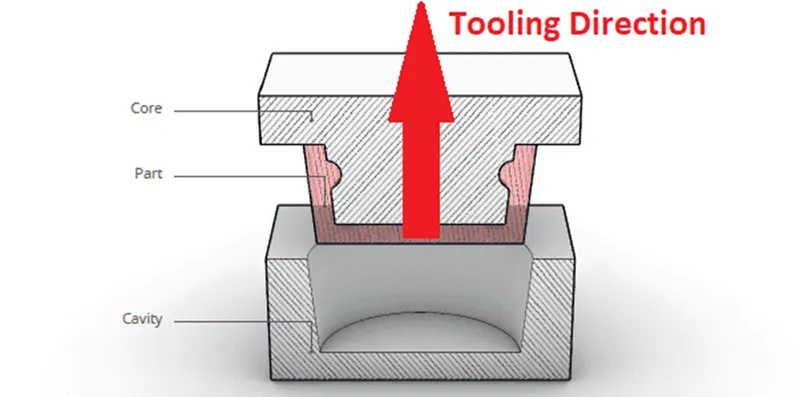
Tooling direction is a primary consideration for plastic parts and mold parts because it defines the movement of the mold part and the possibility of the plastic part coming out from the mold part (Core and Cavity).
In Molding, machine arrangement is given to open the mold along a direction which is known as Tooling Direction.
In other words. The mold is built from two separate halves (Core and Cavity) and the tooling direction basically defines the direction of the mold pulls apart.
Tooling direction is known as primary direction.
The core is the male part of the mold which holds the inner design of the component and the cavity is the female part which holds the outer shape of the component.
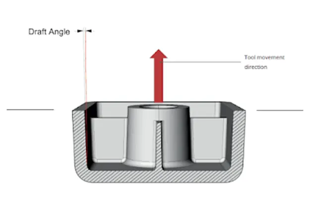
Tooling direction, also known as mold flow direction, refers to the direction in which the molten plastic material flows into a mold during the injection molding process. The direction of the flow can have an impact on the properties and appearance of the finished product, as well as the ease and efficiency of the molding process.
When designing a mold for injection molding, the tooling direction is an important consideration. The tooling direction can affect the strength, appearance, and function of the finished part. The tooling direction also impacts the flow of plastic material in the mold, which can affect the filling and packing of the part.
There are generally two types of tooling direction: a longitudinal tooling direction and a transverse tooling direction. A longitudinal tooling direction is parallel to the longest dimension of the part, while a transverse tooling direction is perpendicular to the longest dimension of the part. The choice of tooling direction depends on the specific requirements of the part being molded and the desired properties of the finished product.
The tooling direction can also affect the cost and complexity of the mold. A mold with a transverse tooling direction may require more complex and costly tooling, as the plastic material needs to flow through thinner sections of the mold. In contrast, a mold with a longitudinal tooling direction may require less complex tooling and can be more cost-effective.
In summary, tooling direction is an important consideration in the injection molding process, as it can impact the properties, appearance, and efficiency of the molding process. The choice of tooling direction depends on the specific requirements of the part being molded, the desired properties of the finished product, and the cost and complexity of the mold.
Car Door Panel
Door panels serve as an interface between the interior of the car, the inner workings of the door, and between vehicle occupants and the door. They are expected to meet a variety of design specifications regarding safety, aesthetics, and functionality. In addition, they are expected to continue the material theme of the dashboard and pillars while concealing intricate electrical and mechanical components for operating locks, windows, and other features. The door panel has evolved from a simple two-part system of the latch and simple winding mechanism to a more sophisticated enclosure. Doors currently have an inner full-width panel consisting of electronic windows, a central locking system, and speakers. These panels typically consist of a foamed core covered with either textiles or plastics.
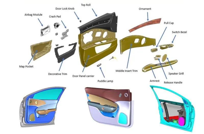
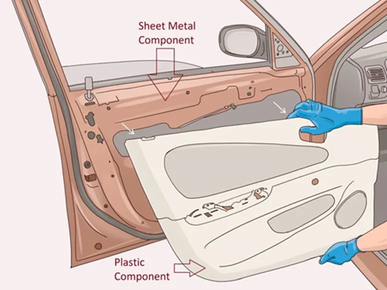
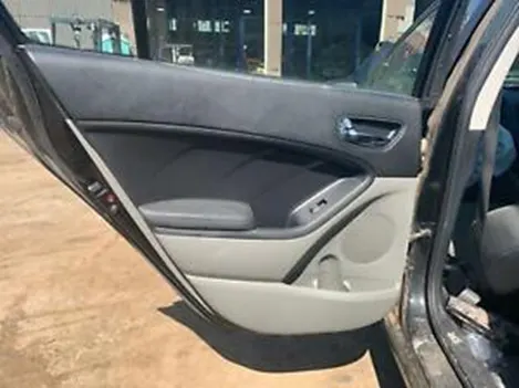
Door panels are expected to meet one of the toughest sets of requirements among interior car components. These panels should be designed to withstand and channel loads into the body of the car while being thin (<2 mm). These loads could be horizontal and vertical in nature, like the force applied on opening or closing doors while leaning/resting on them or when stepping on the armrest to access the roof. An additional consideration is their ability to protect occupants from injury during a side collision, where most injuries are inflicted on the chest and pelvis as a result of the crushing force of the door.
Federal Motor Vehicle Safety Standard No.214, therefore, sets forth directives to manufacturers in order to limit this injury. It states that the Thoracic Trauma Index (TTI) should not exceed 85 g for a four-door or 90 g for a two-door passenger car. This test is performed at an impact velocity of 53 km/h, which accounts for 90% of side impacts in North America.
Conventionally, door panels consisted of polyvinyl chloride (PVC) or polyurethane foamed core with appropriate textile fabric coverings. Subsequently, there was a shift toward thin-wall moldings of ABS or PP backed by textiles in order to manufacture a contour-backed panel with recesses. This is primarily because integrated injection-molded door panel assemblies reduce the need for other energy-absorbing materials, resulting in cost reduction for manufacturers due to the simplification of door construction.
The door currently has an inner full-width panel consisting of electronic windows, a central locking system, and speakers. These panels typically consist of a foamed core covered with either textiles or plastics.
Introduction
Create the Door Trim Lower with Engineering Features and Plastic components through the given Class-A surface. To begin with, the tooling axis for the given Class-A Surface should be created meeting the requirements of the draft angle, and also design Four-way and Two locators, Heat Stakes, a Dog House, and a Rib at the end to perform the Draft analysis on the model.
Tooling axis Creation
In injection molding, the Class A surface is first analyzed to determine the axis or tooling direction that separates the molds. Tooling direction is critical for plastic product design because it determines mold direction
Tooling Axis for Arm Rest
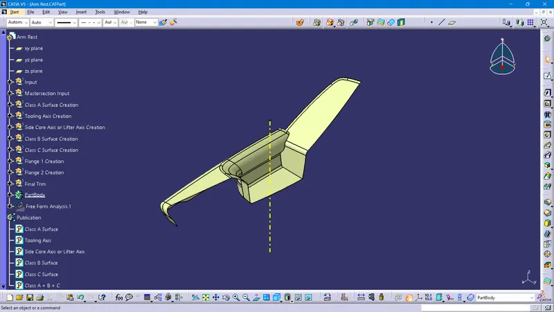
Tooling Axis for Lower Substrate
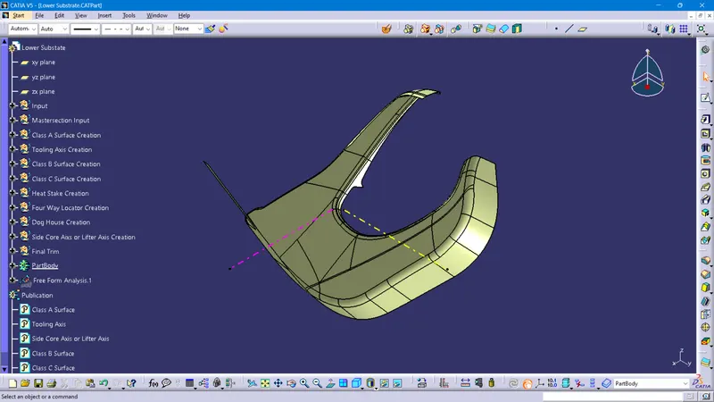
Tooling Axis for Map Pocket
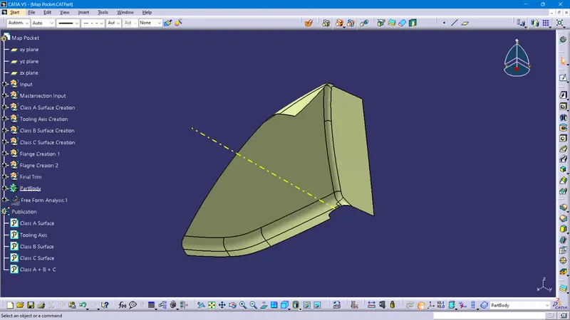
Tooling Axis for Bottle Holder
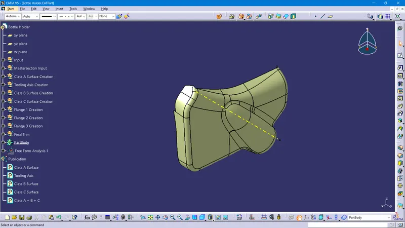
What is Draft Analysis?
Draft Analysis
For molded or cast parts, the draft angle is the amount of taper perpendicular to the parting line. It is measurable in degrees. Because plastic shrinks and sticks on molding surfaces as it cools, we draft the walls of the plastic part so that it ejects or breaks free from the molding surfaces more easily and without dragging. To reduce the risk of damage to the parts and ensure ejection, a functional injection molding part must have drafts on both the cavity and core sides.
Nominal values for Draft angles
- 3 Degrees is a nominal draft angle
- 5 Degrees can also be manufactured. Increasing the manufacturing cost
- 7 Degrees is considered for Textured surface parts
Importance of Draft in injection molding
- Reduces the possibility of part damage due to friction during the release
- Reduces mold wear and tear
- Ensures a uniform, smooth, unscratched finish
- Ensures the integrity and uniformity of other surface finishes and textures
- Reduces overall cooling time by reducing or eliminating the need for unusual ejection setups
Steps followed for Draft Analysis
- The created part must be changed to the material mode in the display frame
- Compass is enabled and placed in the direction of the Tooling Axis
- The lock command is then used to fix the compass along the tooling axis
- Color codes are classified and a Draft angle is applied
- Running point analysis is used to display permissible draft angle
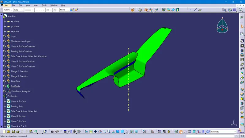
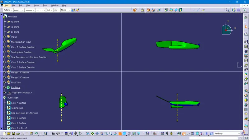
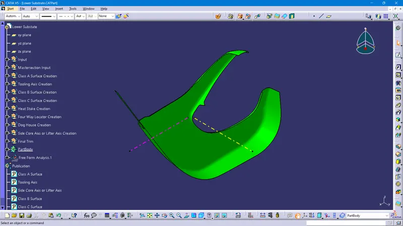
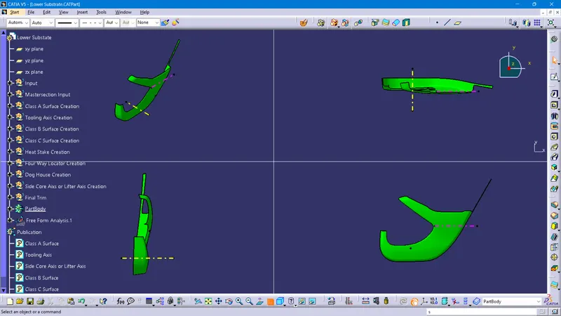
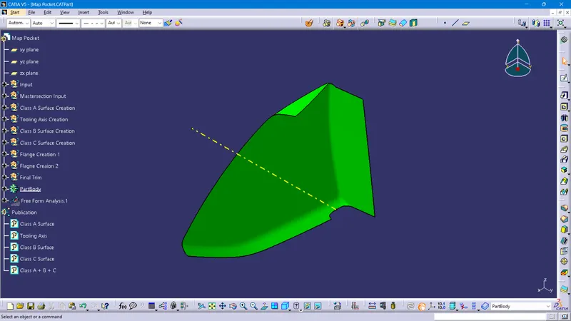
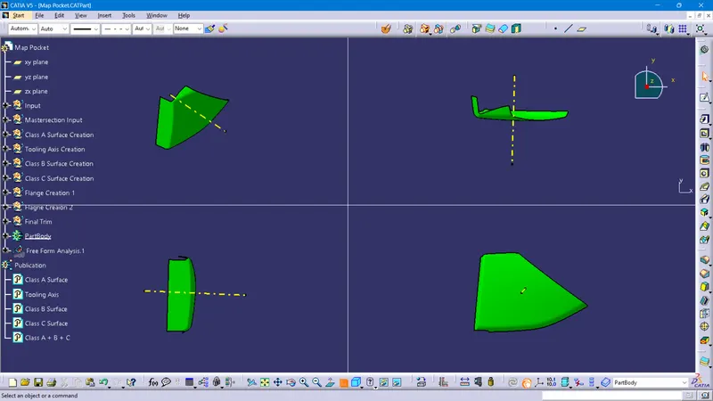
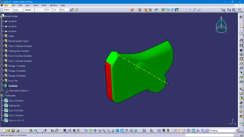
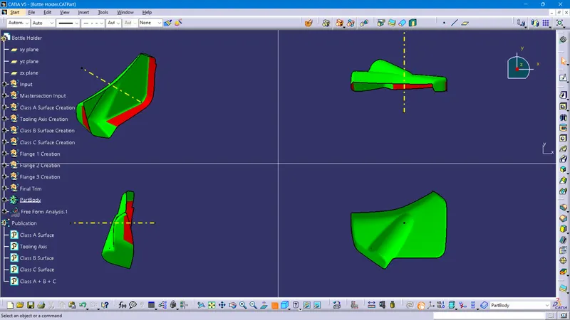
For the given Class A Surface, the draft analysis is been performed in order to determine whether the part is cleared with the draft angle of 3 degrees. But with the given Class A Surface is not cleared with the 3 Degree draft angle for the respective tooling direction. It will be cleared when the class A team should rework it.
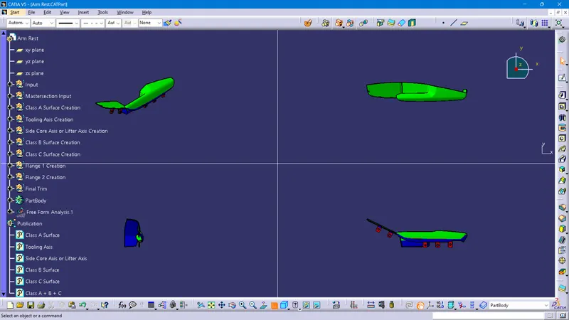
Draft Analysis for Arm Rest
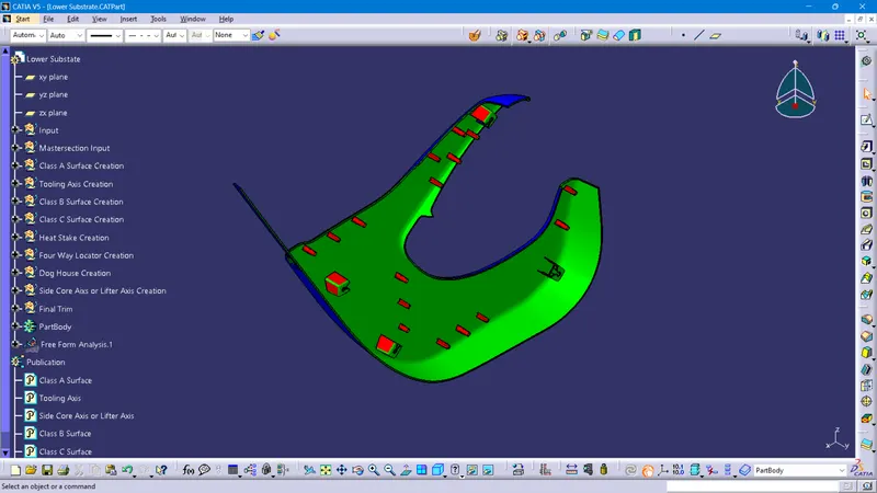
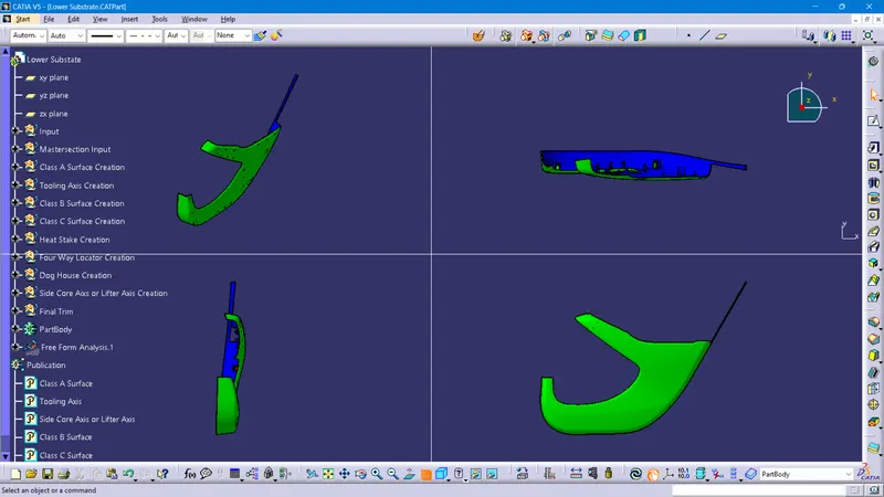
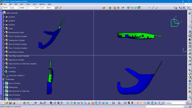
Draft Analysis for Lower Substrate
Draft Analysis for Map Pocket
Draft Analysis for Bottle Holder
Input given: Class A surface of Arm Rest
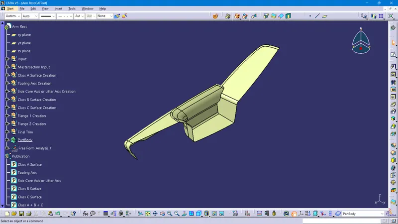
Creation of Class B Surface of Arm Rest
It is the offset surface of the Class A Surface the offset value depends on the thickness of the material, here the offset value is 2.5mm
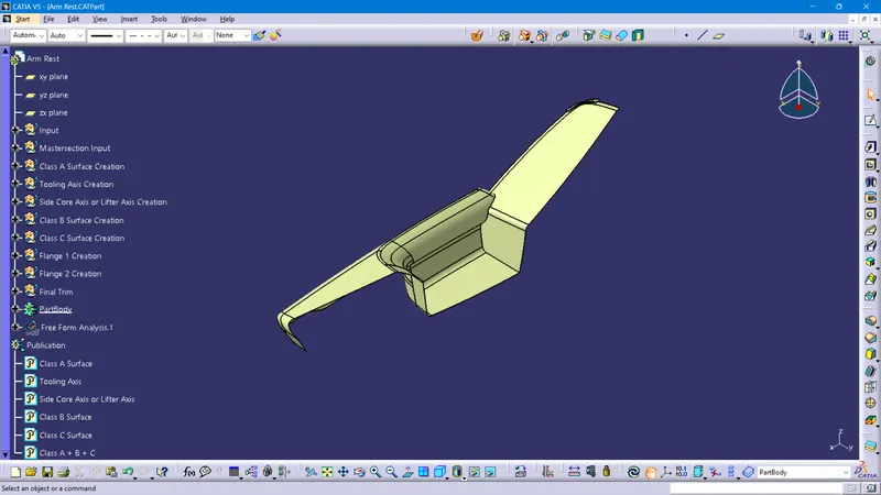
Class C surface of Arm Rest
The surface that Joins both Class A and Class B surfaces is considered to be Class C Surface
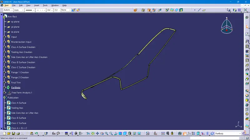
Class (A+B+C) of Arm Rest
Here we combine all the surfaces into one closed surface using the Trim tool Command
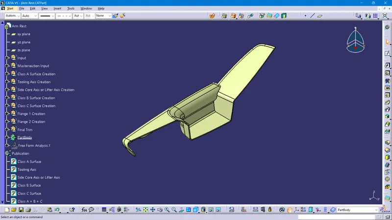
Conversion of Closed surface into Solid Part of Arm Rest
Using Solid Command, we convert the closed surface to a solid surface in the Part model
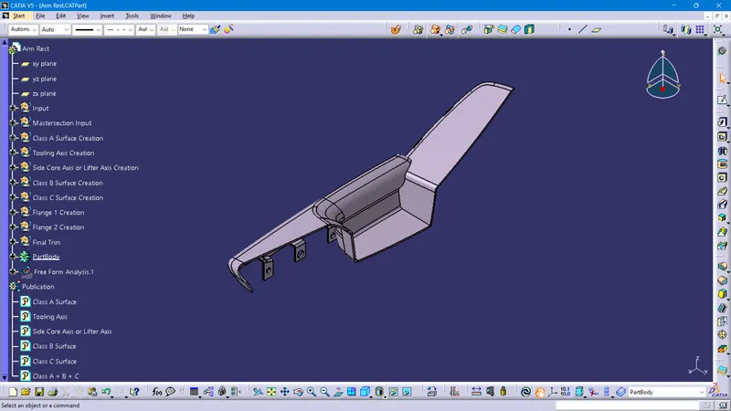
Input given: Class A surface of Lower Substrate
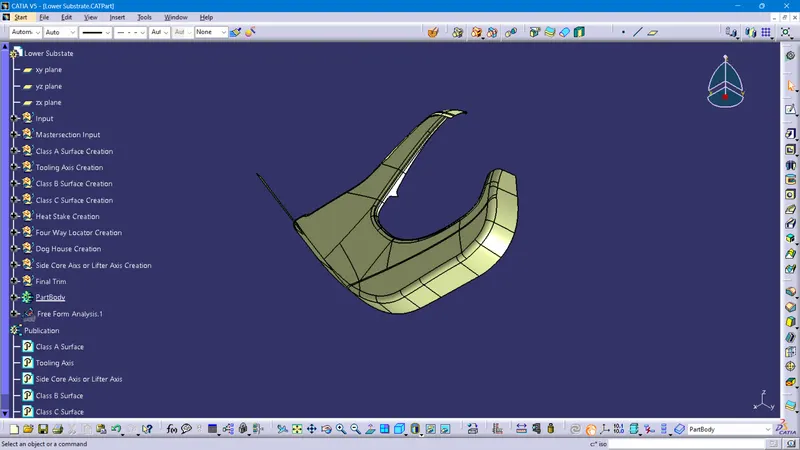
Creation of Class B Surface of Lower Substrate
It is the offset surface of the Class A Surface the offset value depends on the thickness of the material, here the offset value is 2.5mm
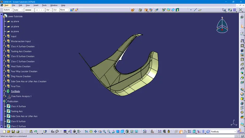
Class C surface of Lower Substrate
The surface that Joins both Class A and Class B surfaces is considered to be Class C Surface
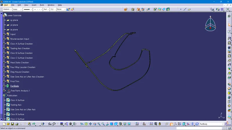
Class (A+B+C) of Lower Substrate
Here we combine all the surfaces into one closed surface using the Trim tool Command
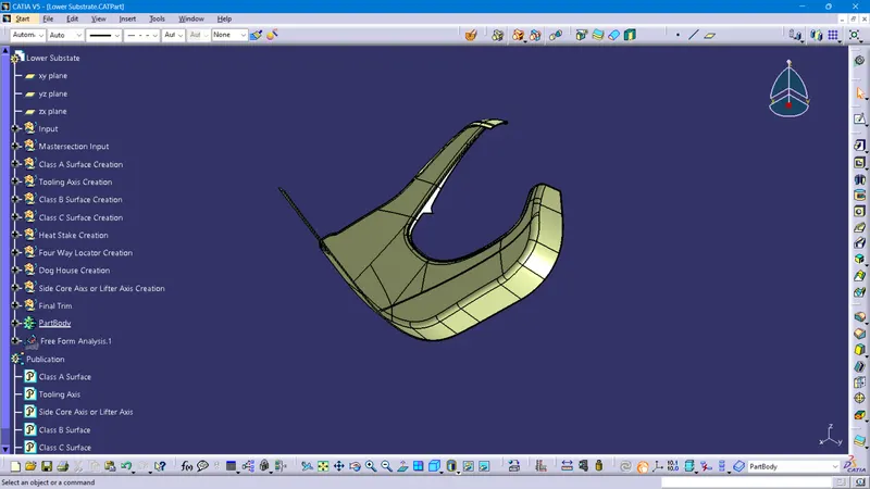
Conversion of Closed surface into Solid Part of Lower Substrate
Using Solid Command, we convert the closed surface to a solid surface in the Part model
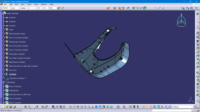
Input given: Class A surface of Map Pocket
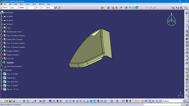
Creation of Class B Surface of Map Pocket
It is the offset surface of the Class A Surface the offset value depends on the thickness of the material, here the offset value is 2.5mm
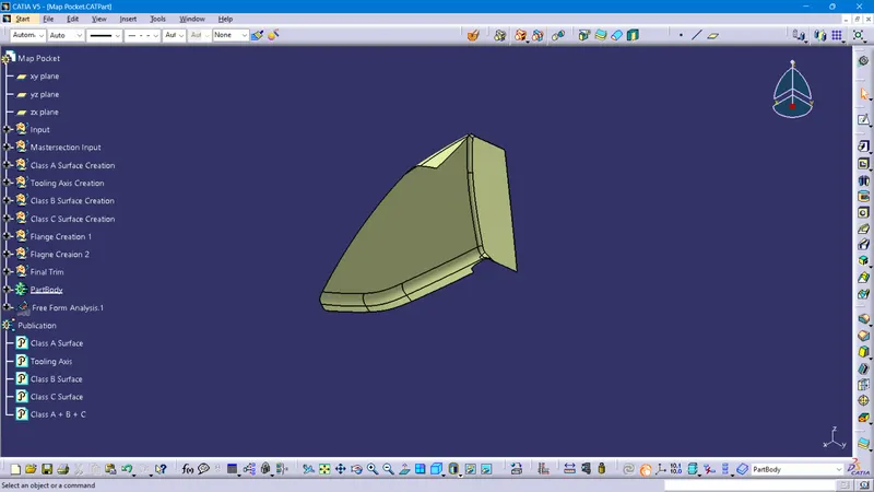
Class C surface of Map Pocket
The surface that Joins both Class A and Class B surfaces is considered to be Class C Surface
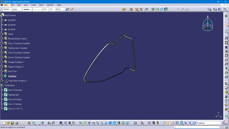
Class (A+B+C) of Map Pocket
Here we combine all the surfaces into one closed surface using the Trim tool Command
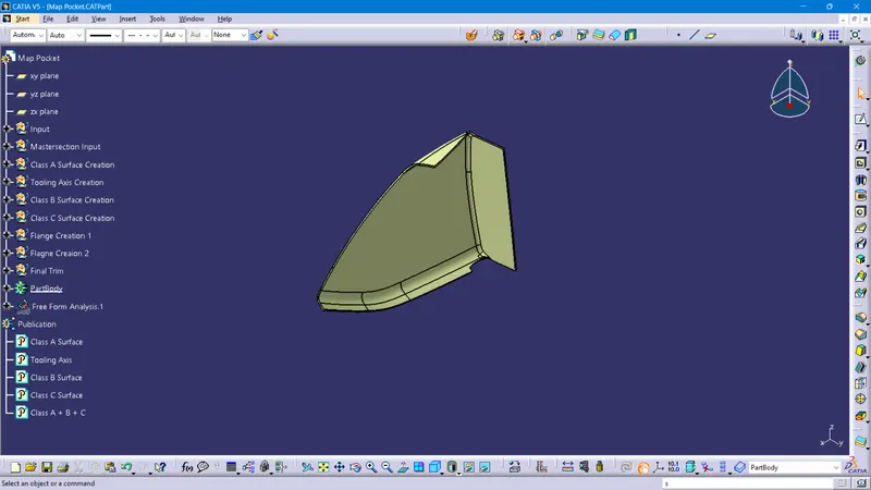
Conversion of Closed surface into Solid Part of Map Pocket
Using Solid Command, we convert the closed surface to a solid surface in the Part model
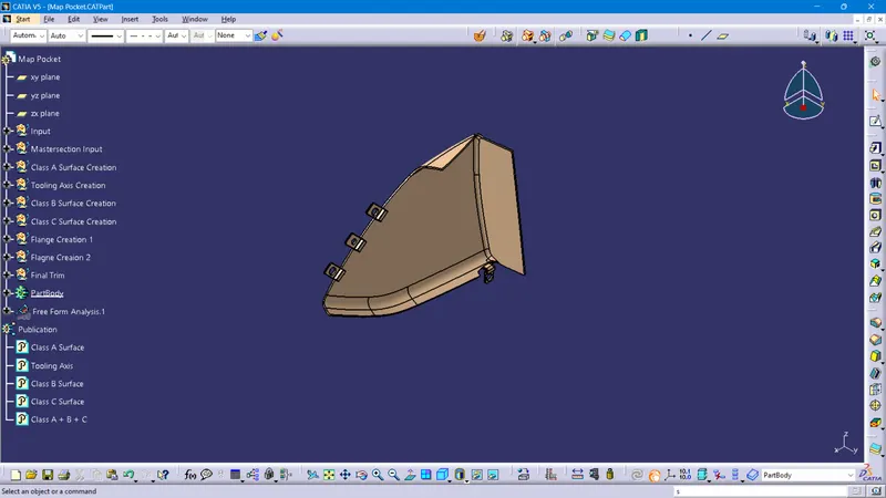
Input given: Class A surface of Bottle Holder
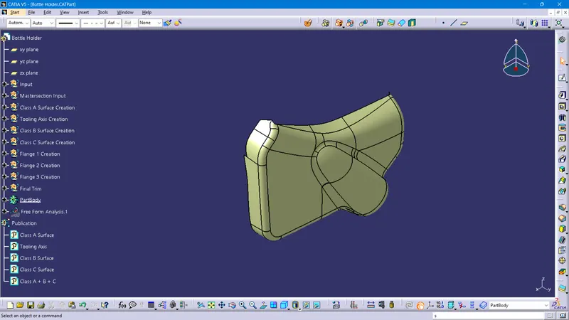
Creation of Class B Surface of Bottle Holder
It is the offset surface of the Class A Surface the offset value depends on the thickness of the material, here the offset value is 2.5mm
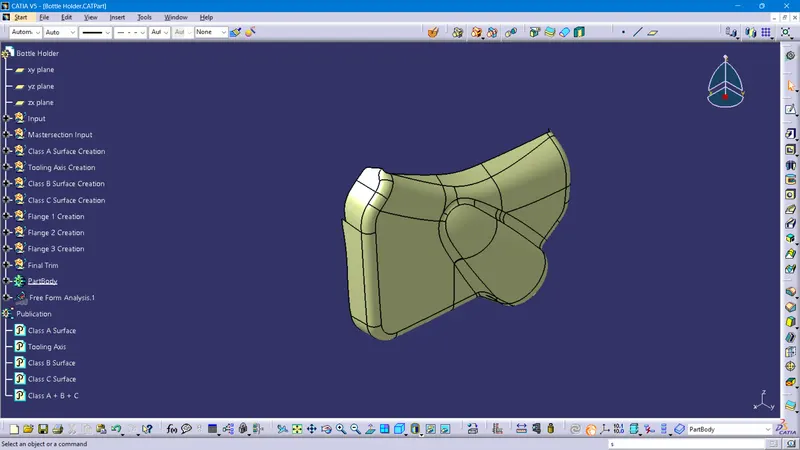
Class C surface of Bottle Holder
The surface that Joins both Class A and Class B surfaces is considered to be Class C Surface
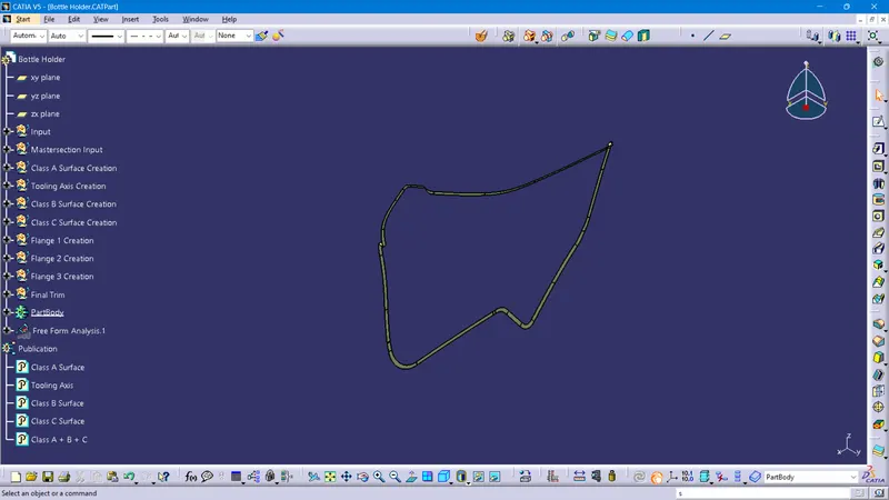
Class (A+B+C) of Bottle Holder
Here we combine all the surfaces into one closed surface using the Trim tool Command
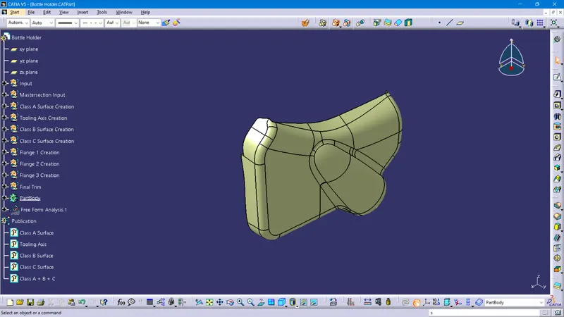
Conversion of Closed surface into Solid Part of Bottle Holder
Using Solid Command, we convert the closed surface to a solid surface in the Part model
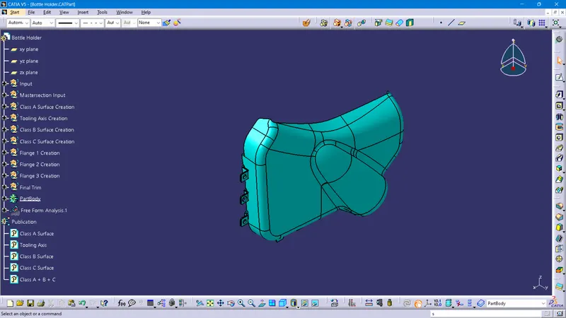
Creating B Surface Engineering Features Like Flanges Four-Way and Two-Way Locators, Heat Stakes, Dog Houses, and Ribs
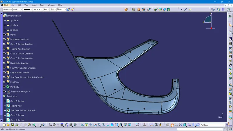
Creating Four-Way Locators on B Surface
Locators are mainly used to Arrest the Degrees of Freedom of the Plastic Component. Usually, there are 2-way and 4-way Locators. It also supports the Position of Plastic Component While Assembly or Joining Components.
A 2-way locating pin restricts motion along 1 axis (or 2 degrees of Freedom), like a round pin in a slot. Likewise, a 4-way pin restricts 4 degrees of freedom along 2 axes. A round locating pin located concentrically in a hole is a common application of a 4-way pin and helps to further secure the piece. 4-way mean you prevent movement at 2 axes (+X, -X, +Y and -Y) on the plane. Generally, you have a cylindrical pin on the fixture and a circular hole at the workpiece part.
Any workpiece has 12 degrees of freedom for movement in space that consists of 6 Axial and 6 Radial Degrees of Freedom. All 12 degrees of freedom must be restricted to ensure proper referencing of a workpiece. These 6 Axial Degrees of Freedom permit Straight-Line Movement in both directions along the 3-principle axis shown as X, Y & Z. The Radial Degrees of Freedom permit Rotational Movement, in both Clockwise & Counterclockwise radial directions around the same three axes.
We have two objectives when assembling the child component with the parent component:
- Accurately position the part at the desired coordinates.
- Restrict all degrees of freedom except the one direction in which it'll fix so that the part cannot move.
Creating Heat Stakes on B Surface
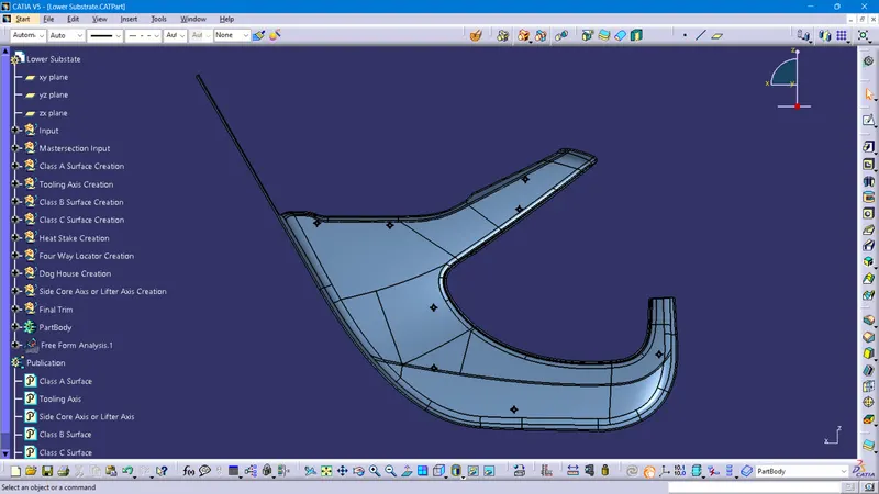
Manufacturing operations currently use many different combinations of attachment methods to keep components together. Common fasteners such as bolts, screws, and rivets can be used to form permanent attachments, but there are attachment methods that don’t require secondary hardware. One of those methods is heat staking, which doesn’t require additional fasteners. Heat staking also known as Thermoplastic staking is the process of joining two Plastic Components together.
Gussets are Support Features that Reinforce Areas such as Walls or Bosses to the floor. Just as bridge beams and columns are supported at their vertex with gussets to add critical strength to the structure, the same concept applies to plastic injection molding.
The difference between Ribs and Gussets is that ribs are usually thin wall supports added internally around walls to achieve better geometry and support. Gussets, on the other hand, are thicker wall supports to add strength and reinforcement to existing plastic features.
Recommended Thickness of a Gusset at the Wall is 50% of the Wall Thickness. Typically, the gusset height is less than four times the wall thickness, preferably two times the wall thickness.
Creating Dog House on B Surface
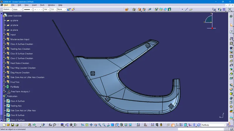
Dog houses are designed to avoid Sink Marks created on the CLASS-A surface by screw bosses and to solve the length issues when giving screw bosses which need to be assembled to other components. It is also useful when perpendicular screw bosses are required on the part of the tooling direction.
The dog house is an engineering feature used in the plastic trim design. Dog houses are used as supporting features. Sometimes other engineering features like snaps, locators, etc. are mounded on them to increase their strength. Dog house and other engineering Features are built on B-surface.
Design Rules For Dog House Creation
"C" is where the doghouse contacts the backside of the surface
Doghouse wall thickness at the intersection of the part wall (C) should be 40% or less than the main wall stock (T).
The height of (B) should be between 3.0 – 6.0 mm
C 40 % of T or ≤ T
B 3 - 6 mm
Width ≥12 mm
Width to Height Ratio 3:1
Draft 1.5
Side Core Axis or Lifter Axis
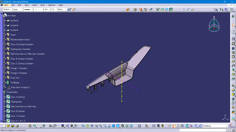
The side core axis is also a type of Tooling Axis, we can say it is an additional tooling axis for sub-elements on our part body in different axis.
Here we used the axis for inside clearance for the dog house part.

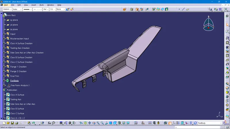
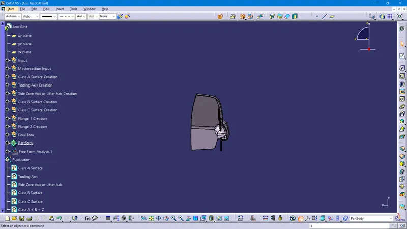
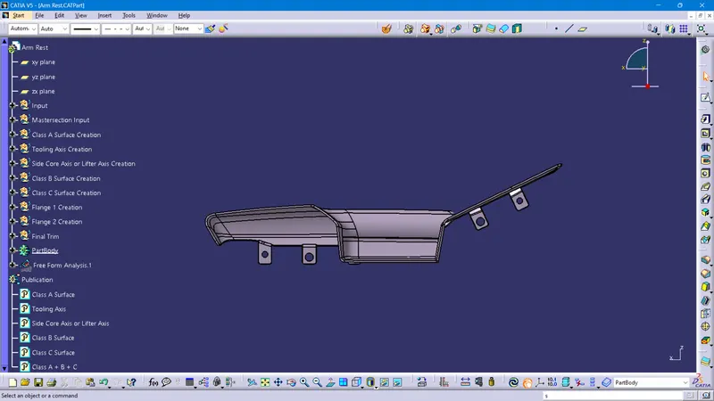
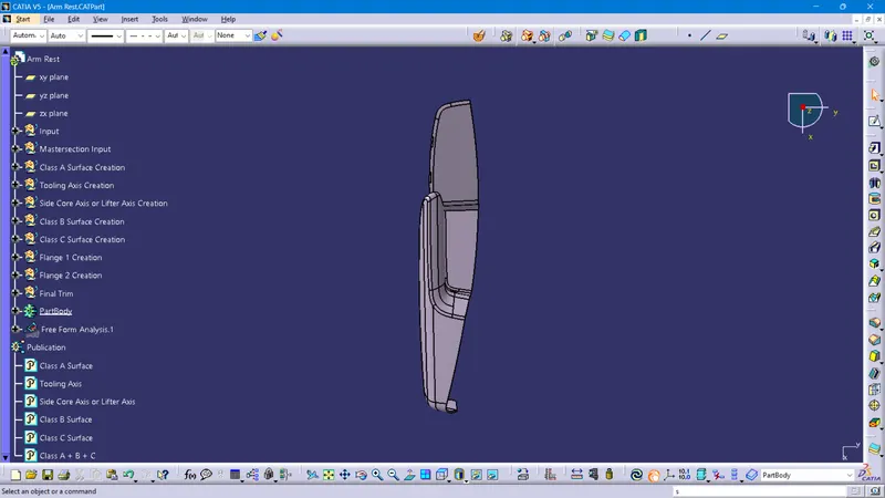
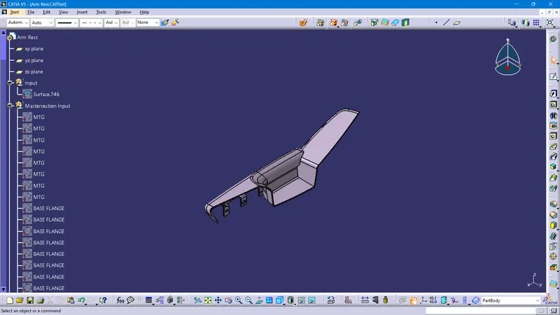
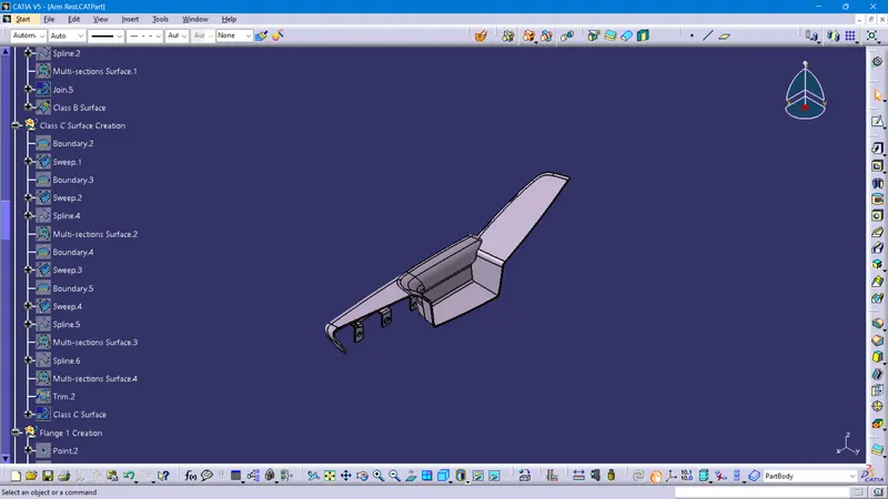
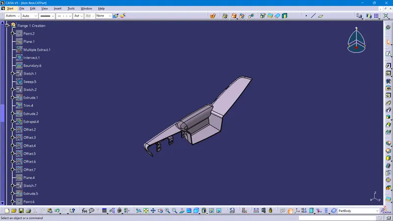
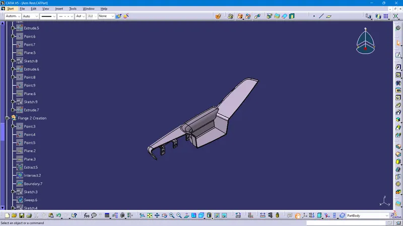
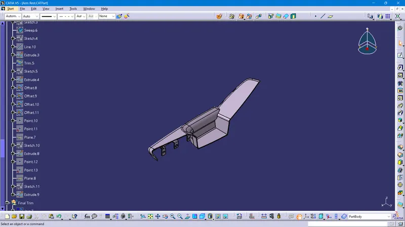
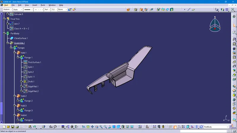
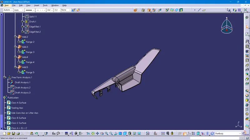
Views of the Arm Rest
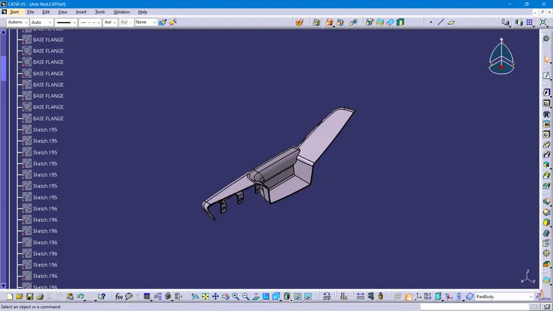
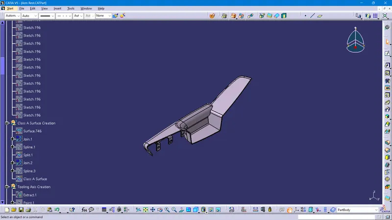
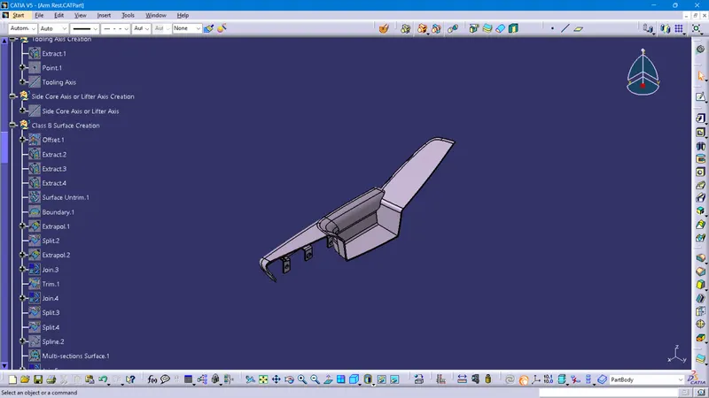
Feature Tree of Arm Rest
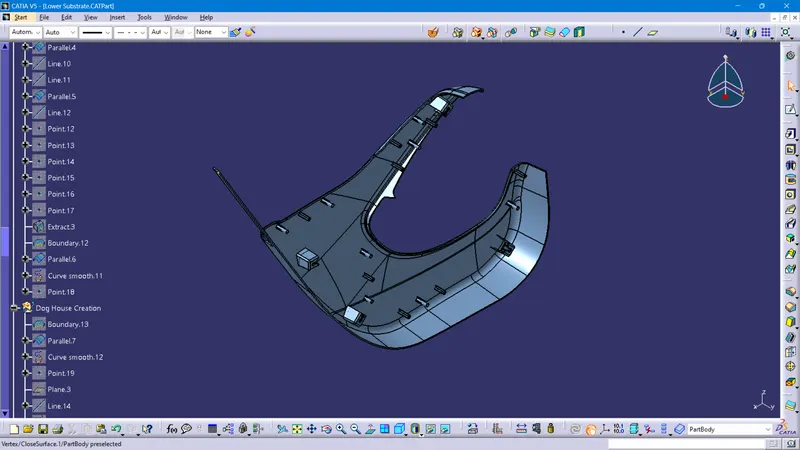
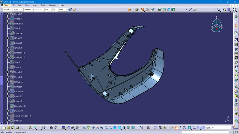
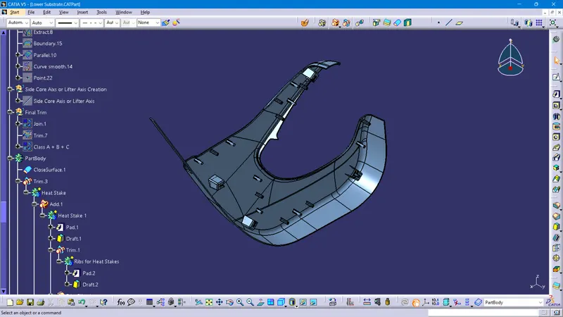
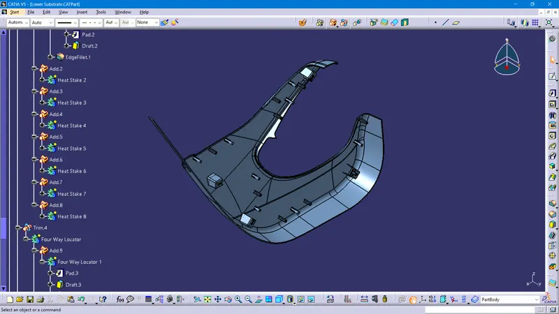
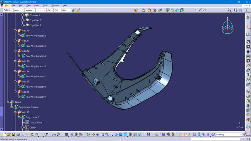
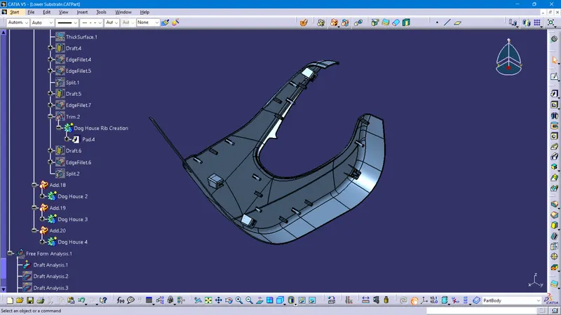
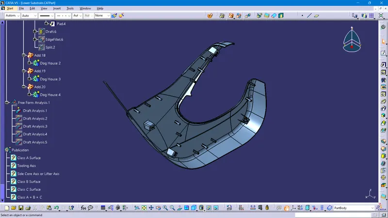
Views of the Lower Substrate
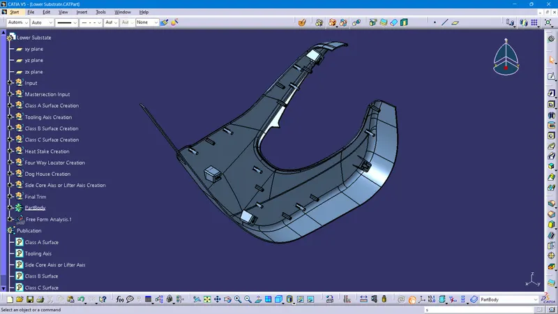
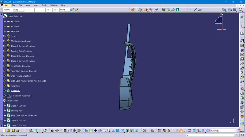
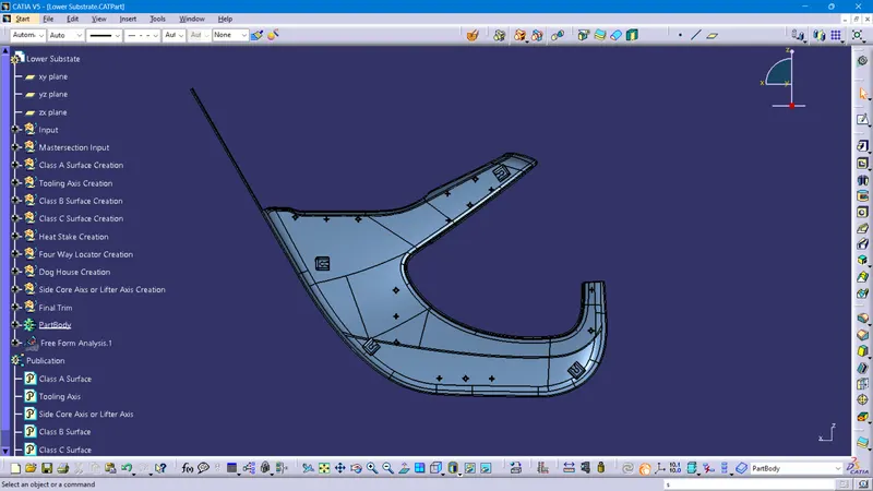
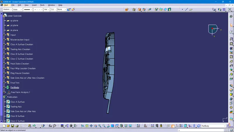
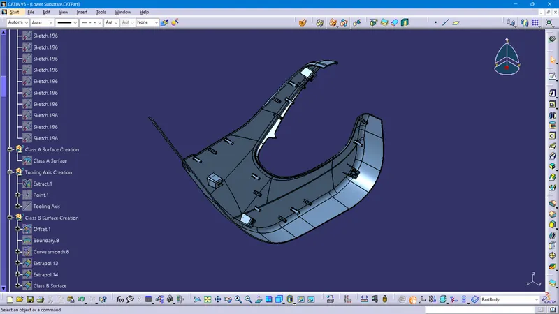
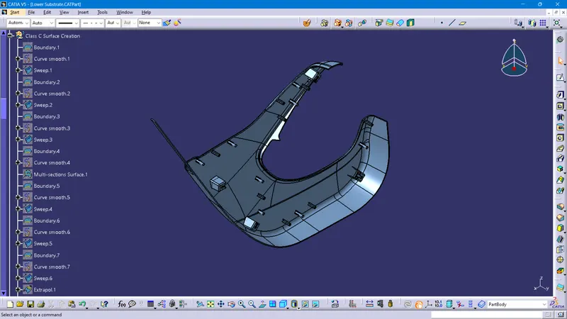
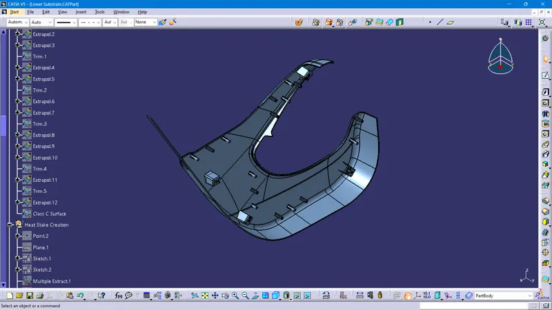
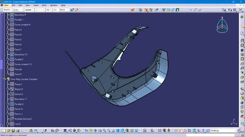
Feature Tree of Lower Substrate
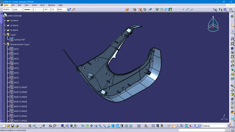
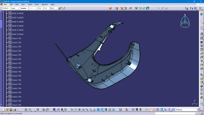
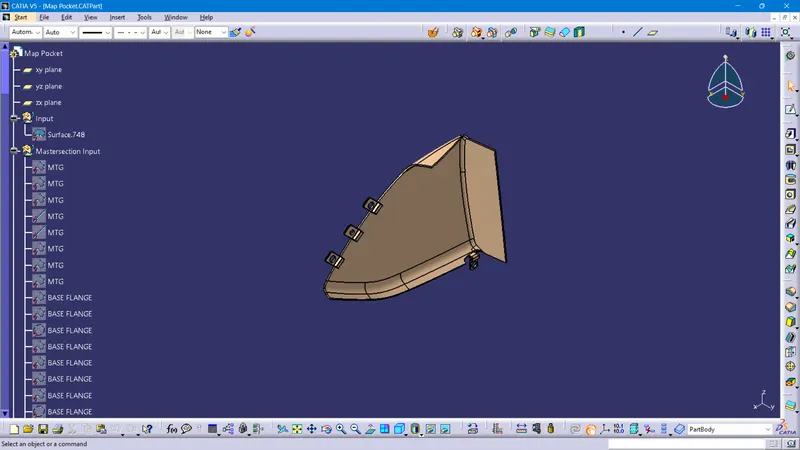
Views of the Map Pocket
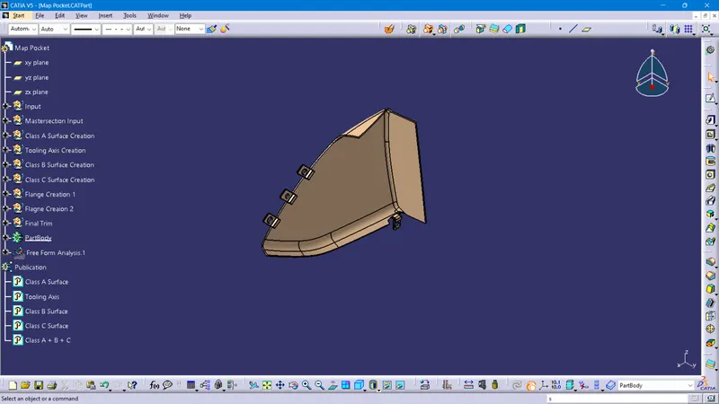
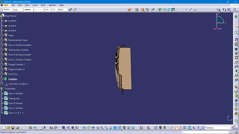
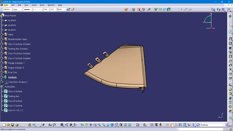
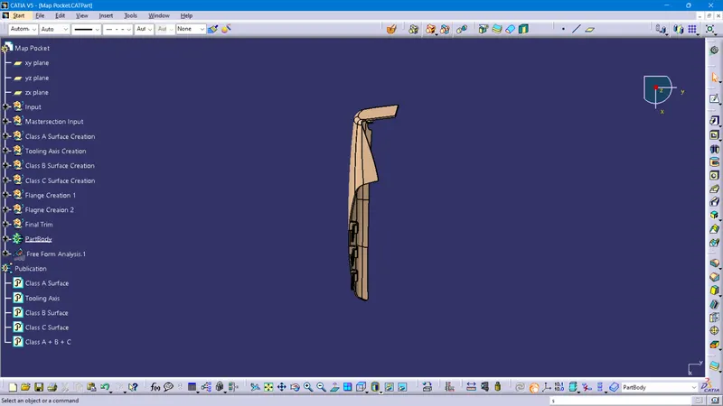
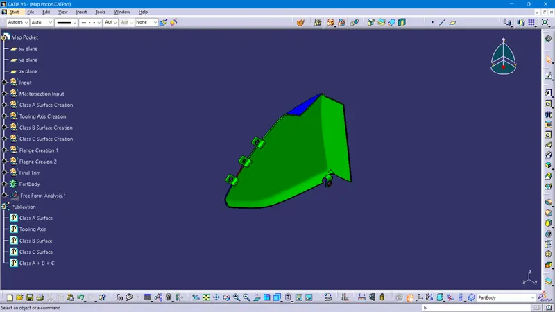
Feature Tree of Map Pocket
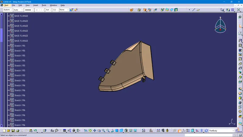
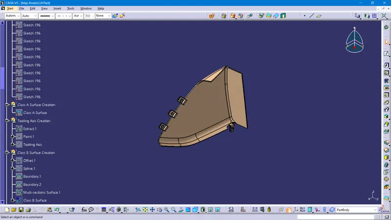
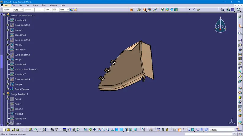
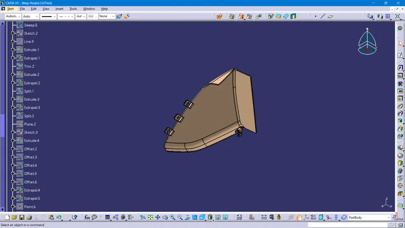
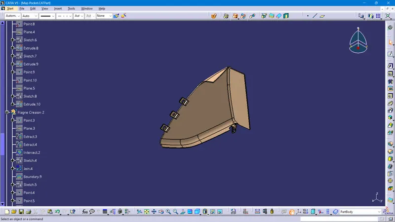
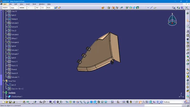
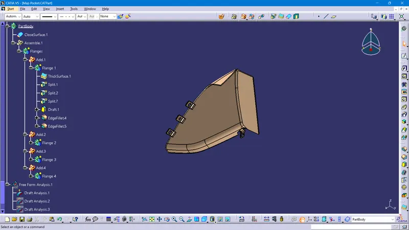
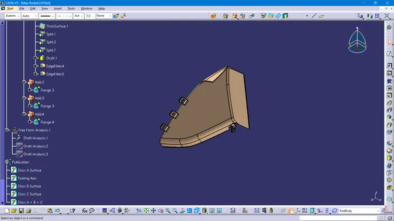
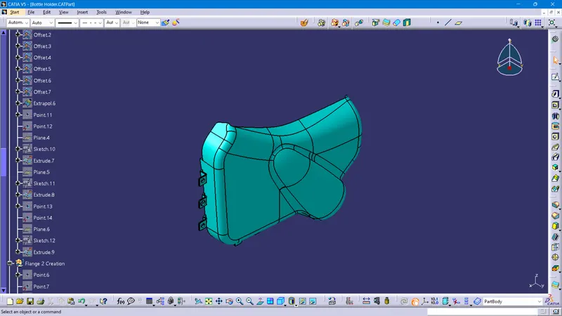
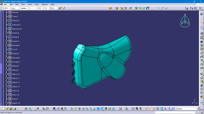
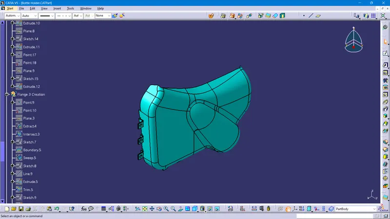
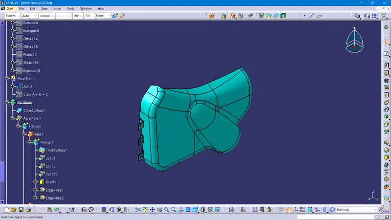
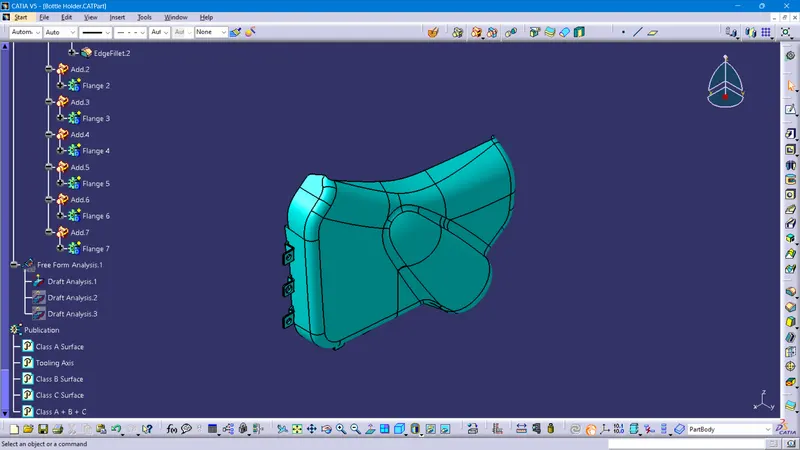
Views of the Bottle Holder
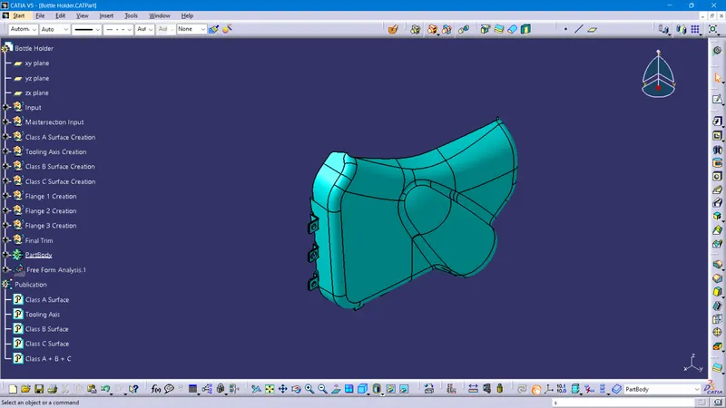
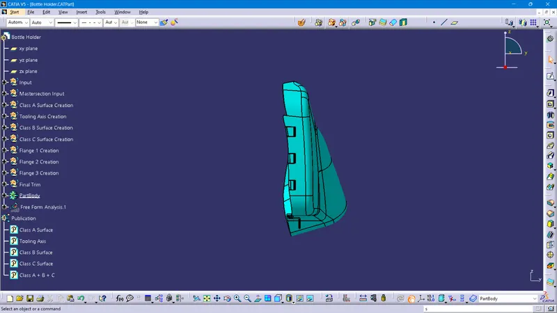
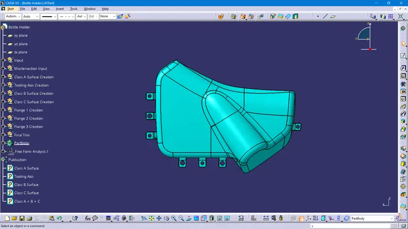
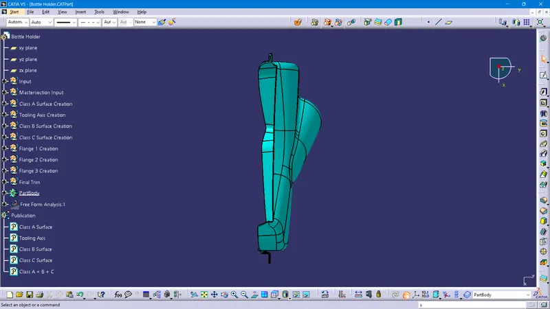
Feature Tree of Bottle Holder
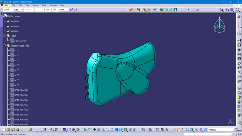
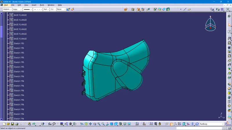
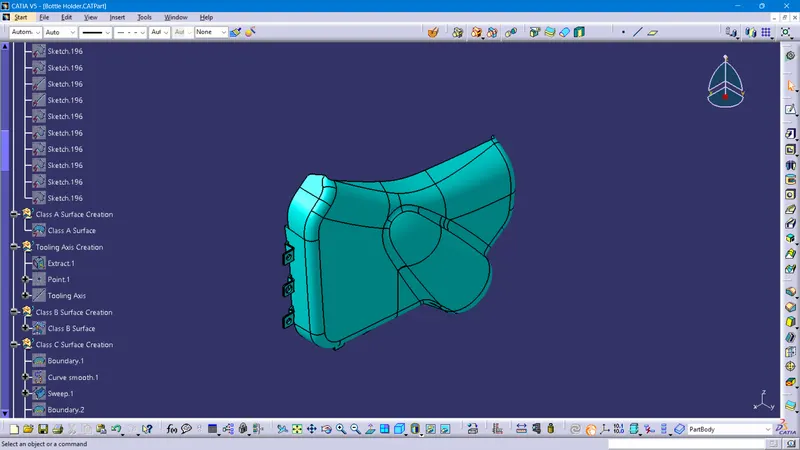
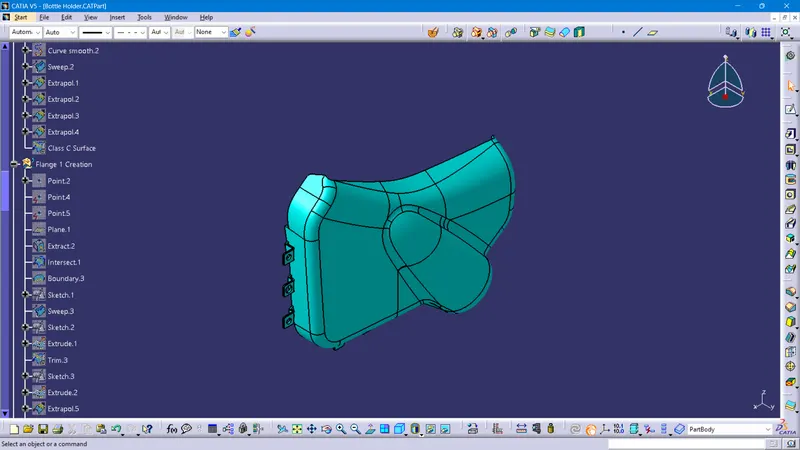
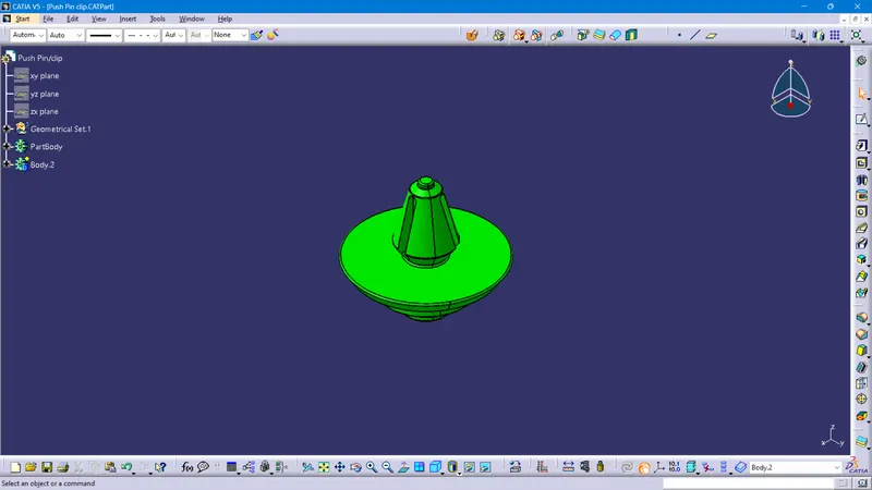
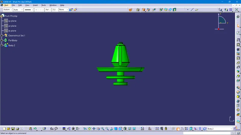
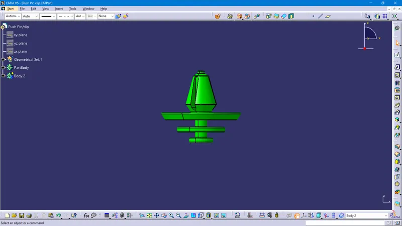
Views of the Push Pin or Clip
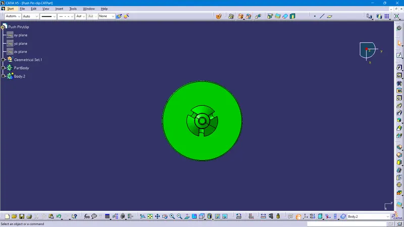
Feature Tree of Push Pin or Clip
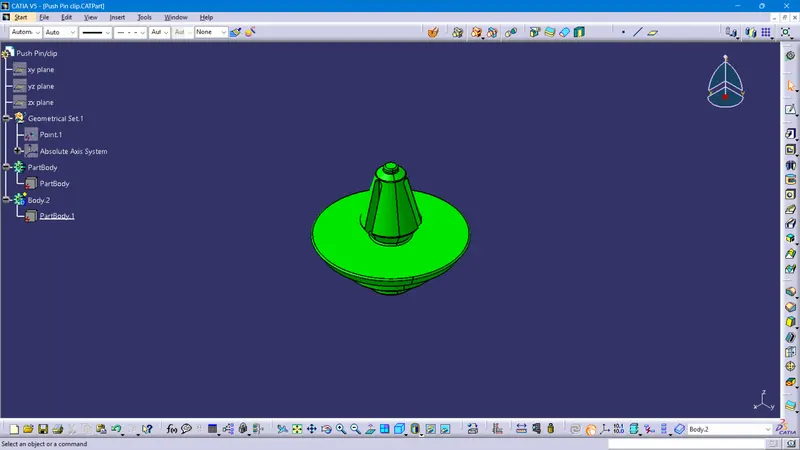
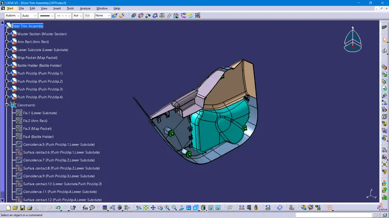
Views of the Assembly
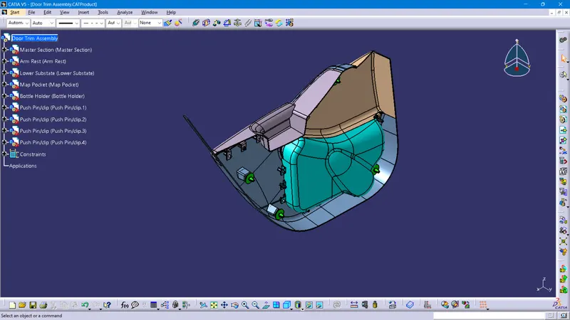
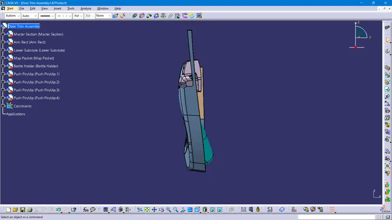
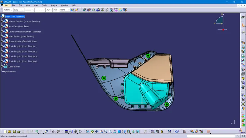
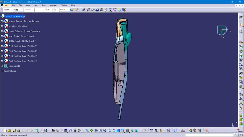
Feature Tree of Assembly
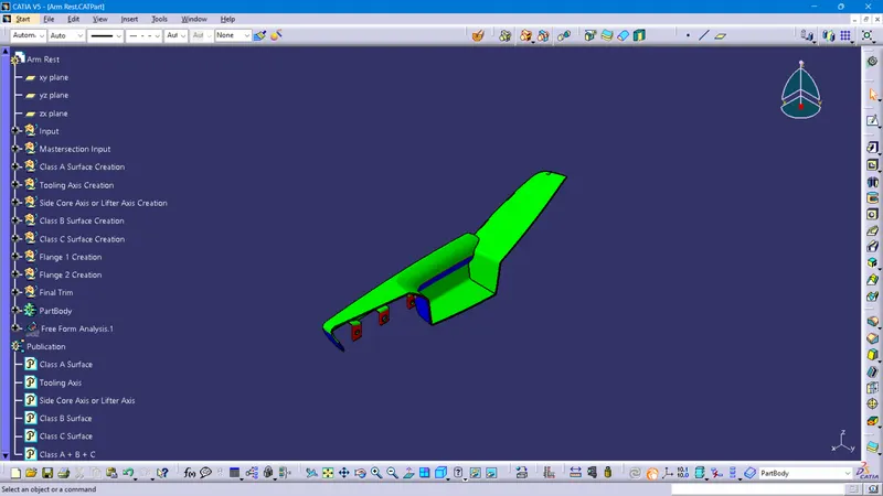
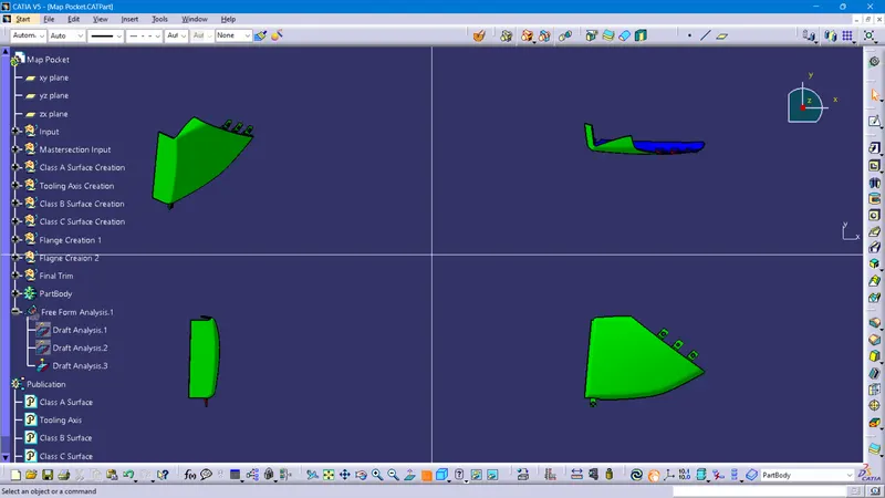
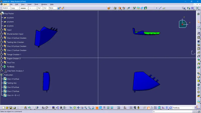
Performed draft analysis closed surface.
The green color indicates drafted walls above 3 deg.
The red color indicates drafted walls from 0-3 deg.
The Blue color indicates negative deg.
Draft Analysis for Arm Rest
Draft Analysis for Lower Substrate
Draft Analysis for Map Pocket
Draft Analysis for Bottle Holder
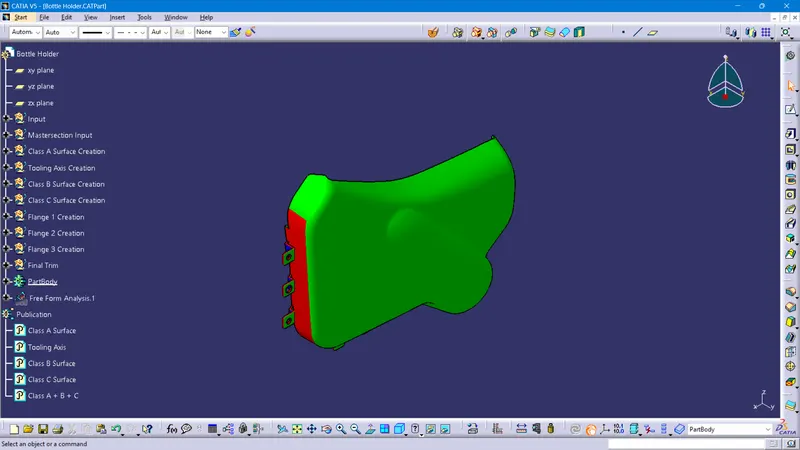
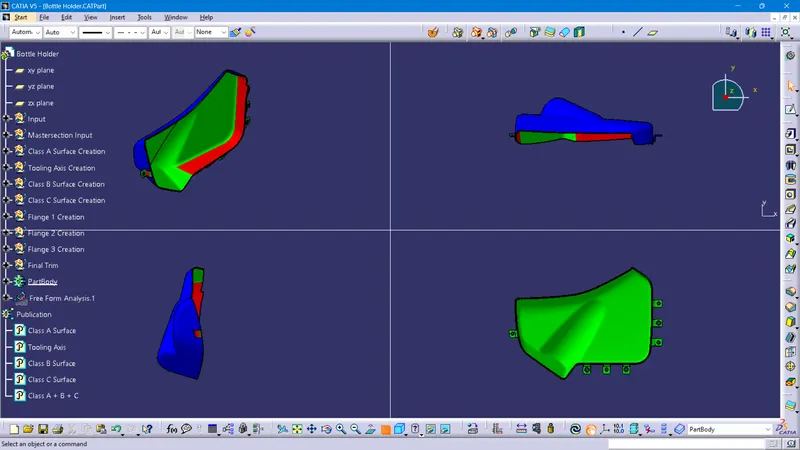
Analysis shows the drafted walls of the Armrest, Lower Substrate, Map Pocket, and Bottle Holder are above 3 degrees which is permissible for manufacturing in injection molding
Performed draft analysis for Armrest, Lower Substrate, Map Pocket, and Bottle Holder with 0.48deg
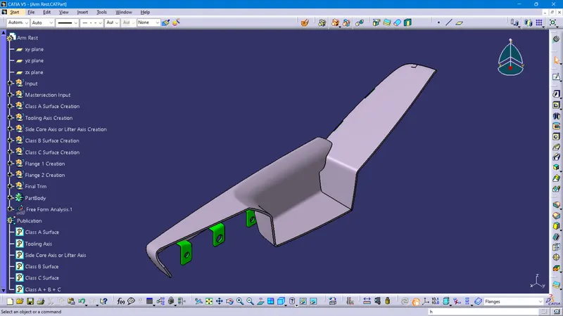
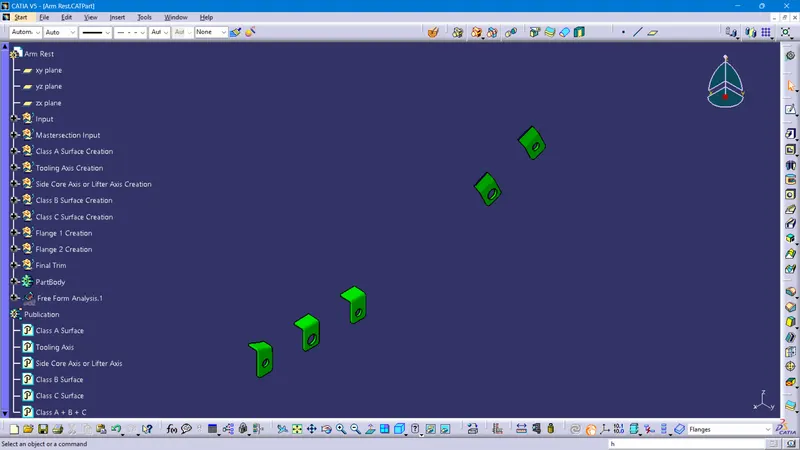
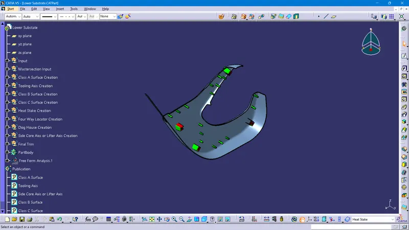
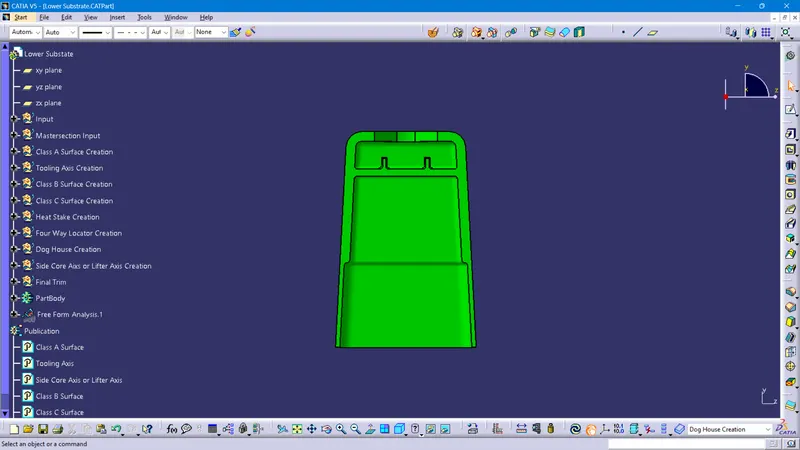
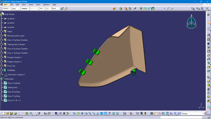
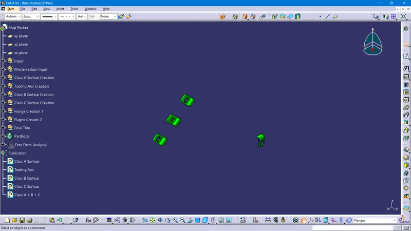
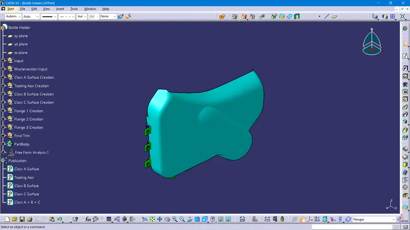
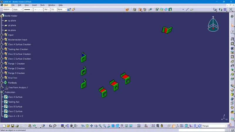
Analysis shows the drafted walls of the Armrest, Lower Substrate, Map Pocket, and Bottle Holder are 0.48 degrees which are permissible for manufacturing in injection molding
Conclusion
- Successfully created Side Door trim Panel plastic component.
- Successfully performed draft analysis for Class A surface and solid close surface.
- Successfully Extracted closed solid body from the plastic surface.
- Created the Heat stakes and locators in the Door Trim Lower substrate considering the design rules.
- Created the Dog house in the Door Trim Lower substrate considering the design rules.
- Created flanges in Arm Rest, Map Pocket, and Bottle Holder.
- Successfully performed final draft analysis for solid close surface with engineering features.