Week 12- Final project
FINAL PROJECT - DOOR TRIM PANEL DEVELOPMENT
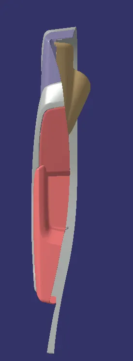
For the final assessment, door trim panel is to be developed with given surfaces and master sections. Using this as reference, other engineering features and attachment strategies are to be developed.
Before going to dive into design part, we have to reorder the tree to a structured format so as to ensure easy identification of parts. This is shown below:
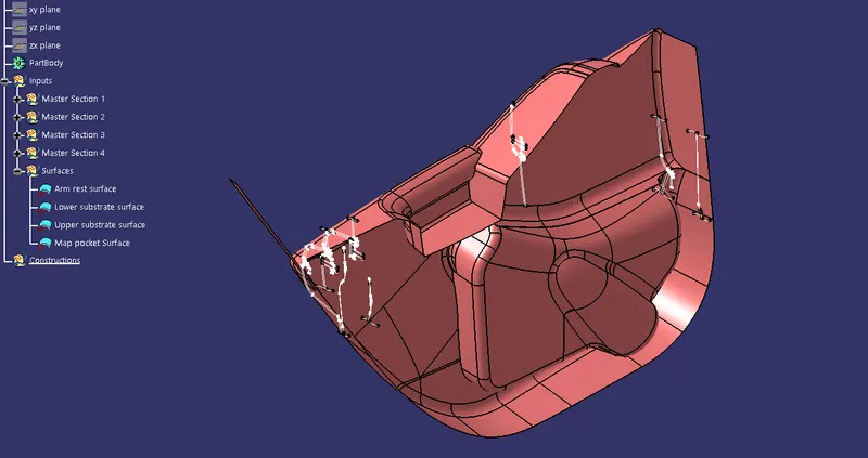
There are 4 parts here.
- Lower substrate
- Upper substrate
- Map pocket
They are to be developed as separate parts and rejoined to obtain final product. Each part development follows a structured flow, or an algorithm. First we need to take class A surface from the given surfaces for each part. Then using this, class B, class C, closed surface, solid model ...etc are to be developed. Draft analysis of parts should also be done.
1. LOWER SUBSTRATE
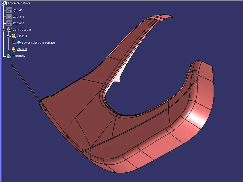
- CLASS A SURFACE
The Class A surface for lower substrate is obtained from the given CAD file. The surface is checked for any irregularities or flaws. It was found good for further proceedings.
- DRAFT ANALYSIS OF CLASS A
For draft analysis, first tooling axis is to be made. An arbitratry point is taken on the surface, and tooling axis is made normal to the surface in the global 'Y' direction. This method is followed because as per the geometry of lower substrate, the surface should clear draft analysis in normal direction. The draft analysis result is as follows:
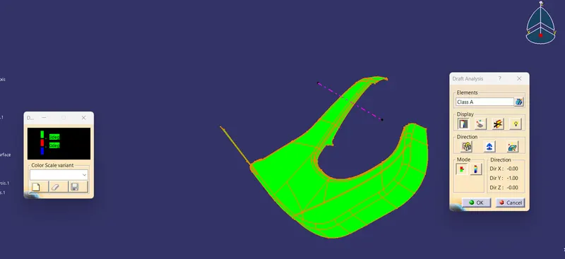
Each and every corner is clearing 3 degree draft for class A.
- CLASS B AND CLASS C SURFACE CREATION
Class B and Class C surfaces are created using the class A surface. For Class B, the class A surface is offsetted to 2.5mm (value got from master section). The surface should be checked for irregularities. Class B Surface so obtained is as follows:
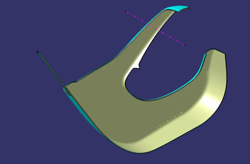
The surface in cyient colour is class A and that in yellow is class B.
For Class C surface creation, the boundary of class A is extracted. With reference to class A, the boundary is swept at 90 degrees to class A.
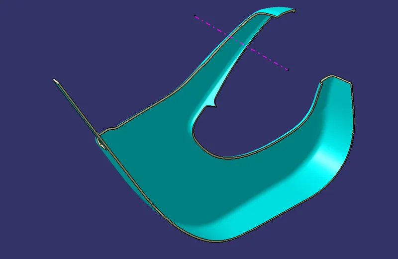
Figure shows class A in cyient coloyr and class C in yellow colour.
- CLOSED SURFACE AND SOLID BODY CREATION
For obtaining a closed surface, first class A and class C surfaces are joined together. Now this is trimmed with class B surface to obtain the final closed surface. In the part workbench, using closed surface tool, solid body of the the lower substrate is created.
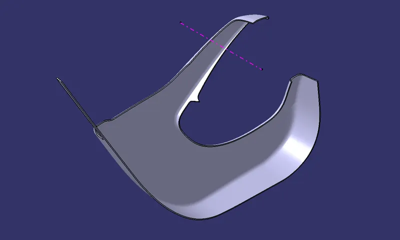
The solid body is shown above.
- DRAFT ANALYSIS OF SOLID BODY
Draft analysis of solid body is done with respect to tooling axis. The results obtained are satisfactory.
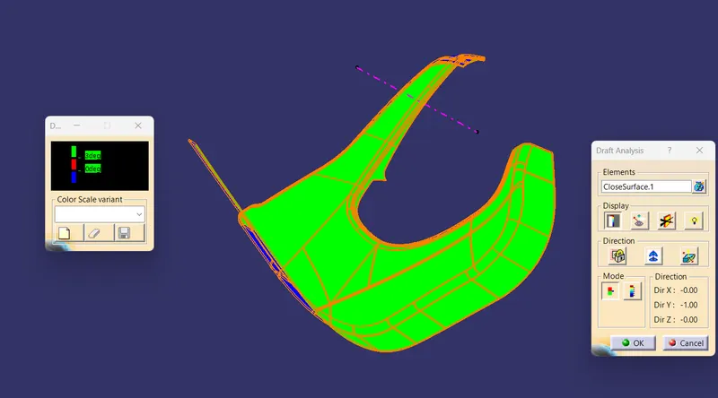
Now we have to design the engineering features on to this lower substrate.
- ENGINEERING FEATURES CREATION
From the reference and problem description, Lower substrate consists of heat stakes/ locators and dog house for pushpin. Heat stakes are made using master sectio as reference. From the master section, dimension of circles for heat stakes was found to be 4.5mm and 7.5mm. They are padded and ribs are added to avoid sink marks. Heat stakes are modeled as follows:
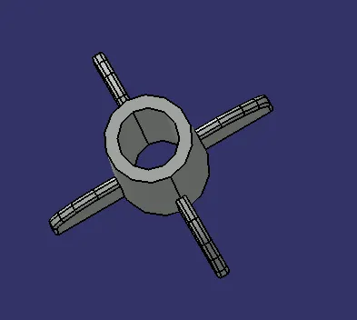
A total of 10 heat stakes were provided in lower substrate.
Dog house design is done purely based on engineering principles, with a height of 30mm. The cut in the lower portion were also modeled as per principles. Adequate drafts and fillets were provided for the dog house. The purpose of this dog house is to hold the push clip. Push clip model was given. Thus a dog house- push clip assembly was created as follows:
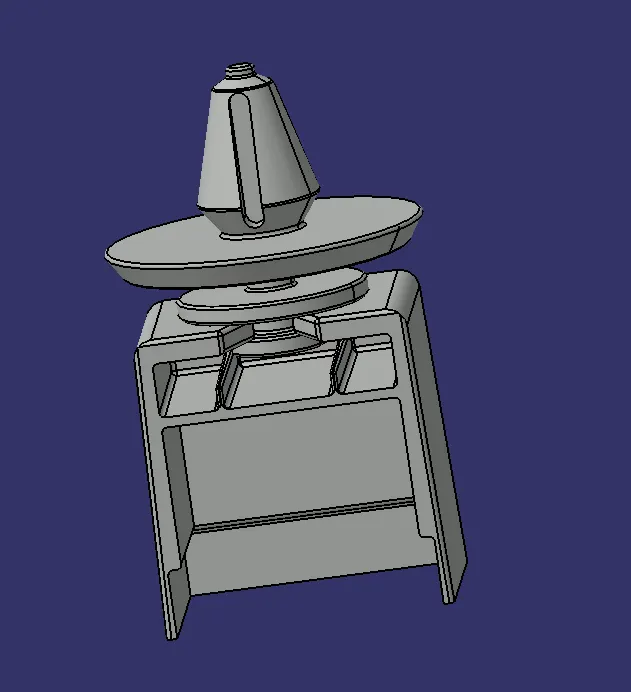
3 dog house-push clip assembly and heat stakes were added to lower substrate to obtain the final output as follows:
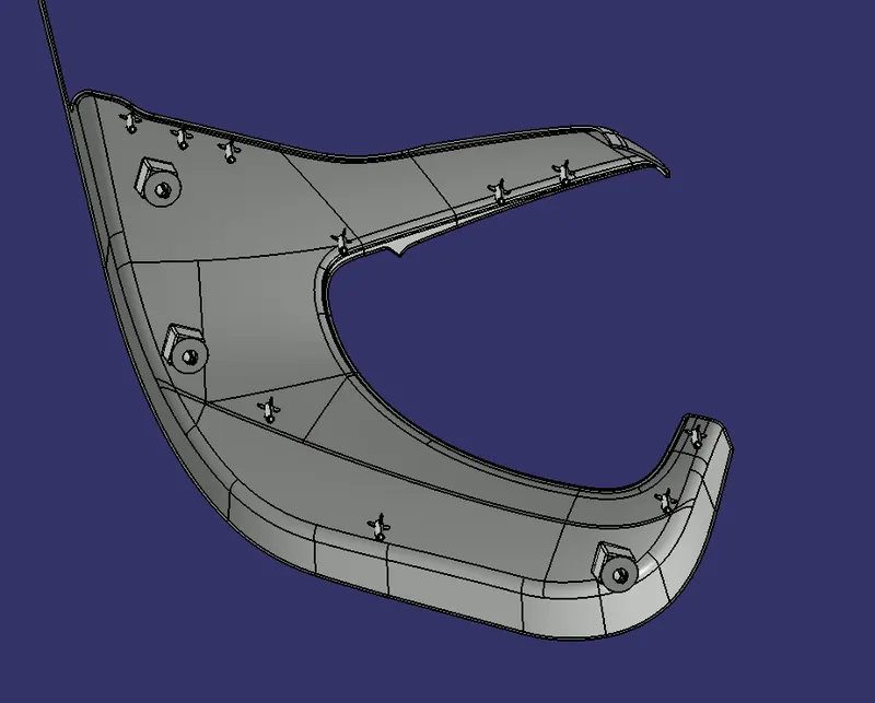
2. UPPER SUBSTRATE
The construction of upper substrate is similar to that of lower substrate.
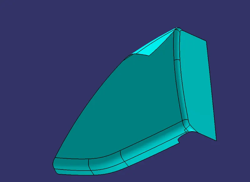
- CLASS A SURFACE
The Class A surface for lower substrate is obtained from the given CAD file. The surface is checked for any irregularities or flaws. It was found good for further proceedings.
- DRAFT ANALYSIS OF CLASS A
For draft analysis, first tooling axis is to be made. An arbitratry point is taken on the surface, and tooling axis is made normal to the surface in the global 'Y' direction. The draft analysis result is as follows:

The results obtained are good and we can proceed with further design of class B and C surfaces.
- CLASS B AND CLASS C SURFACE CREATION
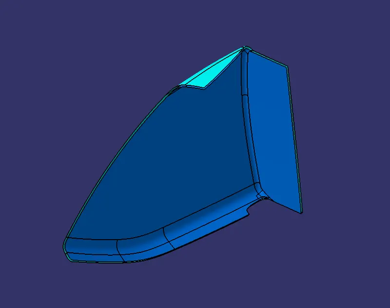
Class B and C surfaces are created using class A surface only. Class A surface is offsetted to 2.5mm to get class B surface. There will be some corrections to be done in the class B surface after offsetting from class A. These can be rectified by using multisection tool. The class A (cyient) and class B surface (blue) is shown below:
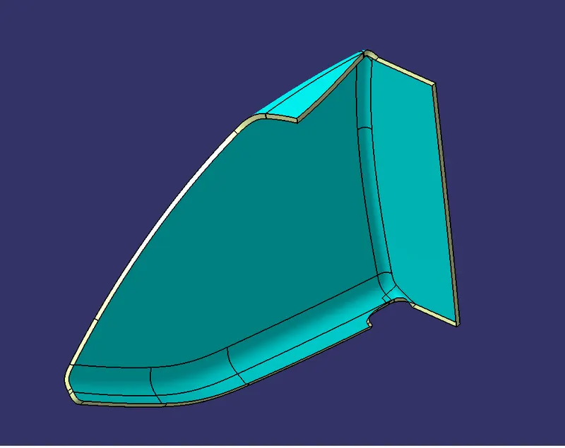
Class C surface joins class A and B and forms a closed surface body. The boundary of class A is extracted and is swept at right angle to the A surface, to obtain class C. Class C surface is shown in yellow colour below:
- CLOSED SURFACE, SOLID BODY CREATION AND DRAFT ANALYSIS OF SOLID BODY
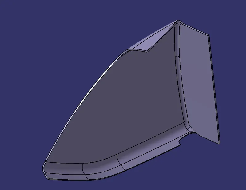
Once the creation of B and C surfaces are over, they have to be joined to form a closed surface body. For that, first A and C surfaces are joined and later this assembly is trimmed to form the closed surface. Using the closed surface tool in part workbench, a solid body created out of it. This will serve as our main body for upper substrate. The solid body is shown below:
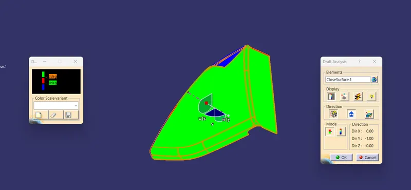
After creating the main body, draft analysis is to be done in order to ensure smooth ejection of the part from core. The analysis is carried out using the tooling axis created for draft analysis of class A surface. The results obtained are satisfactory and is given below:
- ENGINEERING FEATURE CREATION
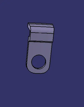
Flanges are required for upper substrate, in order to get assembled with lower substrate, as per master section given. The flanges are created using master sections as references. Typical flange for upper substrate is as follows:
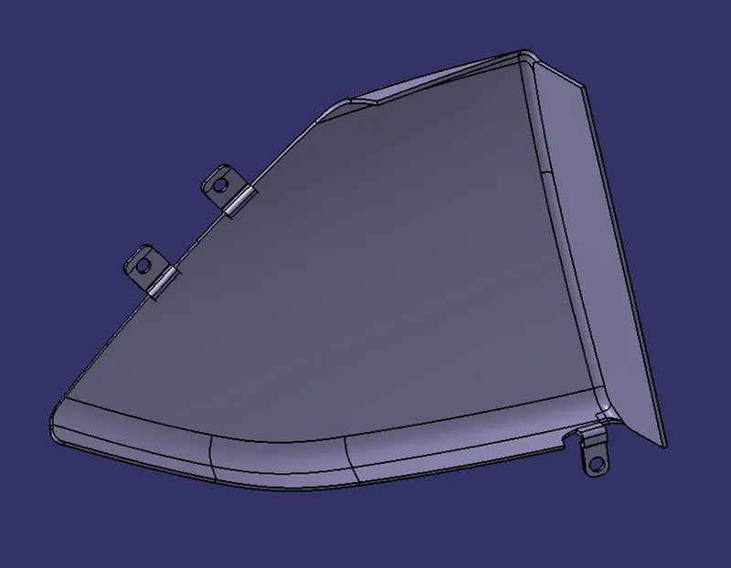
A total of 3 flanges are created and they are trimmed with main body to obtain final Upper substrate body as follows:
3. MAP POCKET
- CLASS A SURFACE & DRAFT ANALYSIS
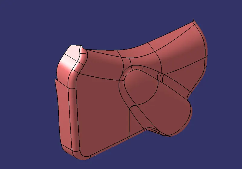
From the input CAD file, the class A surface for map pocket is taken and pasted on new part for construction. The surface has no flaws/ irregularities. So we can proceed with further designing. Class A surface for Map Pocket is shown below:
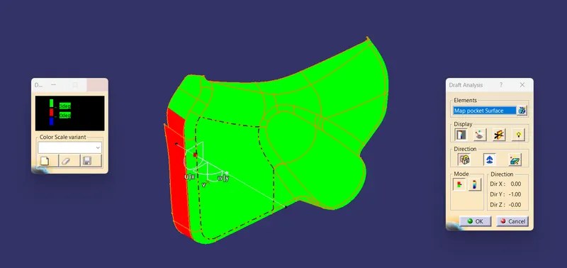
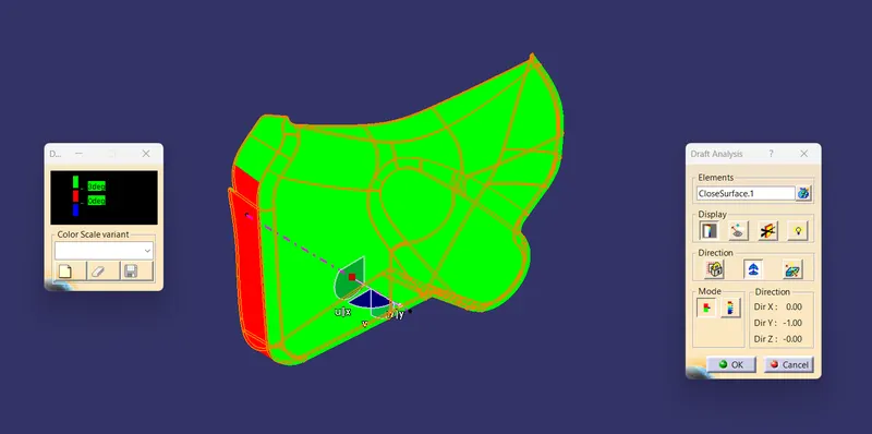
Now, before moving to further steps, draft analysis needs to be carried out. For that tooling axis is made in the normal direction with respect to the flat face on class A surface (in global Y axis). Every point except the side walls cleared draft analysis with 3 degree draft angle. For side walls, it is 0 degree, which is to be addressed by class A designer.
- CLASS B AND C SURFACE CREATION
Class B and C surfaces are created using class A surfaces only. Class A is offsetted to 2.5 mm for obtaininf class B, where as boundary of class A is swept at right angle to obtain class C surface.
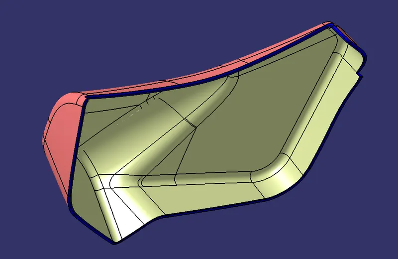
Figure shows class A in pink colour, class B in yellow colour and class C in blue colour
- CLOSED SURFACE AND SOLID BODY CREATION
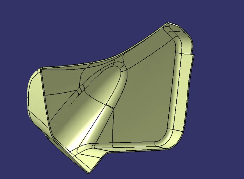
Class A and class C surfaces are joined and trimmed with class B surface to get the final closed surface body as depicted in the figure below:
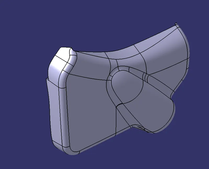
Now, a solid body is to be made out from this closed surface body. This can be done by using closed surface tool in part workbench. The final main body for map pocket is as given in the figure below:
- DRAFT ANALYSIS OF SOLID BODY
After creation of soild body, draft analysis of solid body is to be done. On analysis, the problematic area in the draft analysis of class A recurrs here as well. Except this part, every other point clears draft angle of 3 degree.
- ENGINEERING FEATURE CREATION
For Map pocket, with reference to the master section, flanges are required for aligning with locators/ heat stakes on lower substrate. Sketches are made with reference to master sections. Typical flange for Map pocket is as follows:
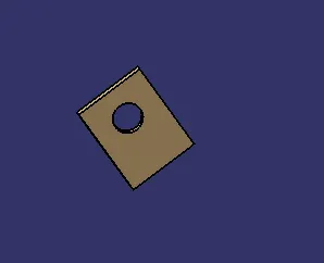
Later these are trimmed with main body to obtain final body for Map pocket. Essential fillets are provided to flanges:
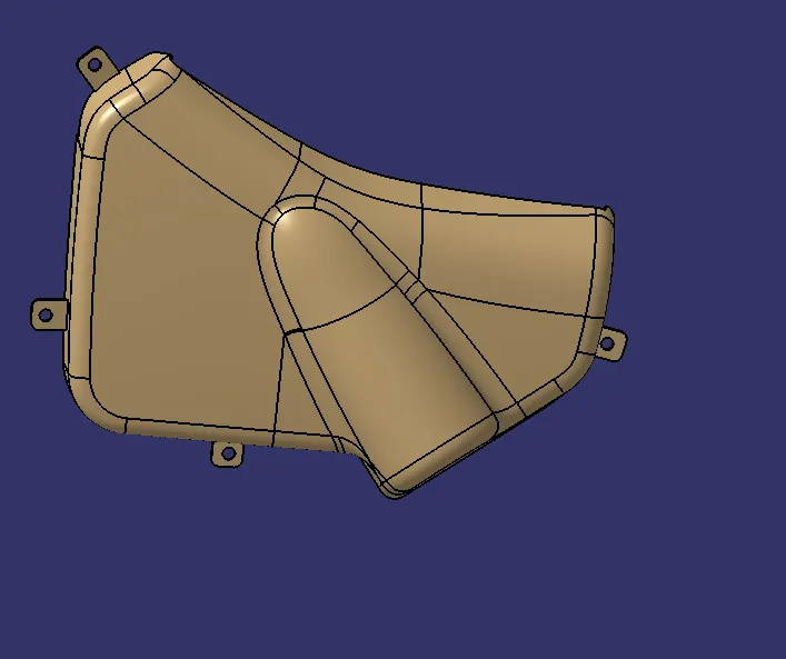
Thus final Map pocket body is obtained.
4. ARM REST
- CLASS A SURFACE & DRAFT ANALYSIS
The class A of Arm rest required some reworks before moving to further proceeedings due to some error with the surface. Some extractions and trims are done and some unwanted portions are deleted. The final class A used is as follows:
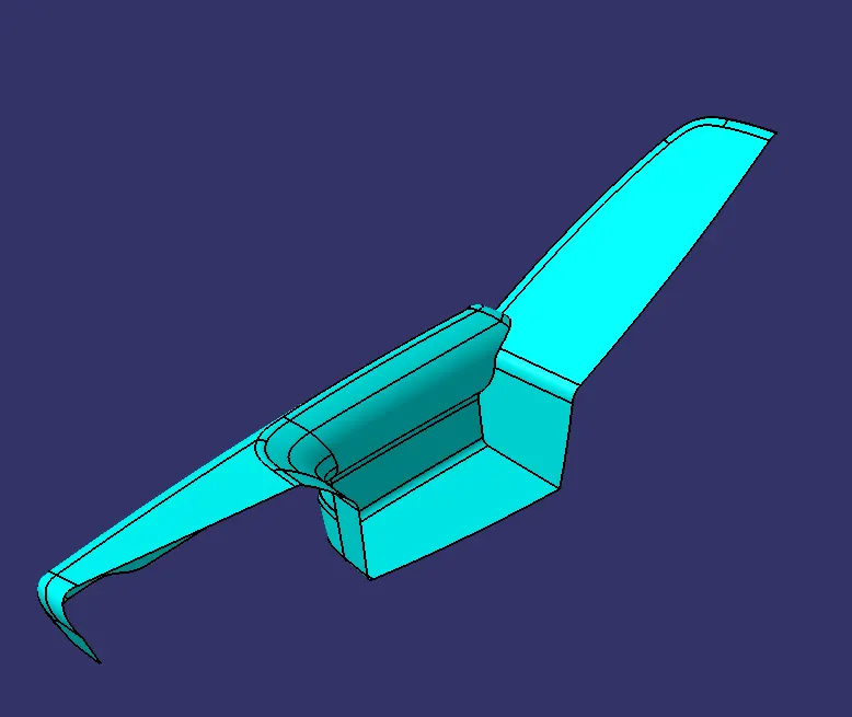
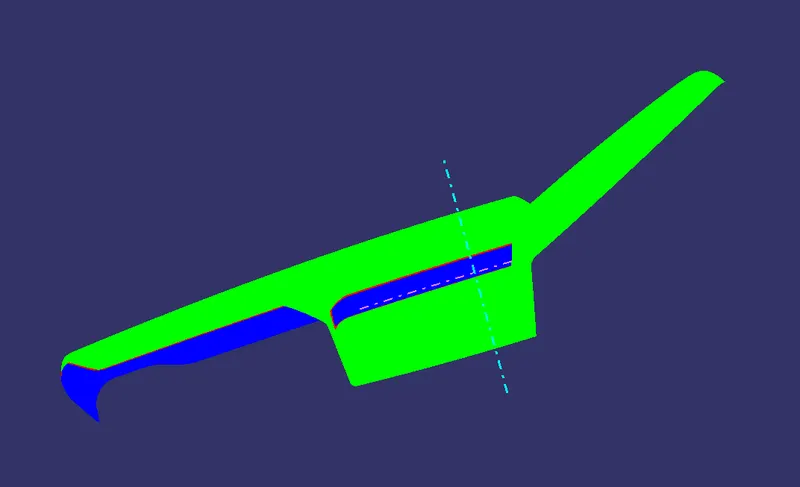
For the draft analysis, tooling axis was made in the normal direction to the surface. But on draft analysis, the side faces didnot clear minimum draft angle requirement. This problem is to be rectified by the class A designer. The figure below shows the result obtained:
- CLASS B AND C SURFACE CREATION
Unlike other geometries in this project, arm rest class B design is different. The given surface is of a cushioning surface, so we have to offset twice to get B surface. From the master section, it is clear that the B surfaces are at 2 mm and 4.5mm from the given surface. Offsetting this surface to respective lengths obtains our required B1 and B2 surfaces. Mutisection, trim, split etc were used for surface improvements. Class C surface is created by sweeping the boundaries of class B1 surface normal to it. The class B1, B2 and C surfaces are given below:
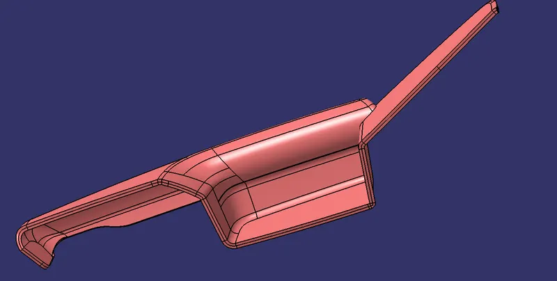
Top surface is the B1 surface, bottom is the B2 and the side is C surface.
- CLOSED SURFACE AND SOLID BODY CREATION
Class B1 and class C surfaces are joined and trimmed with class B2 surface to get the final closed surface body. Now, a solid body is to be made out from this closed surface body. This can be done by using closed surface tool in part workbench. The final main body for arm rest is as given in the figure below:
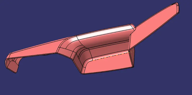
Now engineering features (flanges) are to be attached to this body.
NB: Draft analysis for main body not done because, it has flaws in the surface and will not clear with required draft angle.
- ENGINEERING FEATURE CREATION
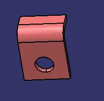
From the master section, it is clear that arm rest contains flanges which gets aligned with heat stakes/ locators in lower substrate. This is created using given master section. 3 flanges are created. The figure shows a flange for arm rest:
Later, these are assembled into a single body and trimmed with main body to obtain final Arm rest body. Adequate fillets are given.
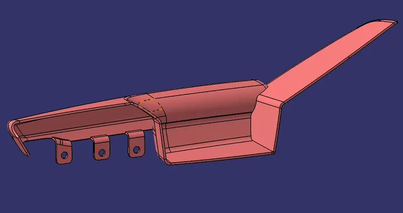
Figure shows final arm rest body.
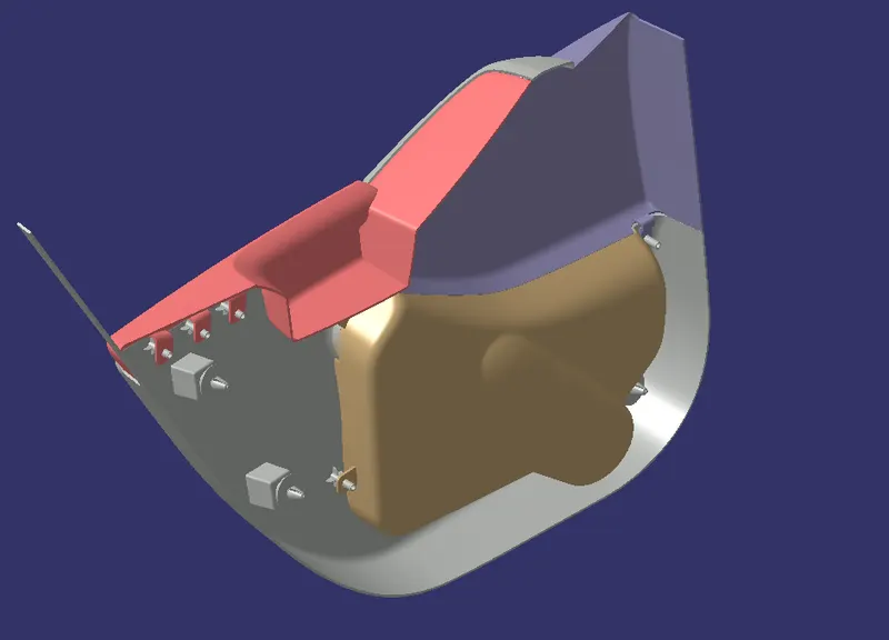
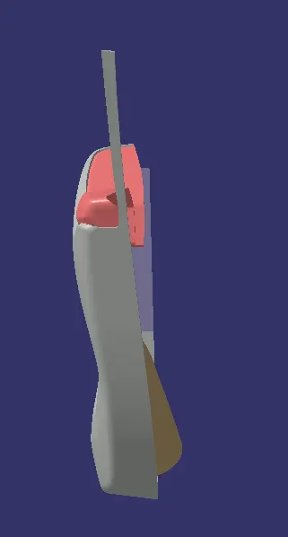
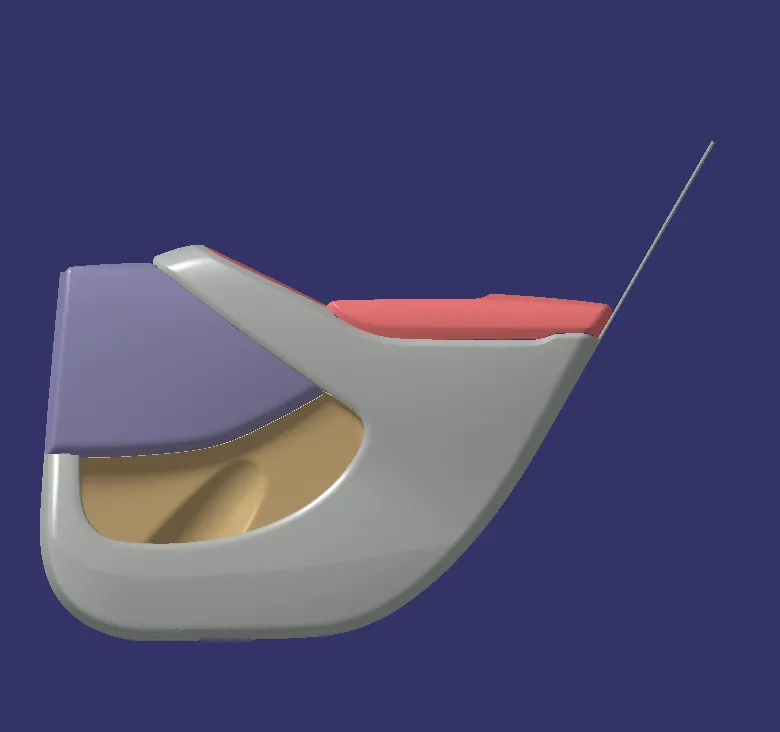
FINAL BODY- DOOR TRIM PANEL
Isometric View:
Front View:
Side View:
Top View: