Week 12- Final project
FINAL PROJECT DOOR TRIM PANEL
AIM
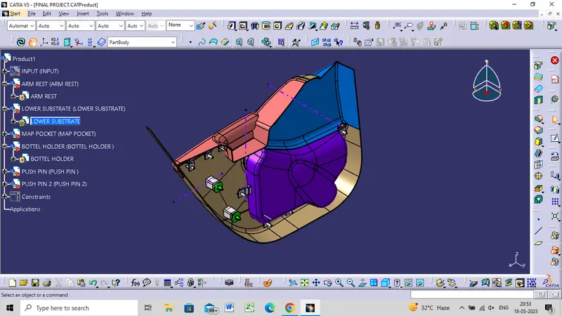
- To develop a Door Trim panel CAD model by considering the inputs given (ie., Class A surfaces,Master Sections) as like in OEM and Tier 1companies.
- Develop an attachment strategy for the complete Door Panel work by creating the B side features as per design guidelines.
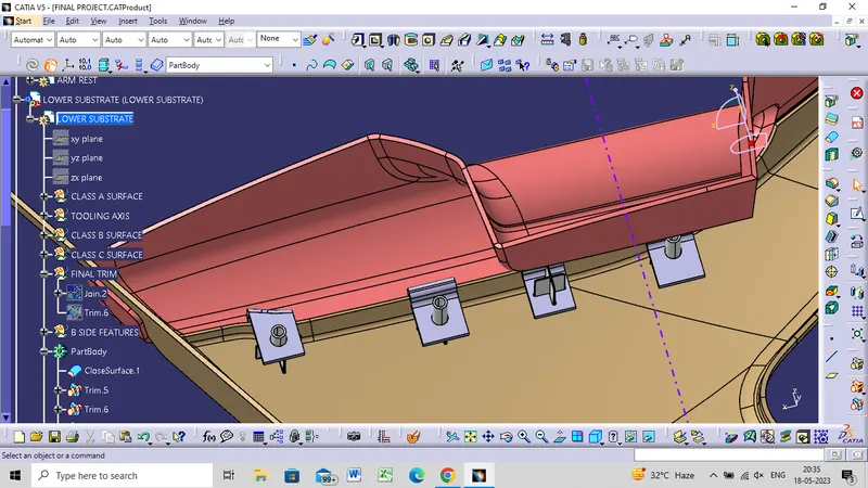
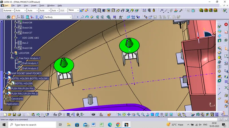
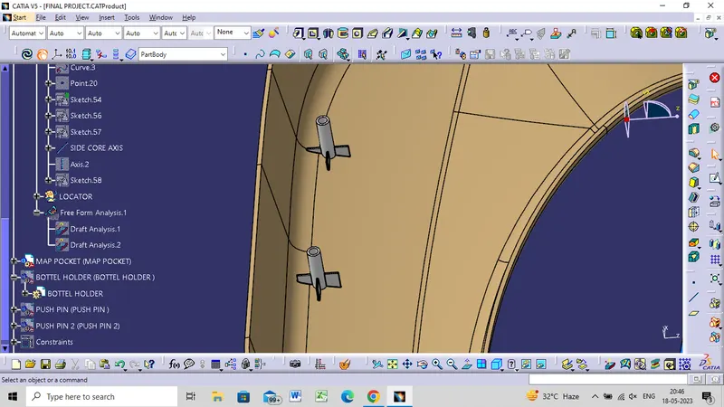
- Use Pushpin (given) with Dog House for attaching the Trim with the BiW part and Heat Stakes for part to part attachment.
TOOLING AXIS
- Tooling direction is created by manually adjusting the compass.
- Now extract any surface and create a mid-point on it.
- Then create a dummy axis creating a line on the point and direction along the y-axis.
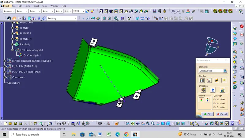
- Perform draft analysis to find whether the given axis clears the draft analysis. If not create a new tooling axis.
CLASS A SUFACE FOR ARM REST
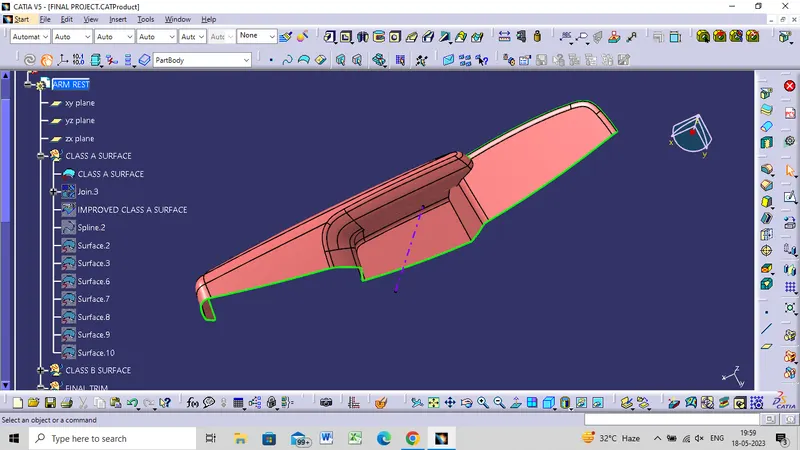
GIVEN CLASS A SURFACE
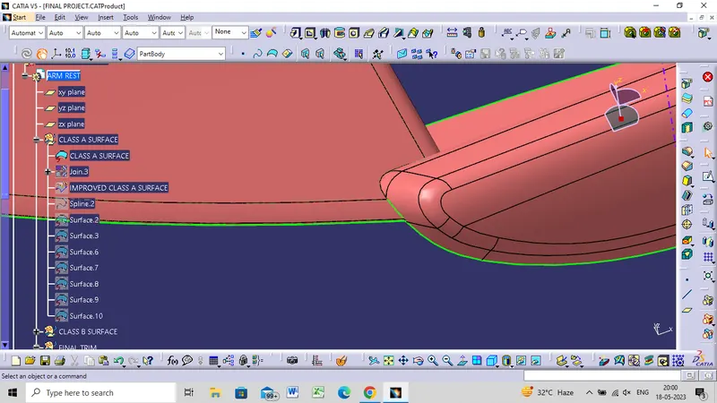
IMPROVED CLASS A SURFACE
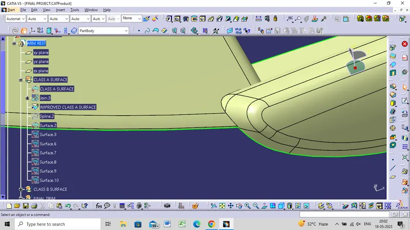
CLASS B SURFACE
- Create offset surface of CLASS-A about 2.5mm inward direction.
- Check for discontinuity and rework on the offset patch surface using extract, multi-extract.
- Join the surfaces and ensure the final CLASS-B surface created has no gaps.
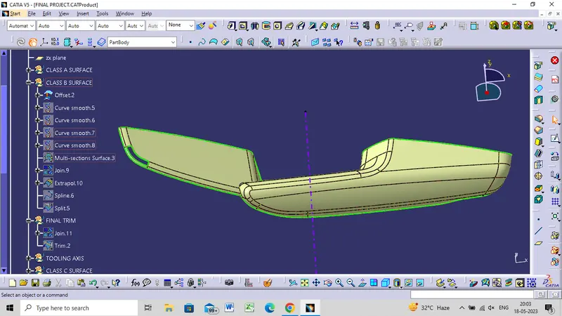
CLASS B SURFACE WITHOUT PATCH
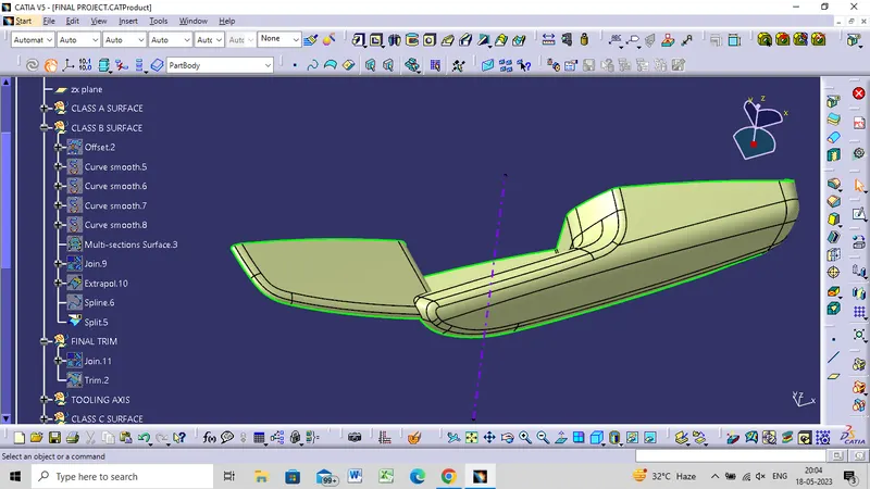
CLASS C SURFACE
- Create the sweep to the surface and tooling axis multi-extracting the CLASS-A boundary.
- Join the sweep surfaces by using commands like extrapolate, rmulti-sectiontion surface.
- Finally join all the sweep surfaces and ensure the continuity of the CLASS-C surface.
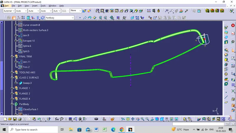
CLOSE BODY
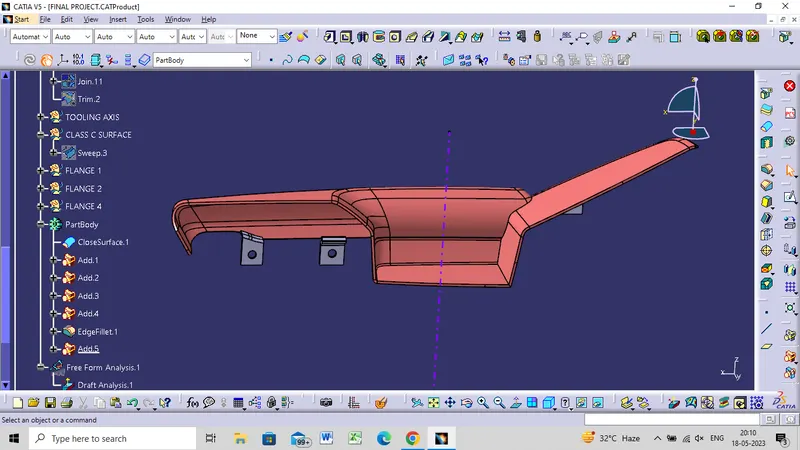
DRAFT ANALYSIS
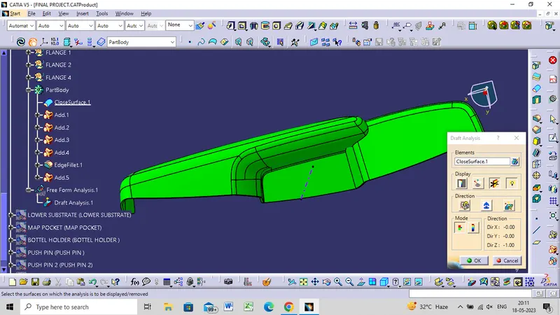
LOWER SUBSTRATE
CLASS A SURFACE
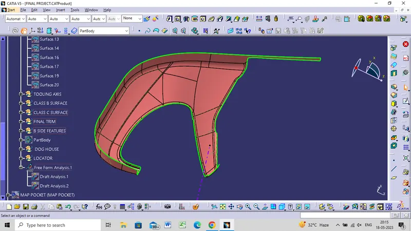
CLASS B SURFACE
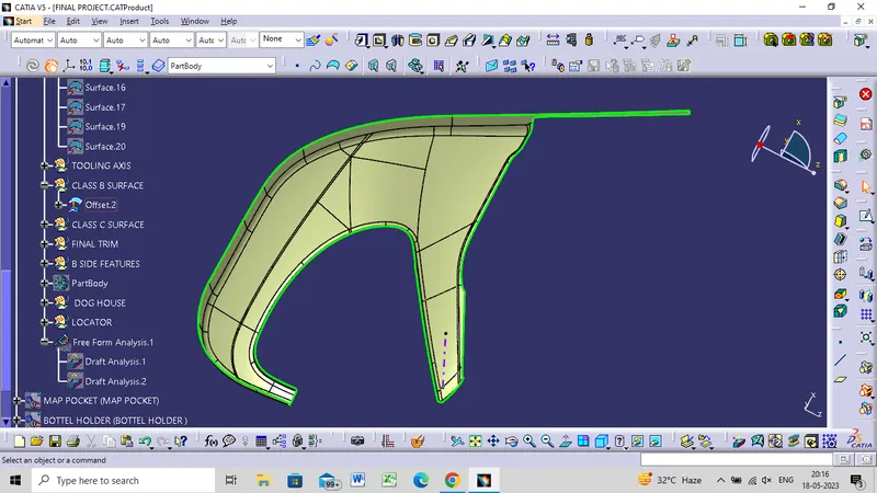
CLASS C SURFACE
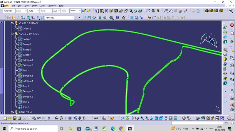
FINAL JOIN
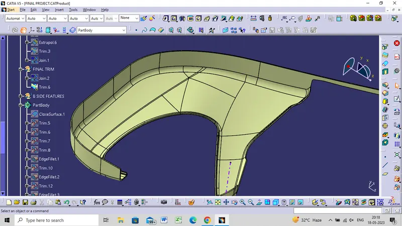
DRAFT ANALYSIS
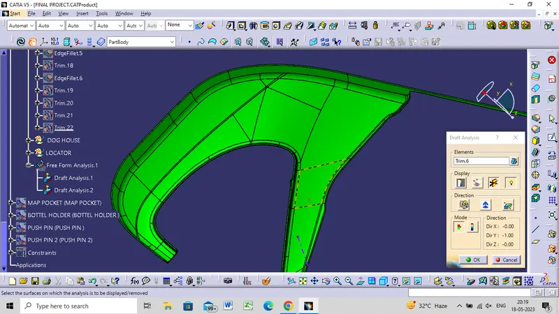
MAP POCKET
CLASS A SURFACE
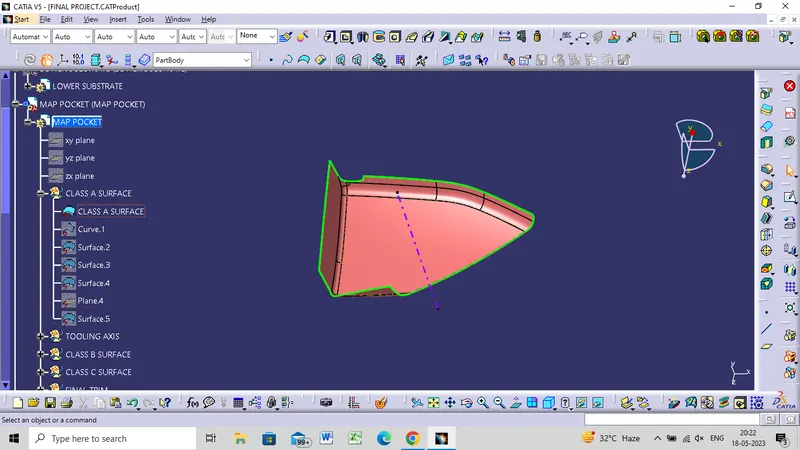
CLASS B SURFACE WITHOUT PATCH
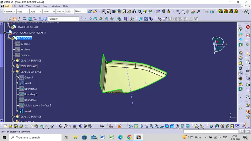
CLASS C SURFACE
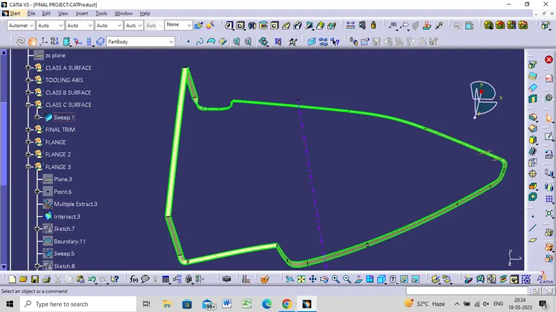
CLOSE BODY
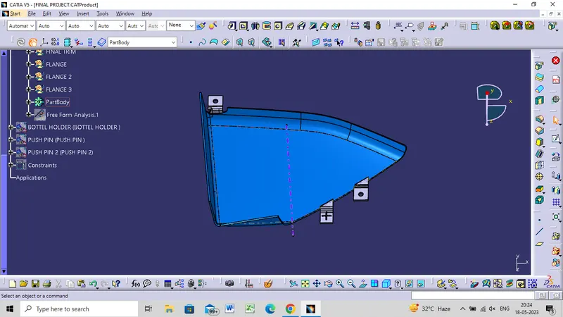
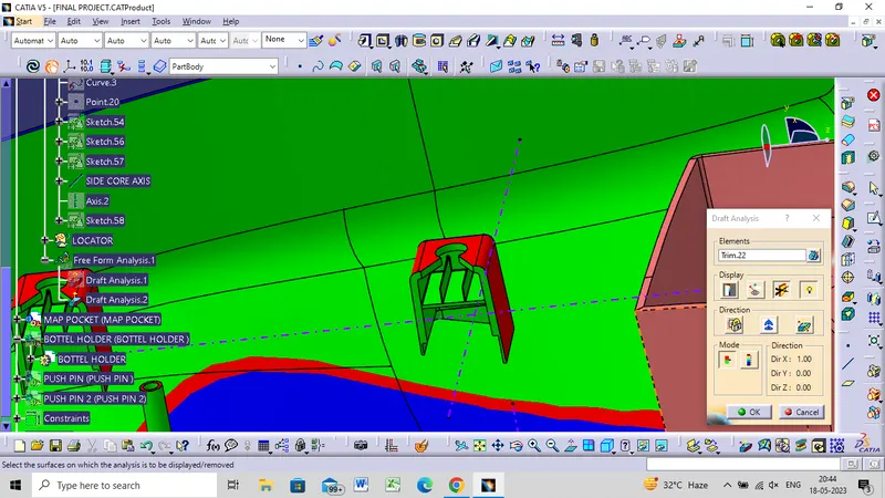
DRAFT ANALYSIS
BOTTLE HOLDER
CLASS A SURFACE
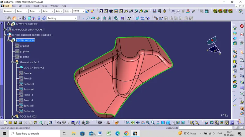
CLASS B SURFACE
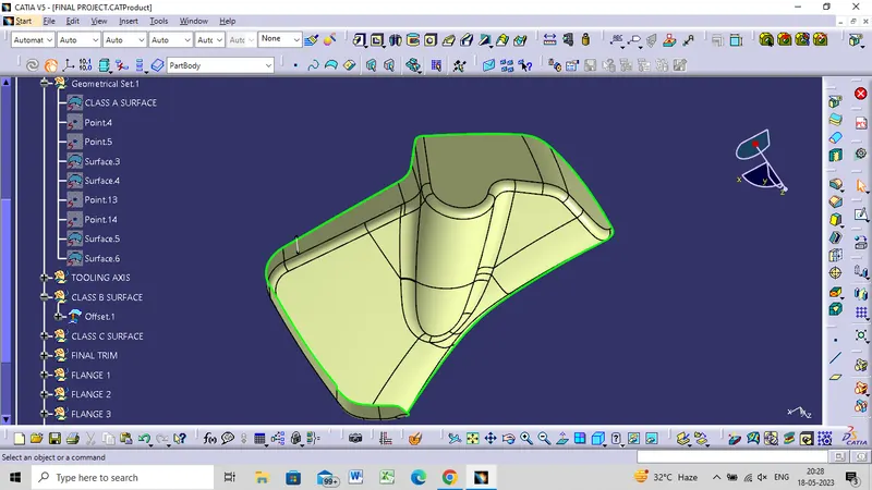
CLASS C SURFACE
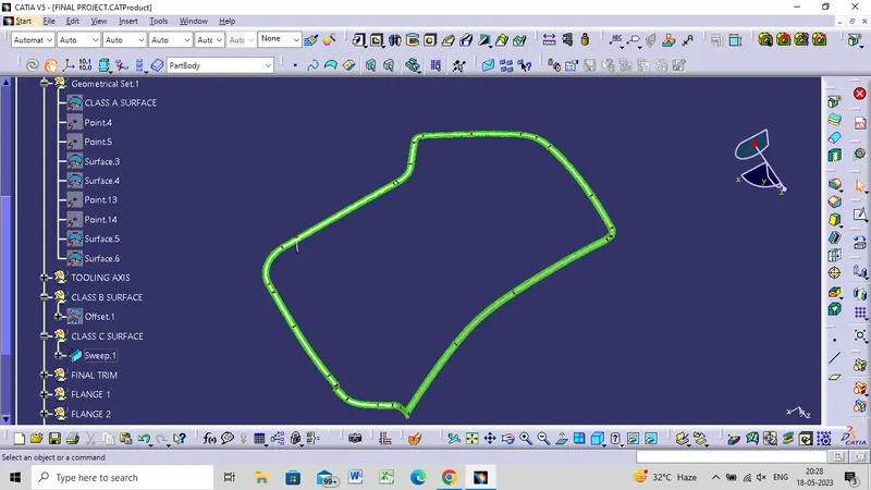
CLOSE BODY
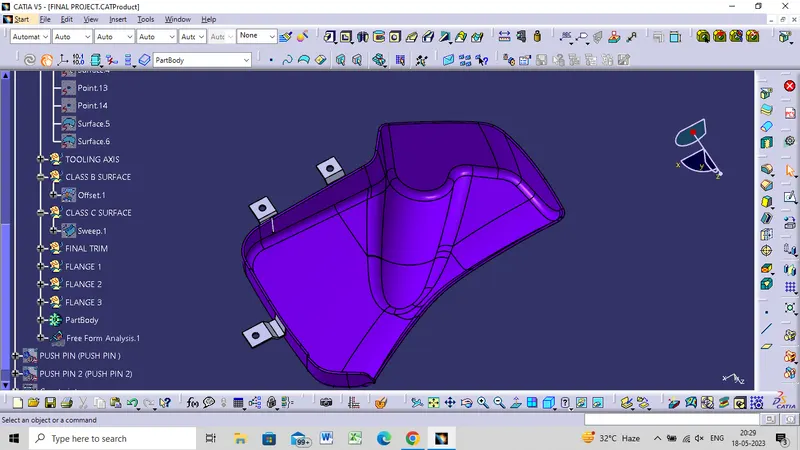
FLANGES CREATIONS
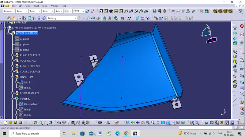
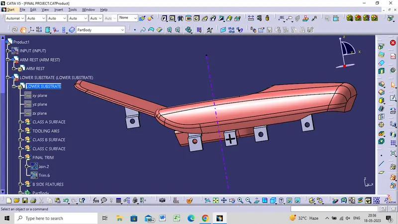
- In order to Join the Bottle Holder with the other bodies, I created 3 Flanges separately with counter holes, Flanges are different based on the engineering features that will be held.
- Then these flanges are assembled to the main body (Bottle Holder) by an un-trim feature.
- Each Flange was created by extracting the surface from Class C Surface added by Generative Surface.
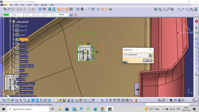
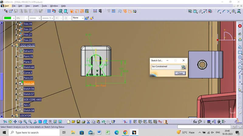
- Then I applied the close surface feature to create the flange body, Drafted by 0.5 deg, Filleted. Also, it is important to mention that the counter holes were created by iso-constrained, positioned sketches and then padded and drafted before it was removed from the main flange.
 \
\
ENGINEERING FEATURE CREATION
DOG HOUSE CREATION
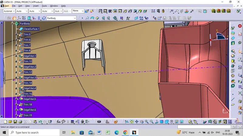
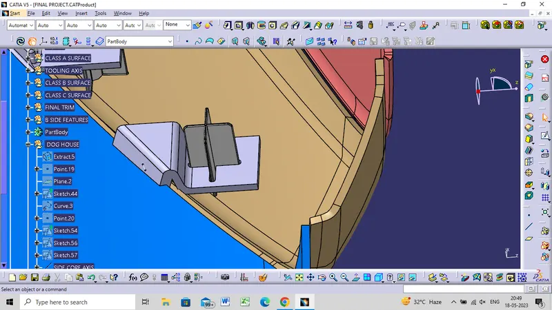
- The dog house is an engineering feature used in the plastic trim design.
- Dog houses are used as supporting features. Sometimes other engineering features like snaps; locators, etc. are mounded on them to increase their strength.
- The dog house is mostly used in automotive plastic and its main purpose is to help to avoid sink marks.
ISO CONSTRAINED
PUSH PIN
DRAFT ANALYSIS FOR DOG HOUSE
HEAT STAKE CREATION
LOCATOR
FRONT VIEW
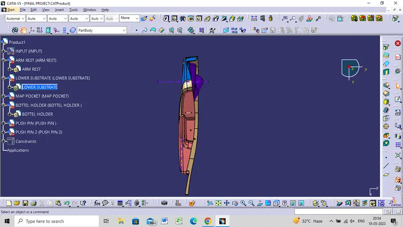
TOP VIEW
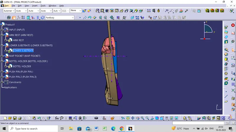
SIDE VIEW
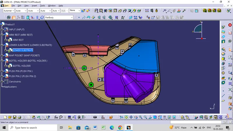
ISOMETIC VIEW