Week 12- Final project
PLASTIC DESIGN - DOOR TRIM PANEL,
Aim:
To create a CAD model as per OEM standards from the below inputs,
- Class A surface
- Nominal thickness : Master sections
- Attachment strategy
Software Used: Catia V5.
STEPS TO BE FOLLOWED :
- To create individual tooling axis for the parts and perform draft analysis on the class A surface.
- To create the class B and class C surfaces from the given class A surface.
- To form a solid geometry by combining all the surfaces.
- To decide an attachment strategy for the part and create engineering features in reference from the master section provided.
- To perform draft analysis on the solid part model with all engineering features.
- To assemble all the components togehter to obtain the final trim.
Input Given Data: 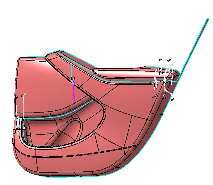 Input of Class A surface and Master section: BACK SIDE:
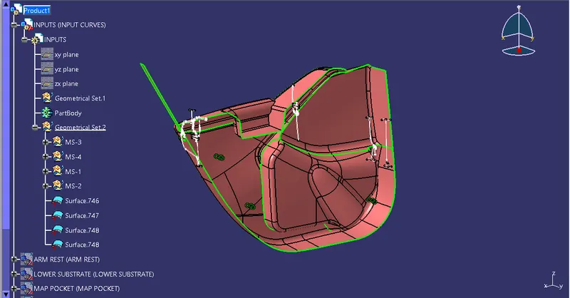
FRONT SIDE:
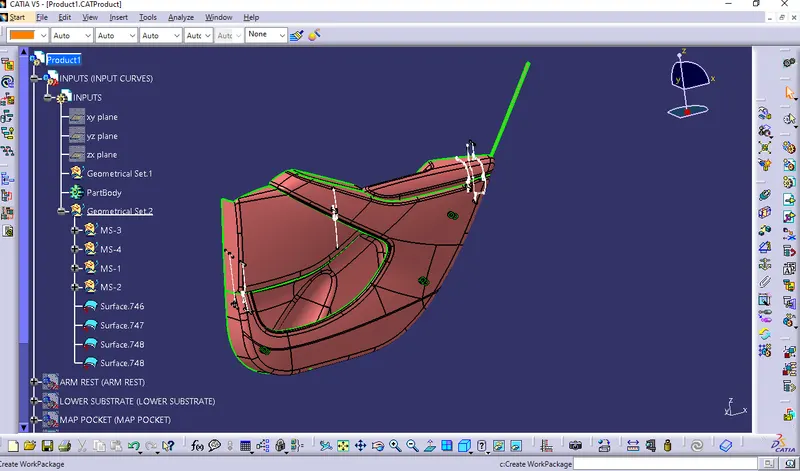
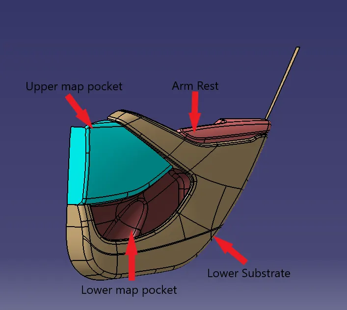 Note: Lower Map pocket is Bottle Holder.
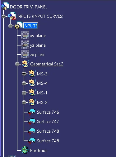
- First segregate the master sections and then copy the surfaces from product file to individual part files.
- Now work on the bodies individually to make them as closed surfaces and then into solid bodies.
Introduction:
As per automotive industrial standards to achieve perfect and asthetic shape of door trim or any plastic components base product design perfection is must. Few important neccessory skils as below,
- As a Interior/Exterior Product designer should be aware about the parting surface, parting line, core and cavity know-how is one of the key skill.
- Our design should be manufacturable
- Our design can be easy for assembly,
- And our design should be serviceability.
The door panel is the interference between the interior of the car and the inner workings of the door. Generally, the door panel is divided into two parts of easy designing like arm rest, map pocket, lower substrate, bottle holder, these requires one of the toughest requirements among the interior parts of the car. This should be designed to with stand the load while being less than 2mm in the thickness and also protect the occupants during collisions. Door currently has an inner full width panel consisting of electronic windows. Central locking system and speakers. These panels typically consist of a covered with either textiles or plastics. 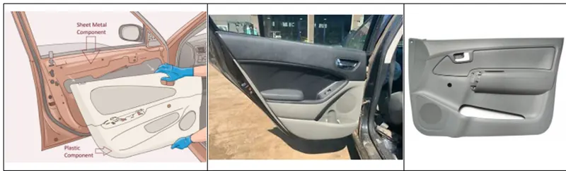 The below views for the reference of the door panel mounting portion.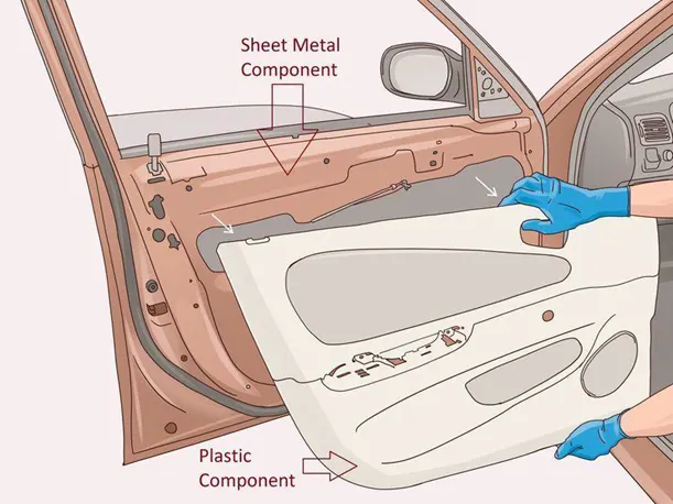
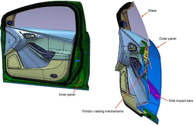
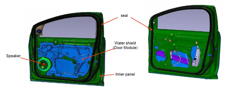 The following material using for trim mfg under thermoplastic materials.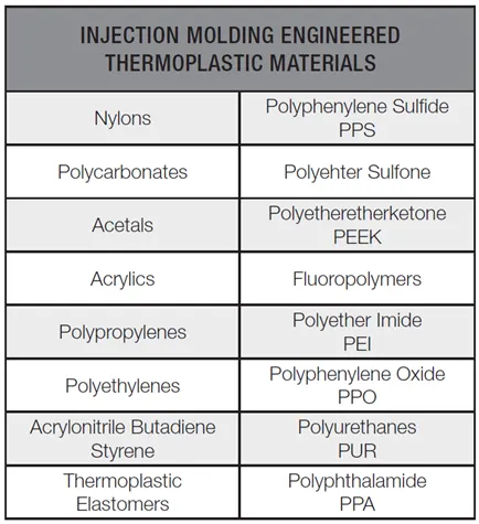
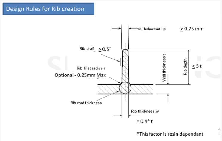
Design rules followed,
Synopsis of the project
In this project we are planning to make the following targets,
- Create thickened part using master section for reference
- Create the mounting features as per design guidelines in the industry and with master sections
- Apply material details :
- Draft analysis & Tooling analysis
- Creation of parting lines and check tooling feasibility.
We have followed below steps to achieve the above outcomes.
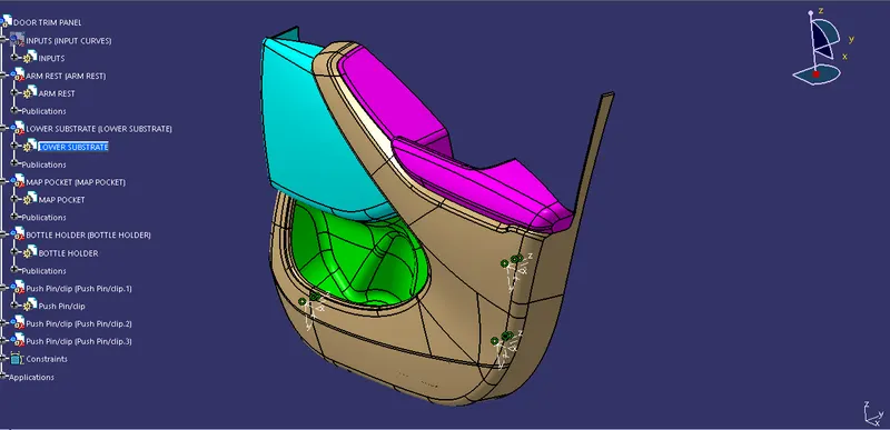
Herewith I have showcase the final view outcome view for reference.
Final Body Images with plastic material mode applied is below: 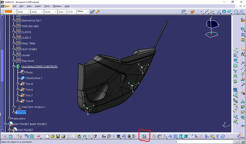
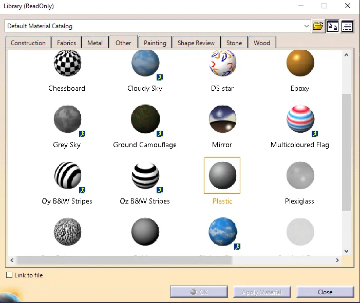
 The above image is material mode render view.
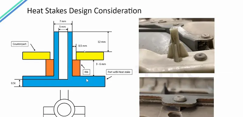
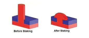
There is 4 different class A surface provided as a input and we got heatstake before & after view, Flange & component thickness from the provided master section.
The following component we got worked out,
- ARM REST
- LOWER SUBSTRATE
- MAP POCKET
- BOTTLE HOLDER
Here we started to work from Arm Rest.
DOOR ARM REST:
An arm rest offers the possibility of comfortably positioning your hand when driving on a motorway or standing in traffic, yet not only. Depending on the equipment of an individual vehicle, it can also combine the functions of the control console of the vehicle’s electrical systems and the practical storage compartment. Car armrests are manufactured from a variety of materials, including a hard plastic base, a soft foam top, and an outer pad. All these components should provide comfort of use, durability, stability and safety.
Class-A Surface :-
In automotive design, a class A surface is any of a set of free form surfaces of high efficiency and quality. It gives the aesthetic of the component which is created by the styling team and gives to the part design engineer to create the part with all engineering aspects.
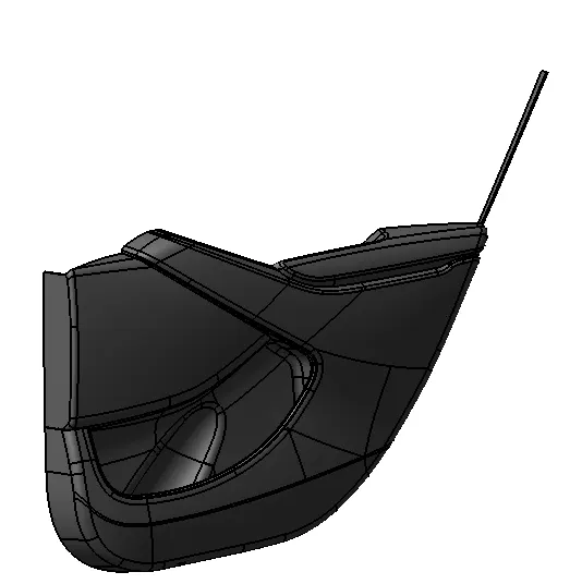
provided class A Picture as below,
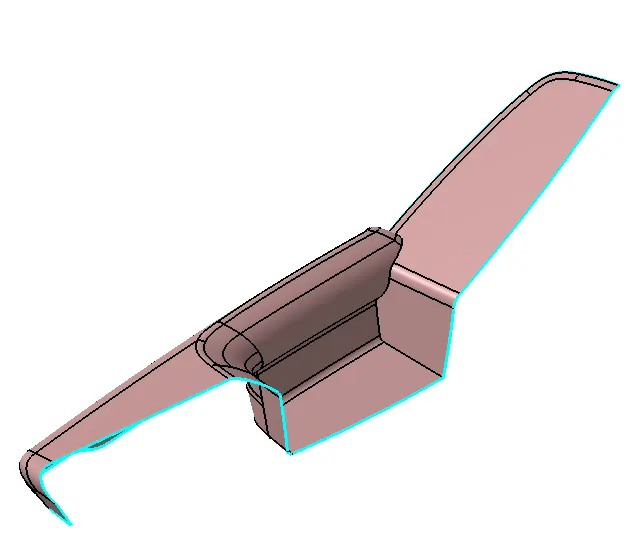 I got found error on the below highlighted portion on class A.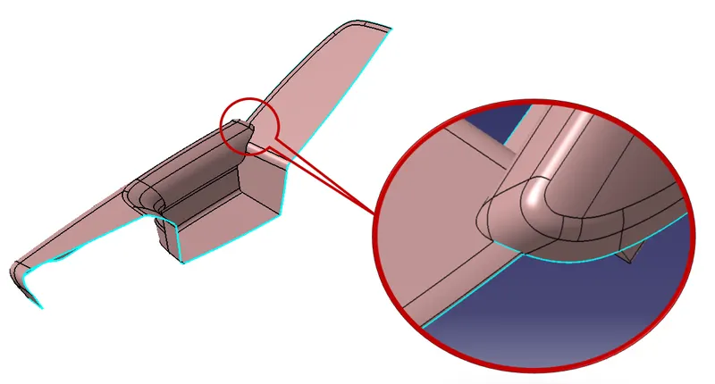
So at first I did improvement on Class A of arm rest on the specified portion which shows on above image.
Here below the image of Improved Class A of arm rest which I did with support of surface design operation tools.
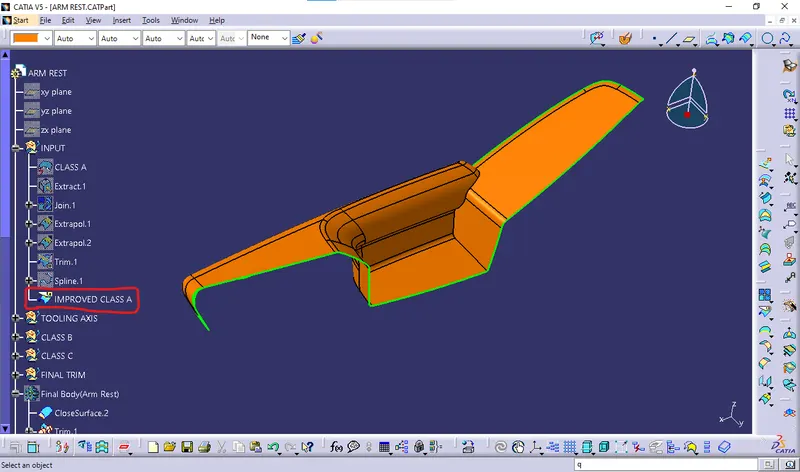
From the input of our improved Class A surface, i had started to work in order to focus of closed solid body creation.
To create solid body of arm rest we have to do following process,
- Tooling axis creation
- Draft analysis
- Class B creation
- Class C Creation
- Final closed body creation.
- Closed surface thicken by solid.
- Draft analysis for solid part
- Parting line creation & tooling feasbility check
- Engineering feature creation.
- Material addition.
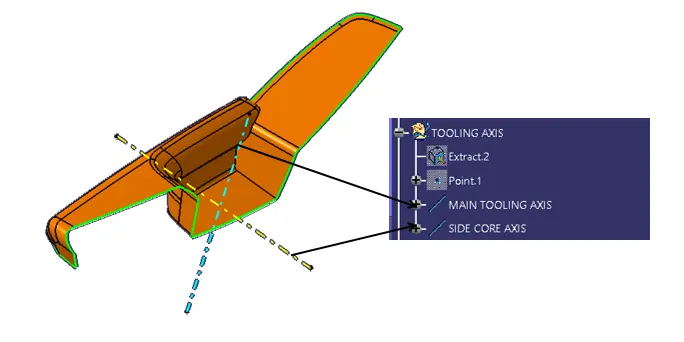
1. Tooling axis creation:
Tooling axis represents the opening and closing of the mold core and cavity during the manufacturing of the components. A plastic product designer should consider the best tooling direction to cutdown the cost of the component very less.
Method opted for creating tooling axis for the ARM REST
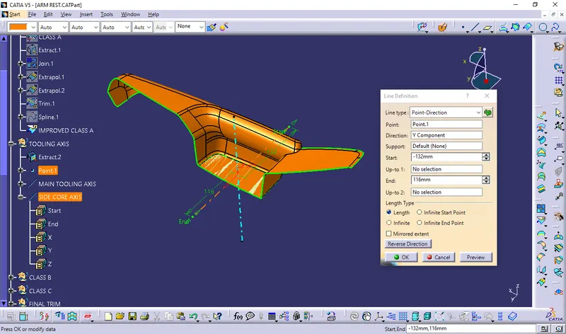
- Step 1: Insert a geometrical set . Extract the base surface and create a point at its center using point on surface option from point tool. Look for suitable axis to create a tooling axis so that all faces clear tooling .
- Step 2: Create an axis system without current option ticked at the above point. Create a position sketch with zy plane from axis system and above point as reference point.
- Step 3: Use intersect 3d objects option from project tool to create 2 lines by selecting a suitable plane(zy). Now create 2 lines which coincide with lines on both sides of the projection point . Create a line using bisect option .Allign the line in required axis direction.This is our Y tooling axis .
- Step 4: To create tooling axis about x direction, create a position sketch with xz plane as reference plane and projection point as the first point we created . Use cut section tool and create an intersection using projection tool . Now create a line that coincides with this line .
- Step 5 : Draw a line from origin in horizontal direction and create and angle constraint of 5 degrees. Use bisect option to create a line between that above lines . This is out X tooling axis .
- Step 6 : Create a new line using bisect option between X tooling and Y tooling line . this is our required Tooling Axis , Name this as tooling axis and publish it .
2. Draft Analysis of Class A:
I did draft analysis of the by axis consideration bisecting method tooling axis.
The angle results almost cleared the test under minimum limits of drafting angle.
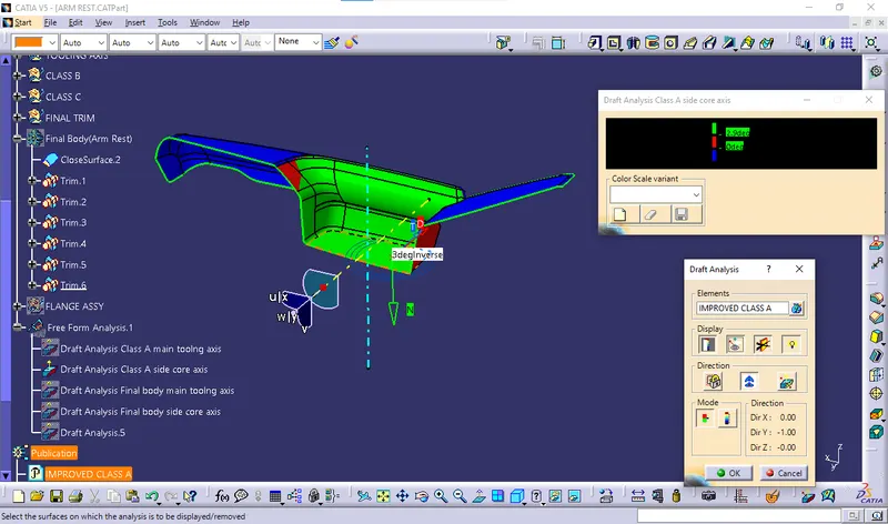
I got found some where below 3 dgree the below images color highlighted with angle limitation.
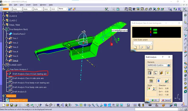
- SO the given class A surface cannot be cleared by the single tooling axis.
- Dog house is an engineering feature used in the plastic trim design.
- Dog houses are used as supporting features. Sometimes other engineering features like snaps; locators, etc. are mounded on them to increase their strength.
- Dog houses are designed to avoid SINK MARK created on the CLASS-B surface by screw bosses and to solve the length issues when giving screw bosses which need to be assembled to other components.
- Dog house is an engineering feature used in the plastic trim design.
- Dog houses are used as supporting features. Sometimes other engineering features like snaps; locators, etc. are mounded on them to increase their strength.
- Dog houses are designed to avoid SINK MARK created on the CLASS-B surface by screw bosses and to solve the length issues when giving screw bosses which need to be assembled to other components.
- Dog house is an engineering feature used in the plastic trim design.
- Dog houses are used as supporting features. Sometimes other engineering features like snaps; locators, etc. are mounded on them to increase their strength.
- Dog houses are designed to avoid SINK MARK created on the CLASS-B surface by screw bosses and to solve the length issues when giving screw bosses which need to be assembled to other components.
- so we take another tooling axis so as to clear the area which is not cleared by the main tooling axis.
3.Class B creation:
To create class B I did used Wireframe, Surface & Surface operation tools.
As much as possible way founded to simplify the process to create Class B Surface.
Below picture is reference view of arm rest class B,
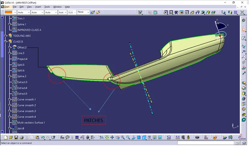
we offset the Class A surface and get the B surface body here we offset the 2.5mm value so we get the thickness is 2.5mm is mention in above so we offset the A surface for 2.5mm .
After the offset we get the surface but in that offset some patches of surface is missing so we required to solve it. Initial CLASS B SURFACE:
 Final Class B surface:
 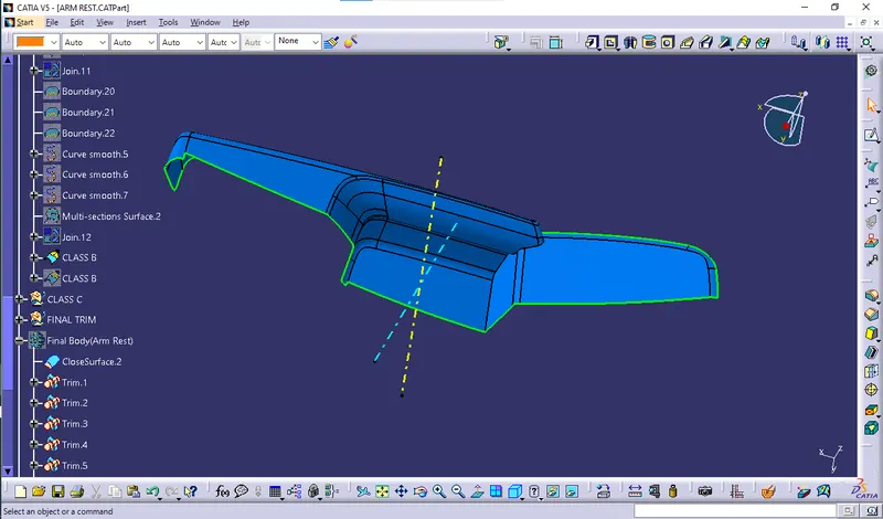 To achive Class B offset i refered master section for thickness input.
4. Class C Creation:
To create the class C, I extract the class A boundary curve in 3 to 4 batches then I did sweep with input of tooling axis draft direction and extracted the sweep end portions then to connect the extracted surface I did used trim comment.
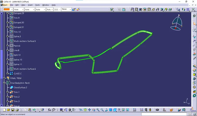
Class C+ A:
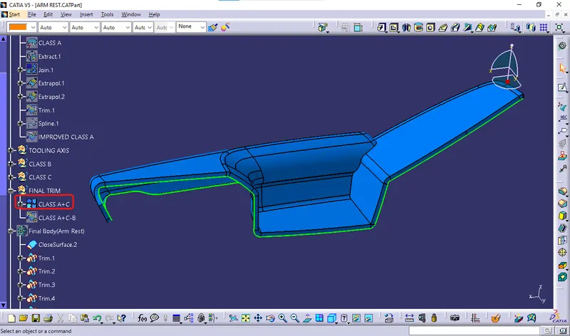
These Created Class C join with class A and then I checked the boundary line and its got error in one portion so I extracted the class C as well aside of class a then trim with class A.
And then I got result is Class C + A.
5.Final closed surface creation (Final Trim):
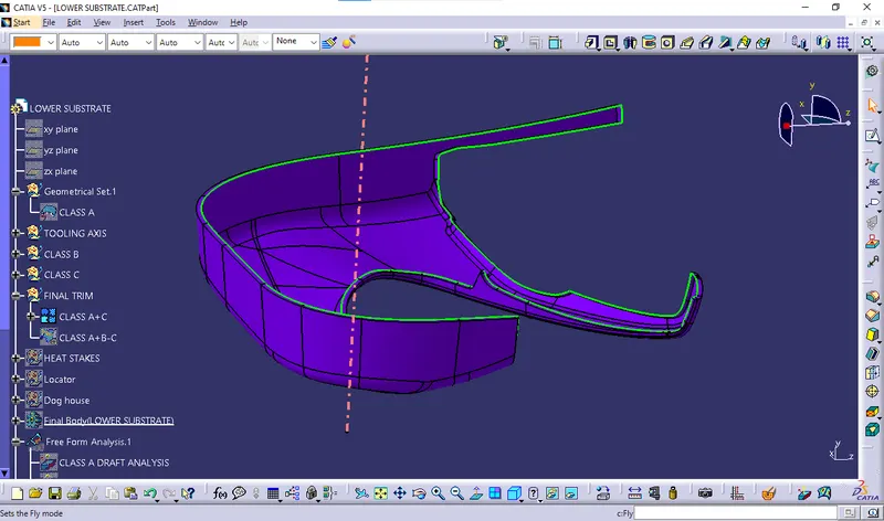
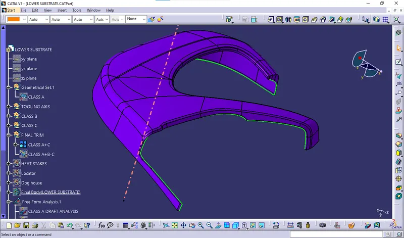
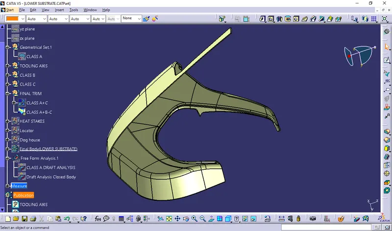
I trimmed the class C+A with Class B to create final closed surface in order make them solid.
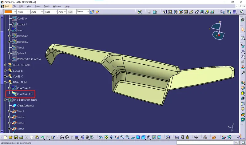 I had evaluate my closed surface of arm rest and it got cleared the test there is no any boundary found and it ready to make part body with thicken the closed surface. 6. Closed surface thicken by solid.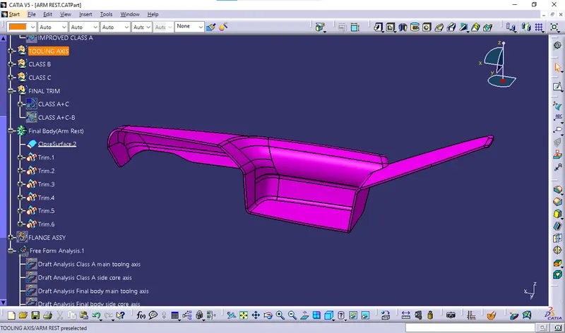
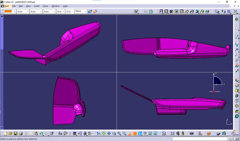
7.Draft analysis for solid part
With help of part design I thicken the closed surface and I just tried for draft analysis and its cleared the draft analysis. Draft anaysis with Main Tooling Axis:
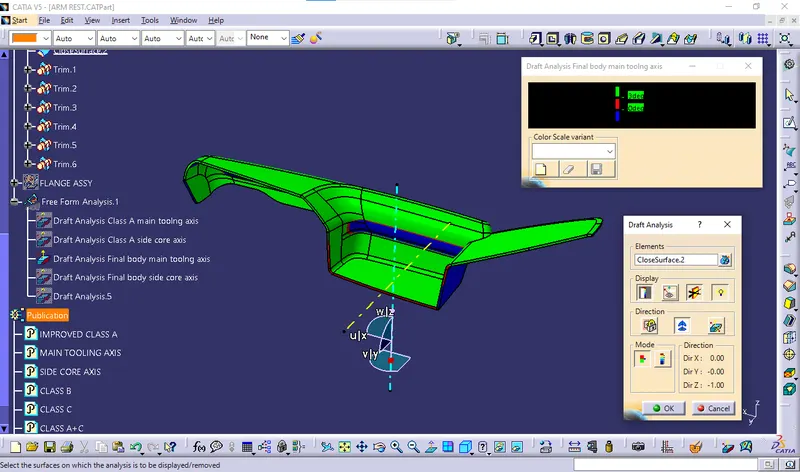 Draft anaysis with SideCore Axis: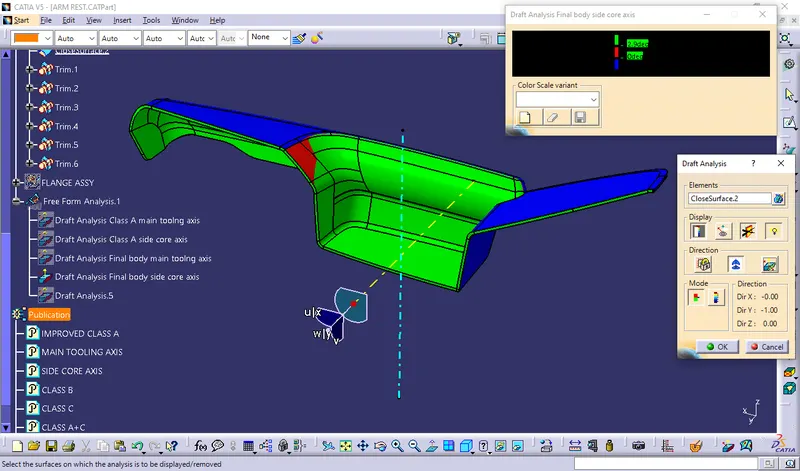
8.Parting line creation & tooling feasbility check
So before going to make engineering features we have to checkout tooling feasibility here tooling is the sense we demonstrate the core & Cavity manufacturing feasibility for that we have to create parting surface.
Parting surface is the surface between our components class C side surface which can help to decisions whether the created component can easy eject able from the and we can check it to make tooling axis normal to view mode and see their class C surface looks angular or not.
If the class C is in angular then our component ready to move for next process.
Parting line creation & tooling feasbility check
Parting line creation:
Parting line is the intersection line between the class C+A & Class B.
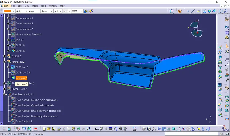
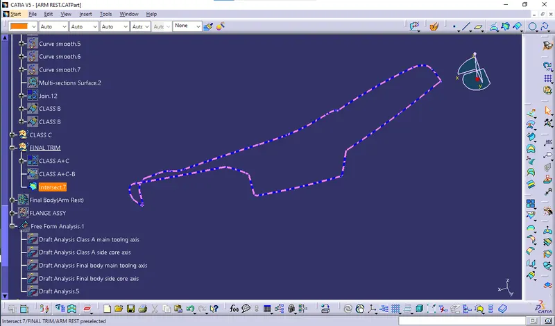
9. Engineering feature creation:
Now engineering features need to make for assemble the component with door trim panel sub assy.
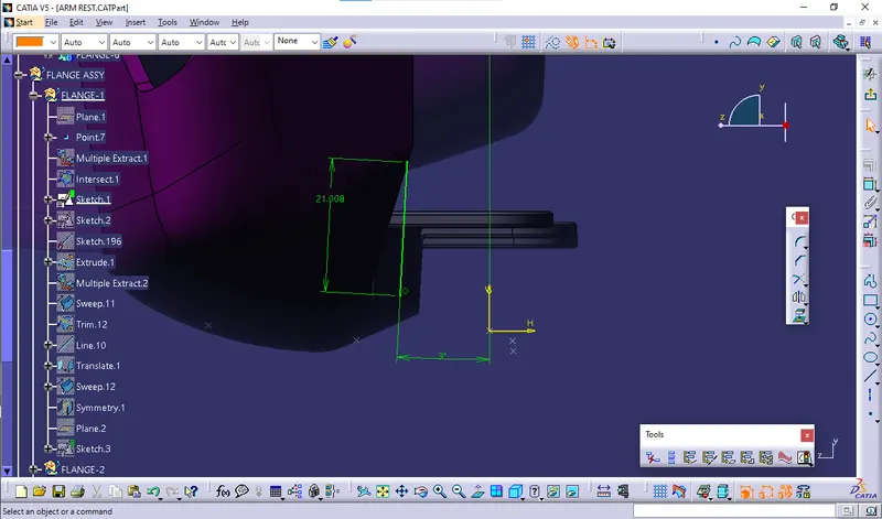
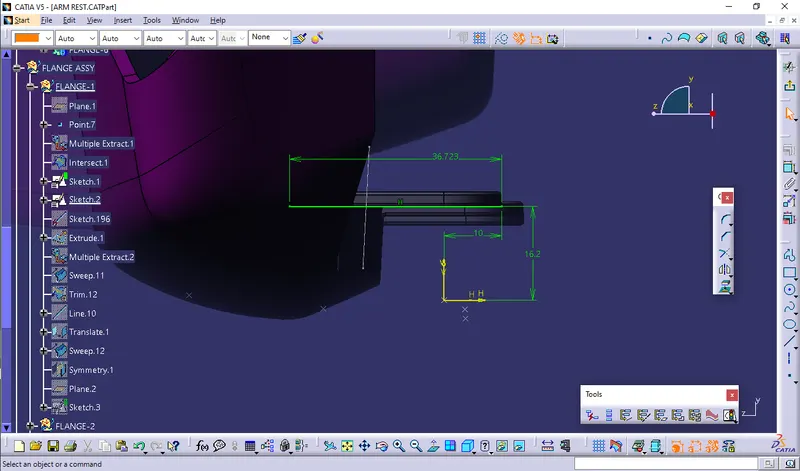
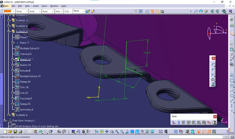
According to provided master section inputs flange shape dimensions.
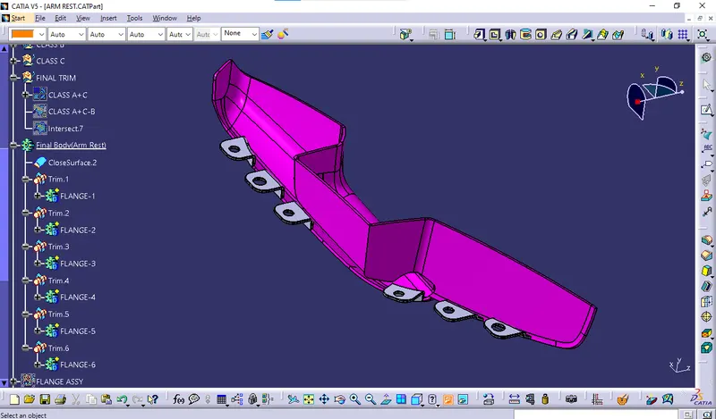
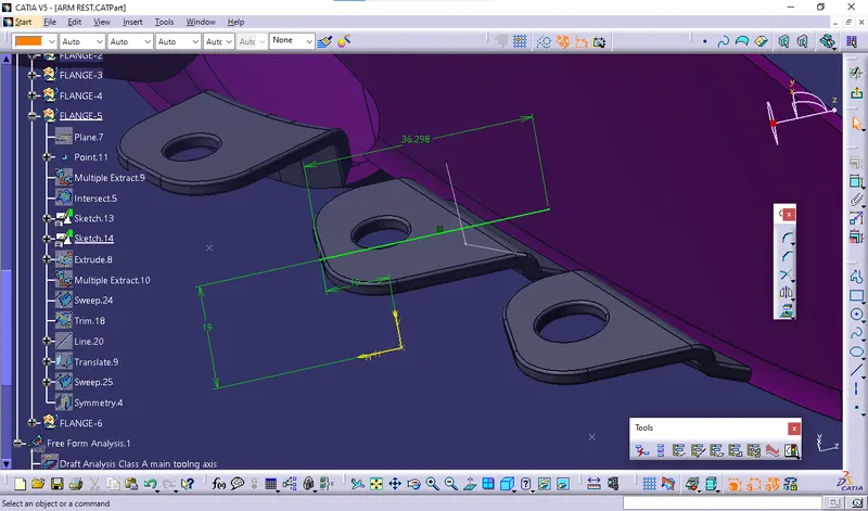
With input of this master section we decide to make flange on arm rest at various locations according the general assembly principle of 3-2-1 assembly.
We should arrest the component on 12 face of direction moving possibility with providing 3 axis locking process. FINAL BODY VIEWS WITH FLANGES: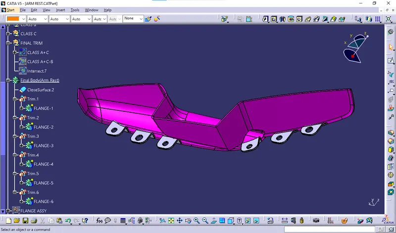
 Draft Analysis for Final body with flanges: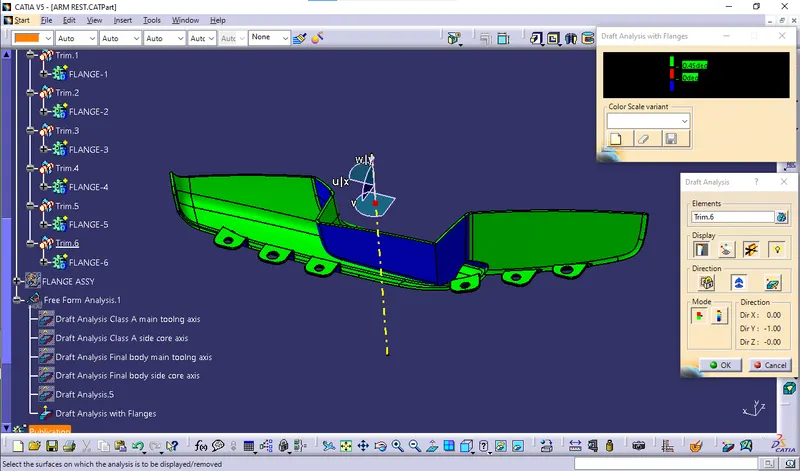

10.Material addition:
I provide plastic material as per normal material providing features.
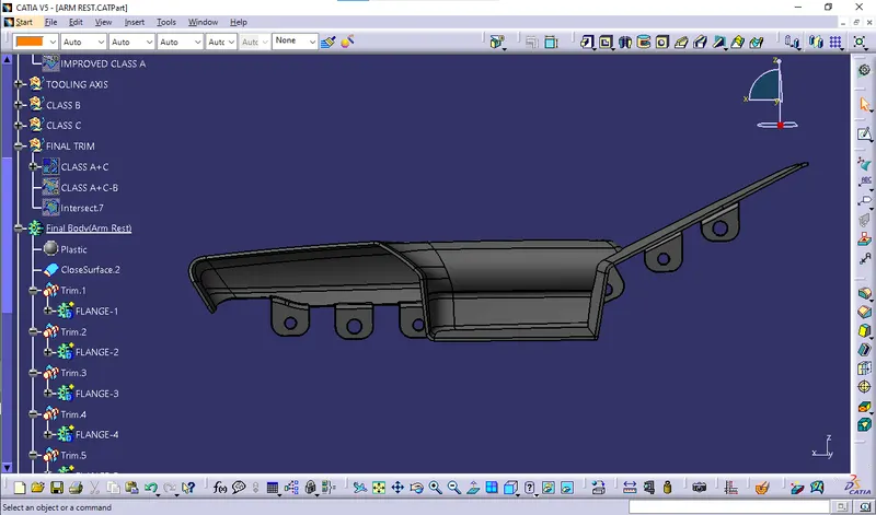
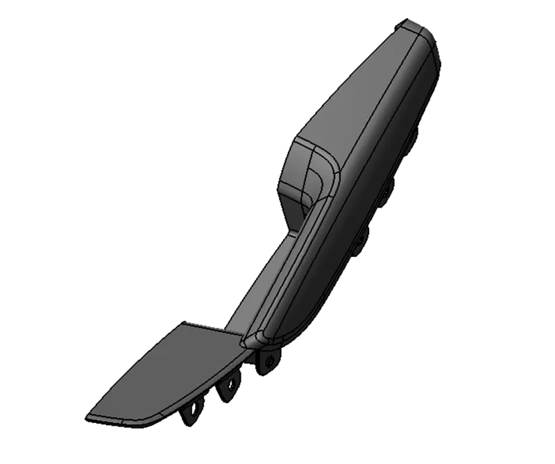 The above view is complete solid rendering view of arm rest along with engineering features.
LOWER SUBSTRATE
The below image is provided class A.
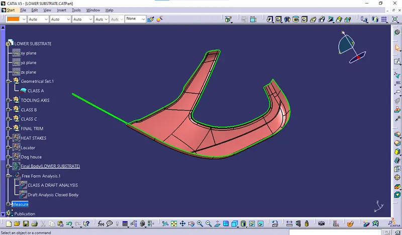
From the input of our improved Class A surface, i had started to work in order to focus of closed solid body creation.
To create solid body of arm rest we have to do following process,
- Tooling axis creation
- Draft analysis
- Class B creation
- Class C Creation
- Final closed Surface creation.
- Closed surface thicken by solid.
- Draft analysis for solid part
- Parting line creation & tooling feasbility check
- Engineering feature creation.
- Material addition.
The above procedure same for all following door trim panel and few changes will be there as per class A inputs and master section inputs. 1.Tooling axis creation:
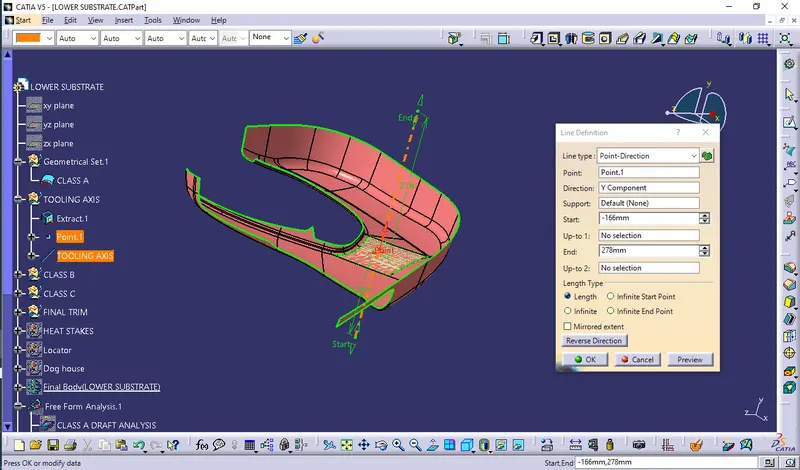
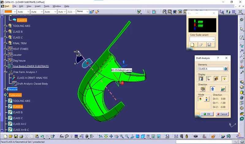
2. Draft analysis:
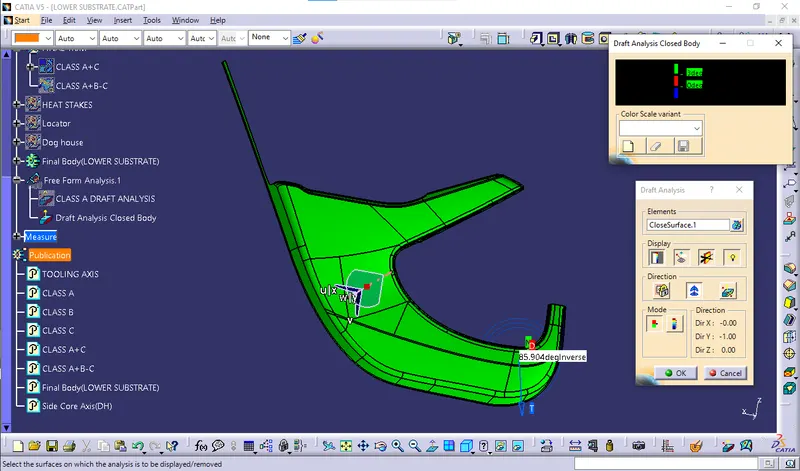
Provided class A got cleared results as per draft analysis so we can take this to proceed for further process.
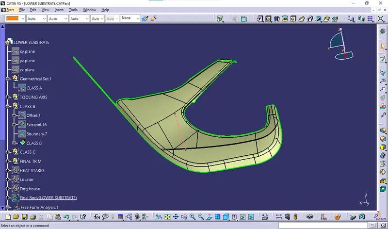
 3. Class B creation:
  4. Class C Creation: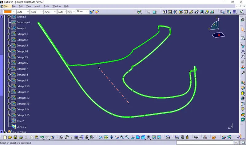
5.Final closed surface creation:
Class C+A,
 Final Trim,
  6. Closed surface thicken by solid: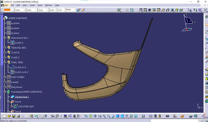
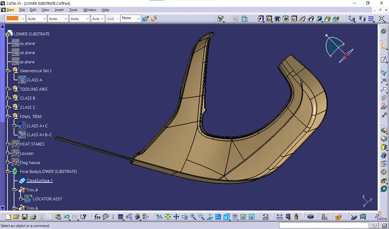 7. Draft analysis for solid part:
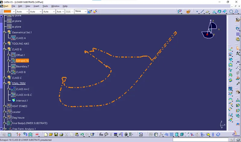
  8.Parting line creation & tooling feasbility check: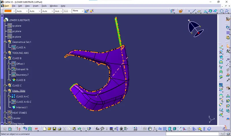
 9.Engineering feature creation: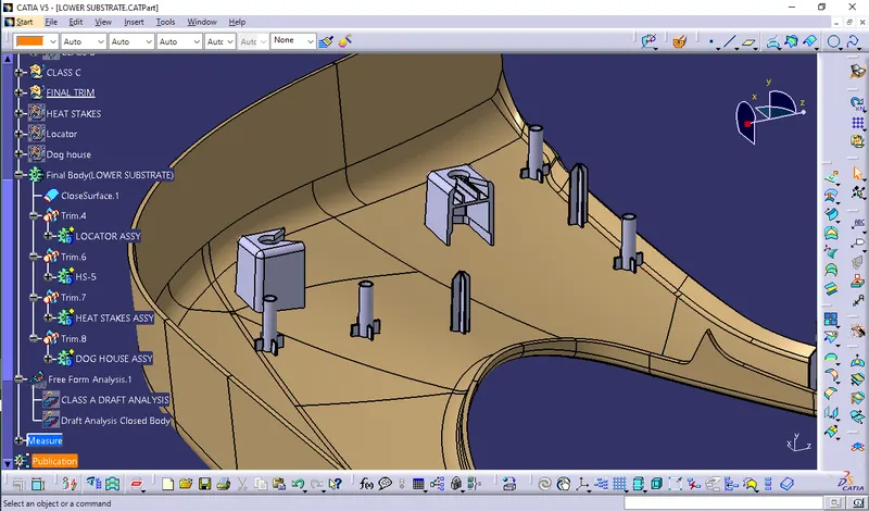
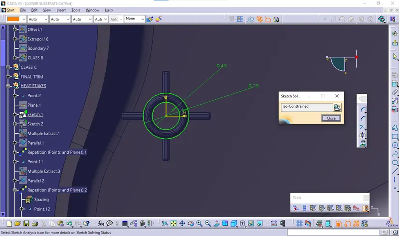
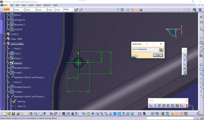
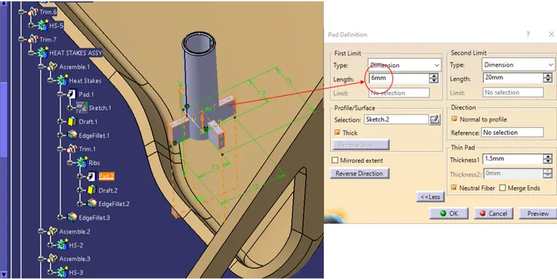
Heat Stake Sketch :
Take 5 & 7.5mm Dia Circles As Shown in figure below.
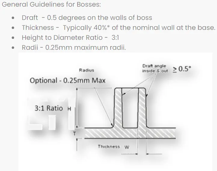
Here heat stakes created with draft 0.5 degree, fillet radius is 0.3mm and wall thickness is 2.5mm.
heat stakes designed by following the design rules.
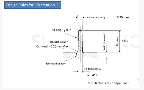
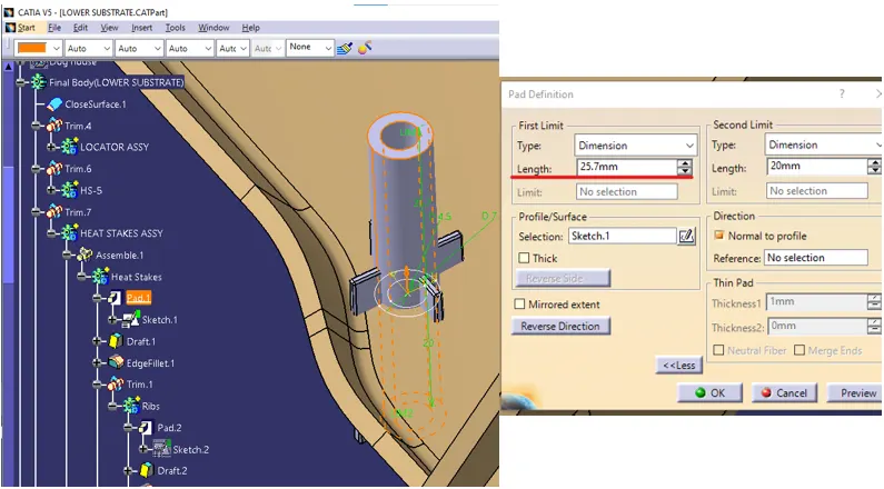
Next, the profile is extruded, to find the height,h=Wall thickness * 5
=2.5*5
= 12.5 mm
Therefore, the height is 12.5 mm. BUT IN MASTERSECTION it is 25.7mm so we consider 25.7mm height.
The extruded surface is thickened,
Thickness,w=0.4*t
=0.4 2.5
=1mm
Therefore, the thickness of the rib is 1 mm. we have given nominal thickness 1.5mm with neutral fiber.
LOCATORS
Typically, locating pins are used for controlled, fine tolerance positioning of a work piece.
A 2-way locating pin restricts motion along 1 axis (or 2 degrees of Freedom), like a round pin in a slot. Likewise, a 4-way pin restricts 4 degrees of freedom along 2 axes. A round locating pin located concentrically in a hole is a common application of a 4-way pin, and helps to further secure the piece.
Here 4-way locator created with thickness 1mm ,draft 0.5 degree and the fillet value is 0.3 mm .
4 way Locator Sketch :
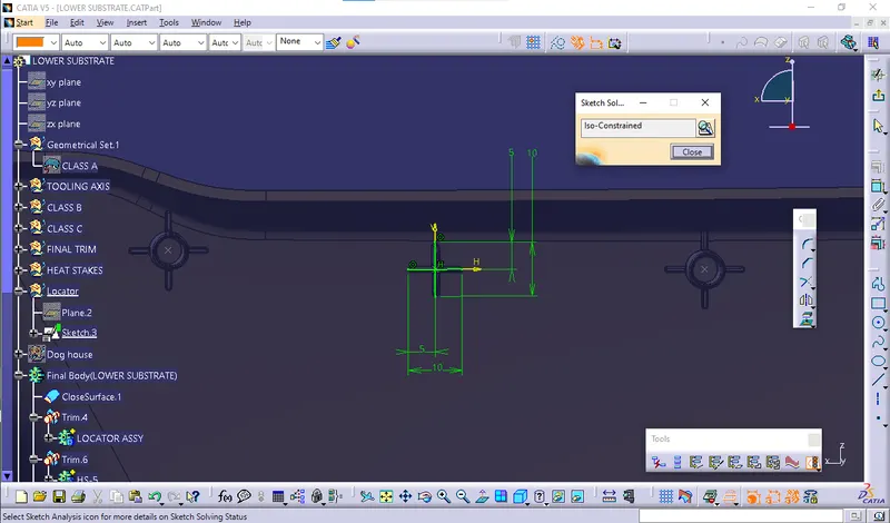 Note:Loctor height is given 30mm which is more than heat stakes since,location of two parts happens first later Fixation takes place.
DOG HOUSE DESIGN:
- Dog house is an engineering feature used in the plastic trim design.
- Dog houses are used as supporting features. Sometimes other engineering features like snaps; locators, etc. are mounded on them to increase their strength.
- These pins are used for the assembly purpose .
- These pins are guided into the sheet metal body.
- The pin is assembled over the dog house on one side and other into sheet metal.
- These pins are used for the assembly purpose .
- These pins are guided into the sheet metal body.
- The pin is assembled over the dog house on one side and other into sheet metal.
- These pins are used for the assembly purpose .
- These pins are guided into the sheet metal body.
- The pin is assembled over the dog house on one side and other into sheet metal.
- Dog houses are designed to avoid SINK MARK created on the CLASS-B surface by screw bosses and to solve the length issues when giving screw bosses which need to be assembled to other components.
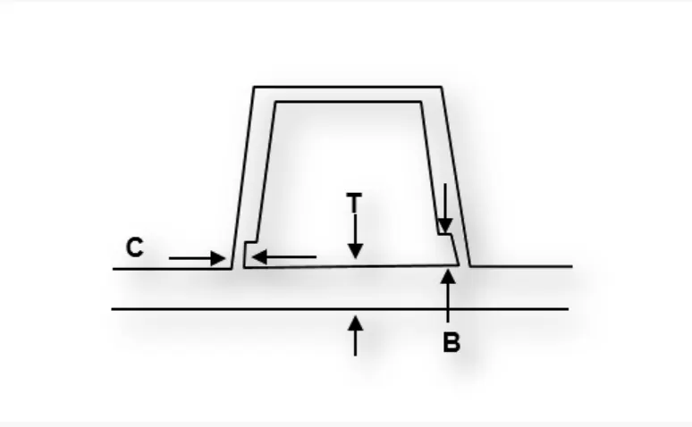
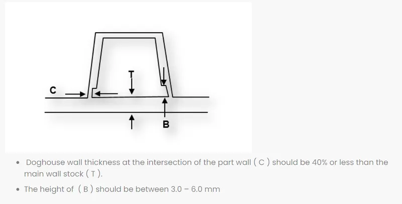
C" is where the doghouse contacts the backside of the surface.
Doghouse wall thickness at the intersection of the part wall ( C ) should be 40% or less than the main wall stock ( T ).
The height of ( B ) should be between 3.0 – 6.0 mm.
DOG HOUSE SKETCHES: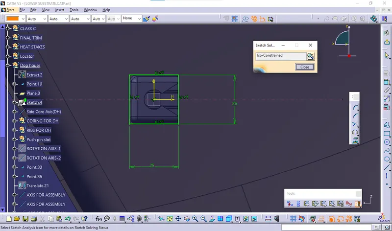
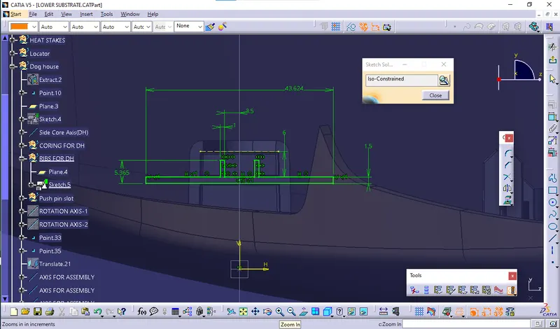
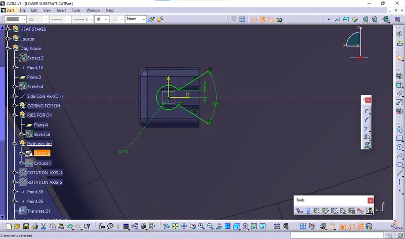 Coring for Dog House:
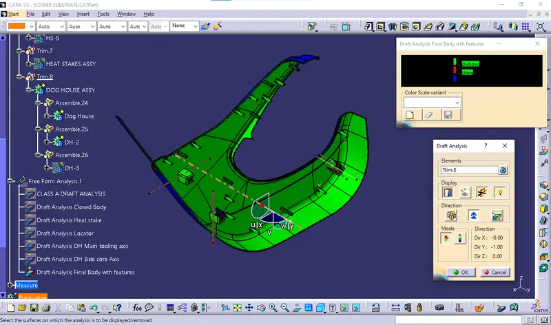
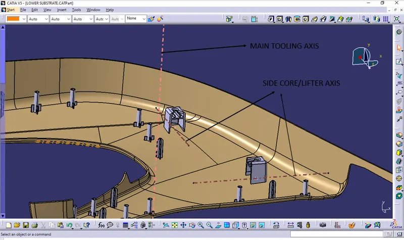
 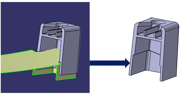 Lifters help to release internal undercuts or internal faces with no draft. After the part has cooled, the lifter pushes up at an angle, which removes the undercut section from the mold, and retracts from the undercut during ejection DRAFT ANALSIS: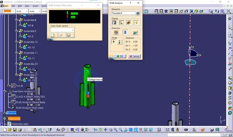
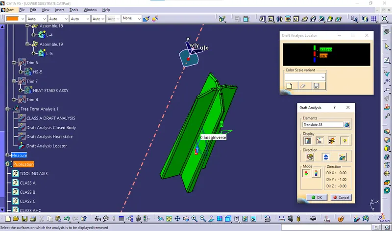
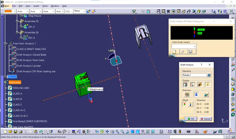
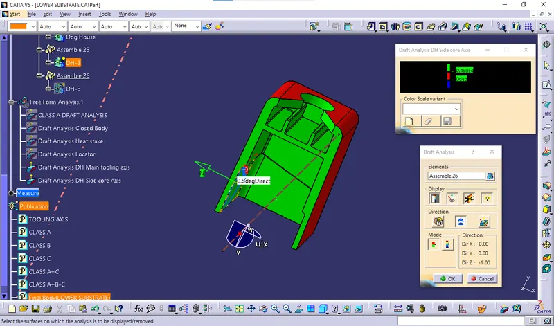 FINAL BODY VIEWS: ISOMETRIC VIEW
 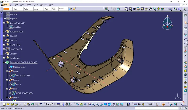 FINAL BODY DRAFT VIEWS: ISOMETIC DRAFT VIEW
  FRONT DRAFT VIEW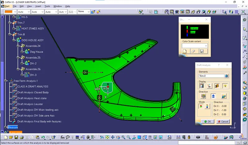
10.Material addition:
The view shows with material addition of plastic.
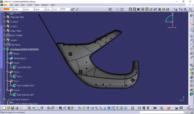
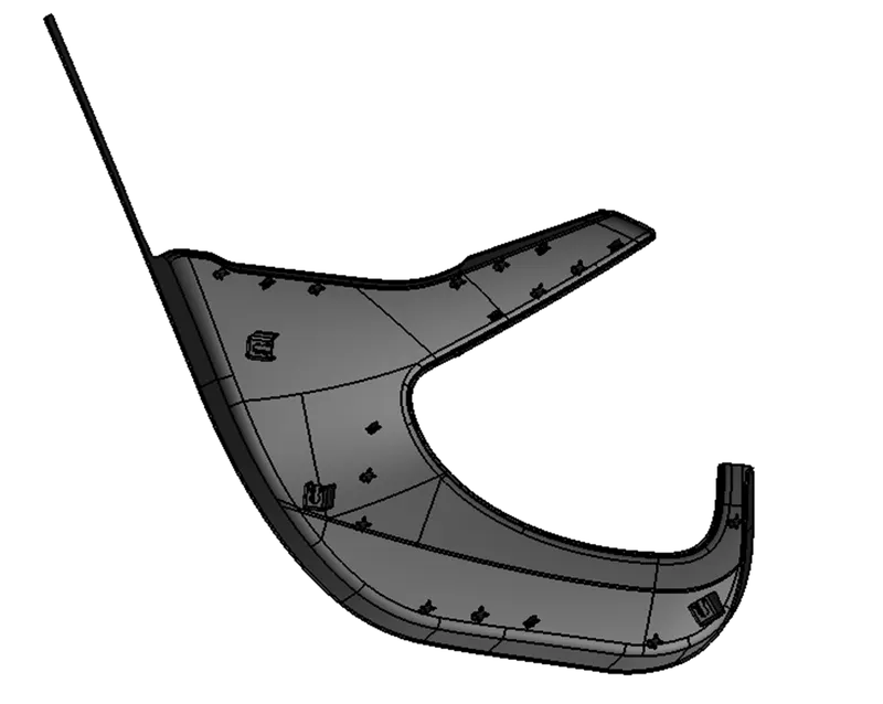 The above view is complete solid rendering view of arm rest along with engineering features.
MAP POCKET
The below image is provided Class A surface,
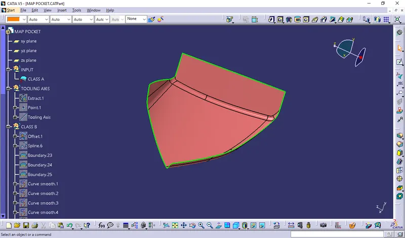 1.Tooling axis creation:
 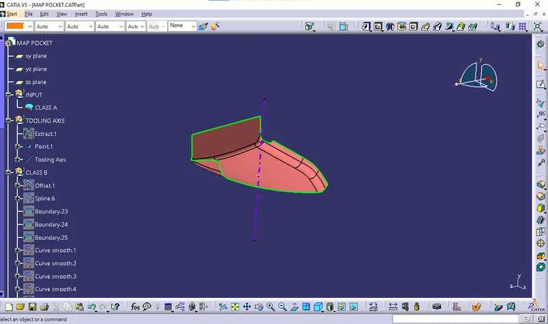 I have used point & Direction method to create Tooling Axis. 2. Draft analysis:
 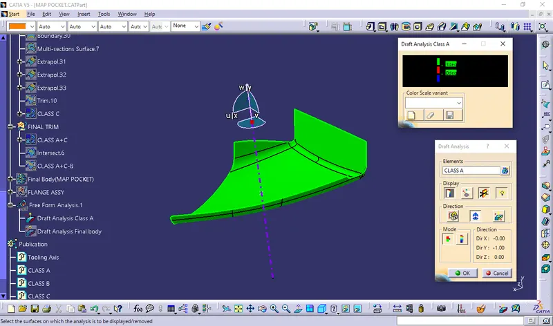 Provided class A got cleared results as per draft analysis so we can take this to proceed for further process. 3. Class B creation:
 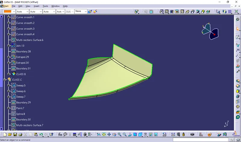 4. Class C Creation: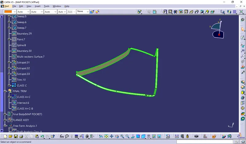
5.Final closed surface creation:
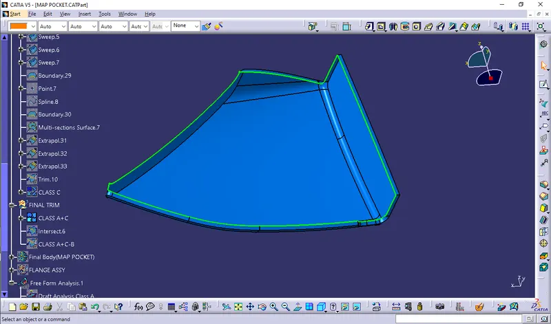
Class C+A,
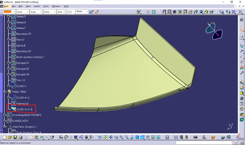
 Final Trim,
  6. Closed surface thicken by solid: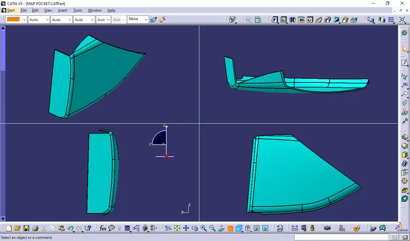
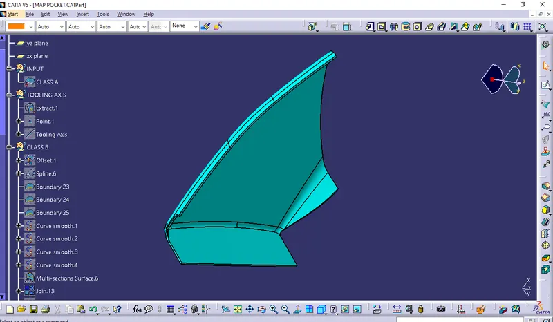 7. Draft analysis for solid part:
 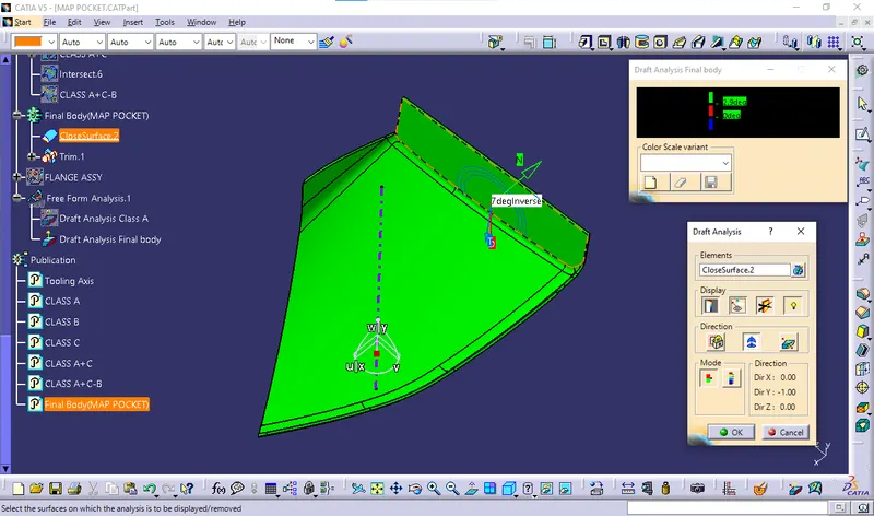 8.Parting line creation & tooling feasbility check:
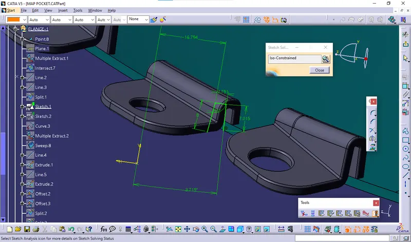
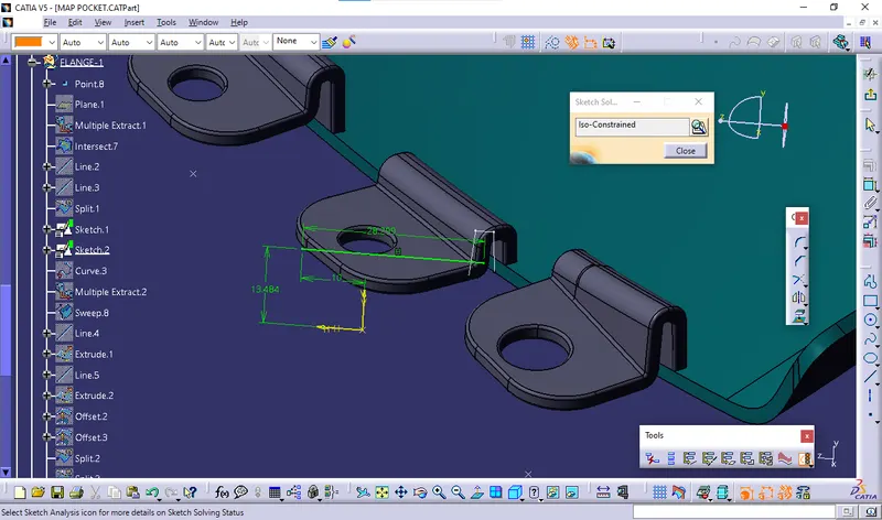
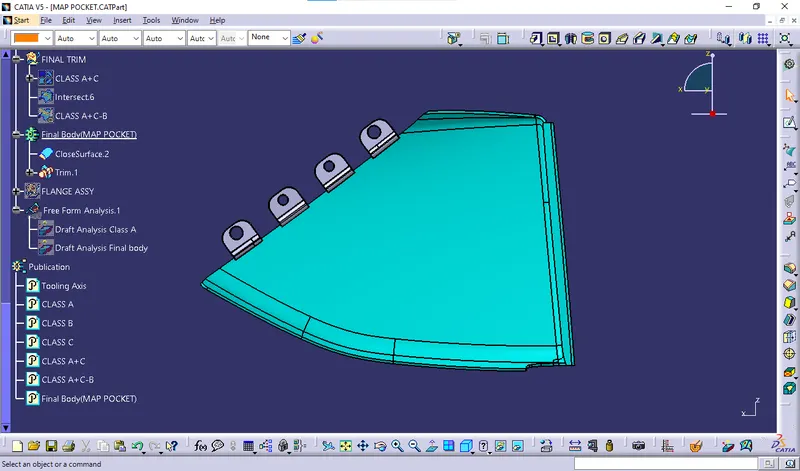
 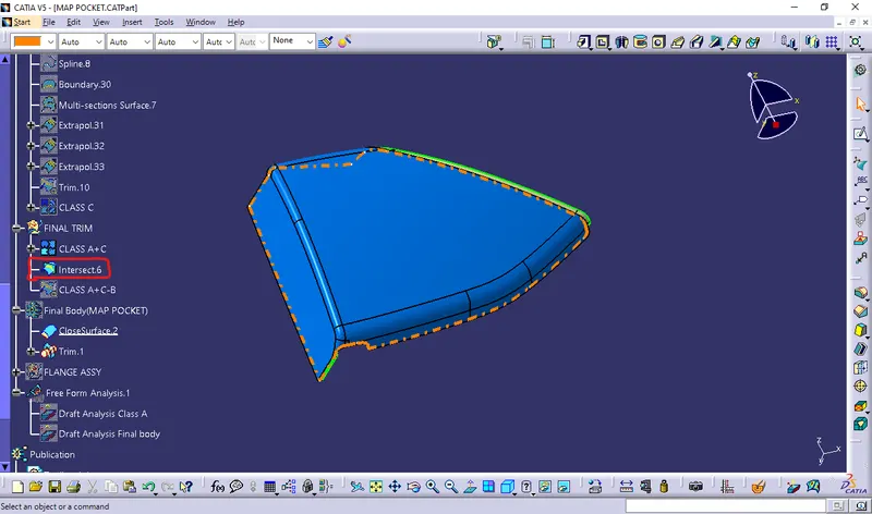 9.Engineering feature creation: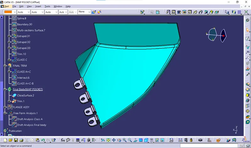
 Draft Analysis for Final body with flanges: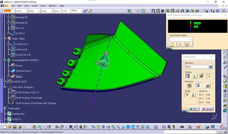
10.Material addition:
The view shows with material addition of plastic.
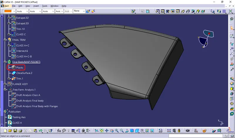
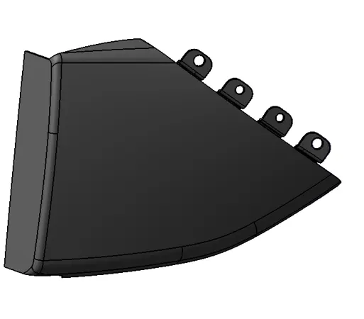 The above view is complete solid rendering view of arm rest along with engineering features.
BOTTLE HOLDER
The below image is provided Class A surface,
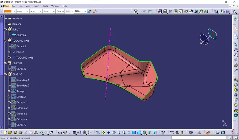
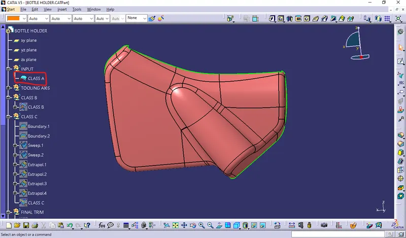 1.Tooling axis creation: Here, I used point & Direction method to create Tooling Axis.
  2. Draft analysis: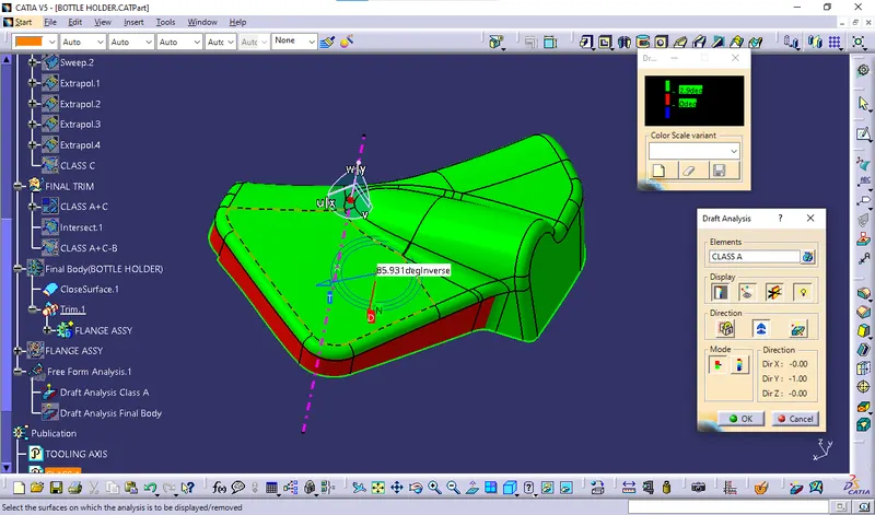
Provided class A is not cleared the draft analysis method because we got found 0 Dgree angle in some portion of class A which create issue to make tool core & Cavity.
Below black color elipse shape highlighted portions are got found the 0 Dgree refer below shown in the images,
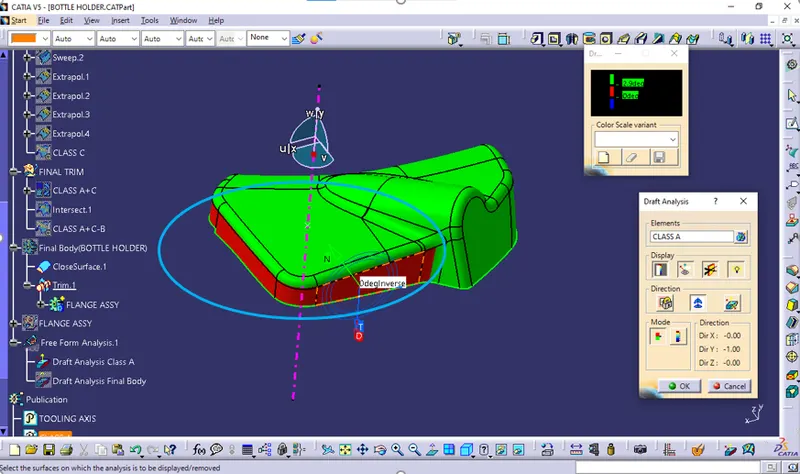
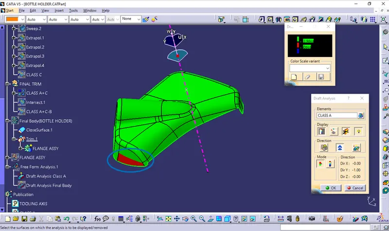
I have informed to class A given sources but in industries we have to inform the issue to class A Designer or concerned person in charge is very necessary.
And as a plastic designer we dont have authorised modify the class A. But here in order to completeion of task we have to took it further process.
3. Class B creation: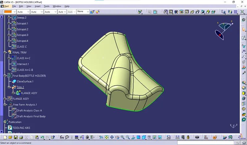 4. Class C Creation:
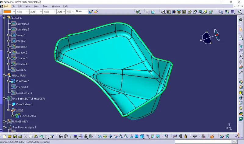
 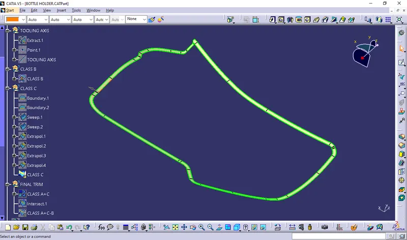 5.Final closed surface creation: Class C+A,
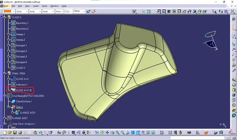
  Final Trim,
  6. Closed surface thicken by solid:
 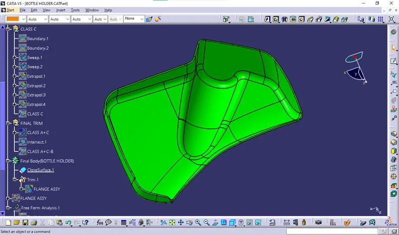 7. Draft analysis for solid part:
 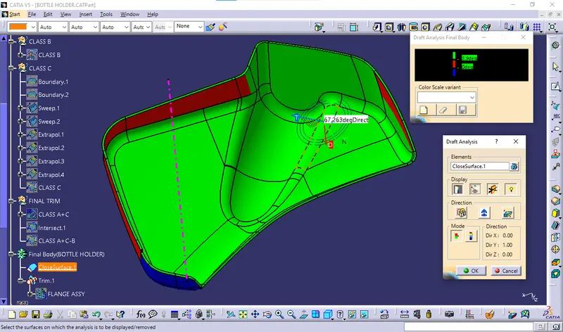 In the closed solid body draft analysis report shown the class A issue carry forwarding to the same of further process. 8.Engineering feature creation:
 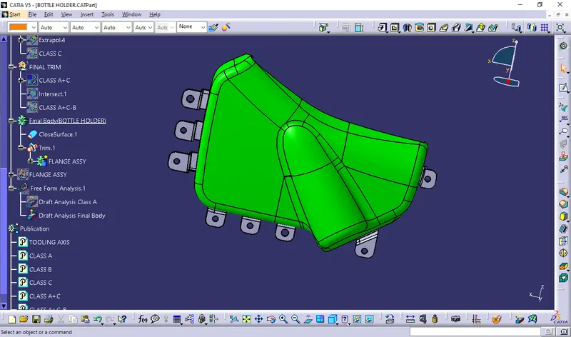 Draft Analysis for Final body with flanges: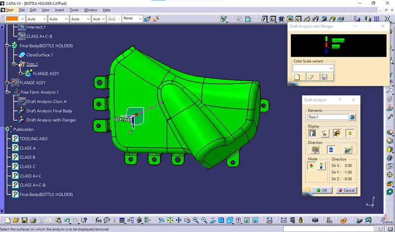
9.Material addition:
The view shows with material addition of plastic.
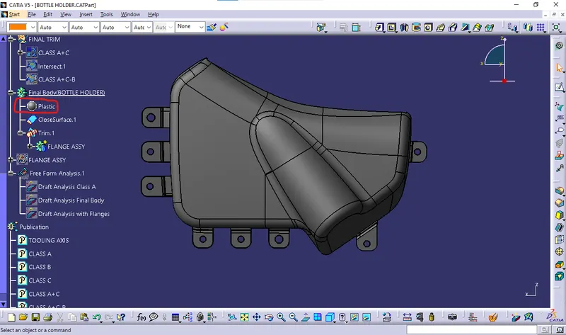
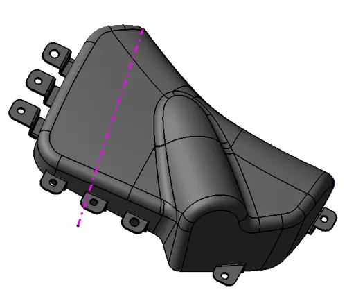 The above view is complete solid rendering view of Bottle Holder along with engineering features.
PUSH PINS:
- These pins are used for the assembly purpose .
- These pins are guided into the sheet metal body.
- The pin is assembled over the dog house on one side and other into sheet metal.
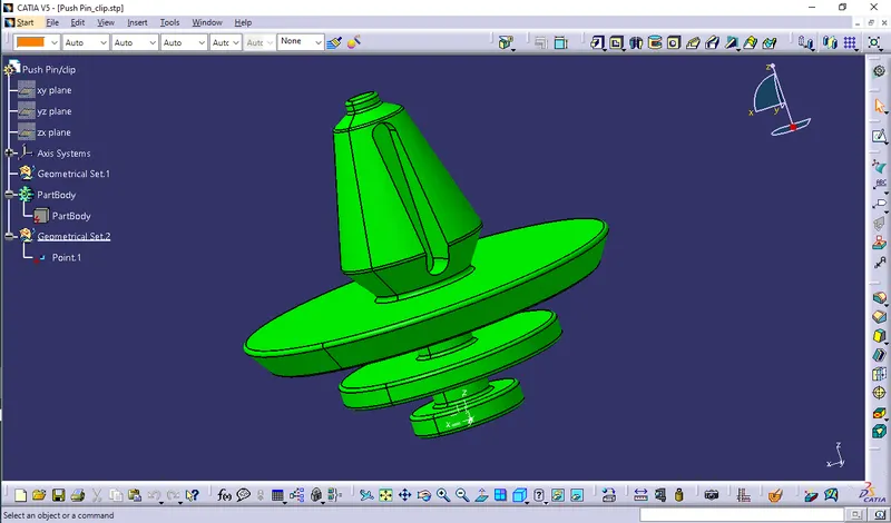
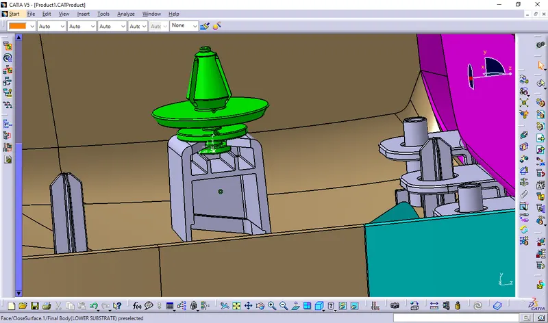 Push pins are assembled by using Coincide Constraint
FLANGE:
The purpose of the flange was to provide slots for the heat stakes and locator which are required to assemble the two components together and constraint the motion between them. It is basically a counter part.
- These flanges will be build on the components for the fittment purpose with lower substrate.
- The hole at center will be guided along the heat stakes.
- Later top portion of the heat stake will be melted over it.
- The flange should rest on the supporting ribs on side. Note:Flanges are created along C-Surface so that we can use same tooling and reduce defects. If we create flanges from B-Surface leads to sink mark and we need to provide seperate side core leads to increase in manufacturing cost.
FINAL ASSEMBLY:
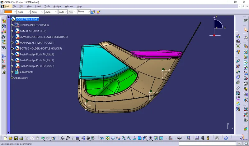
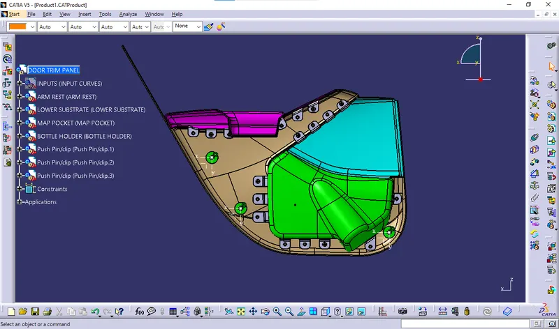
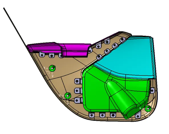
The components that are created in separate part files and then inserted into assembly files they are assembled at their working position by applying constraints to them. To create an assembly using this approach, it is recommended to insert the first components and fix their position after properly orienting them in the 3D space the components can be inserted and positioned with reference to the first components.
DIFFERENT VIEWS OF FINAL ASSEMBLY: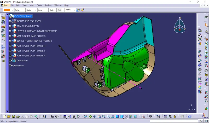
 Material Mode View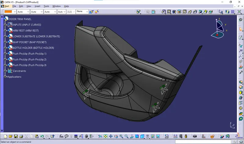
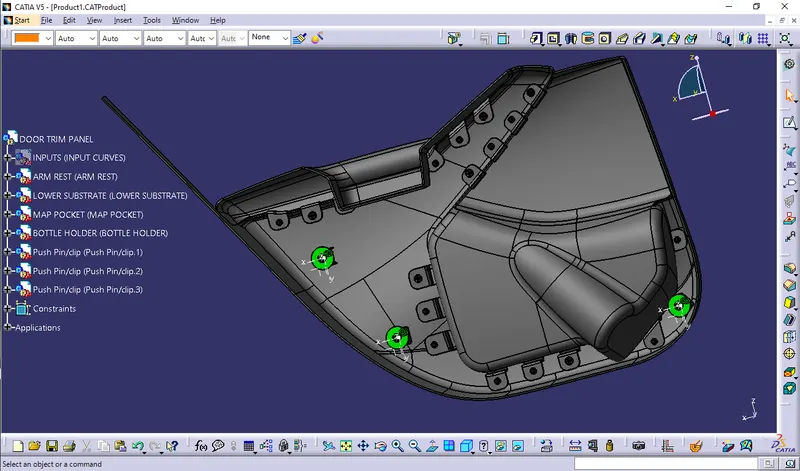 Door panel side(Class B side view)
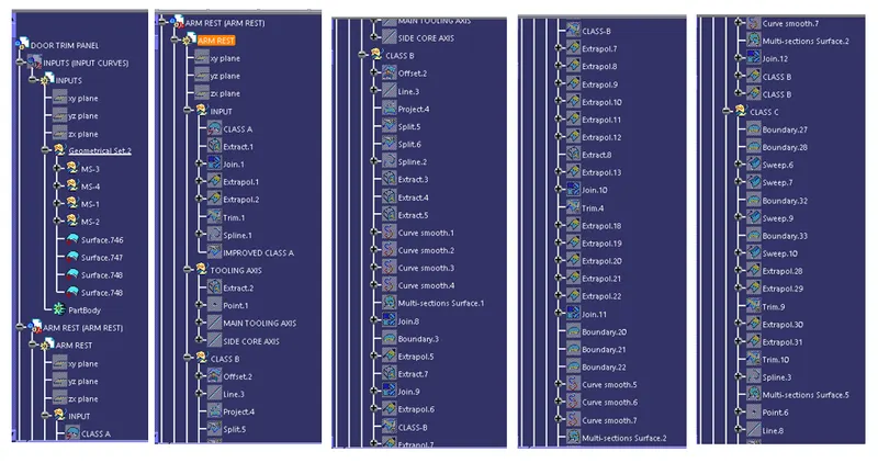
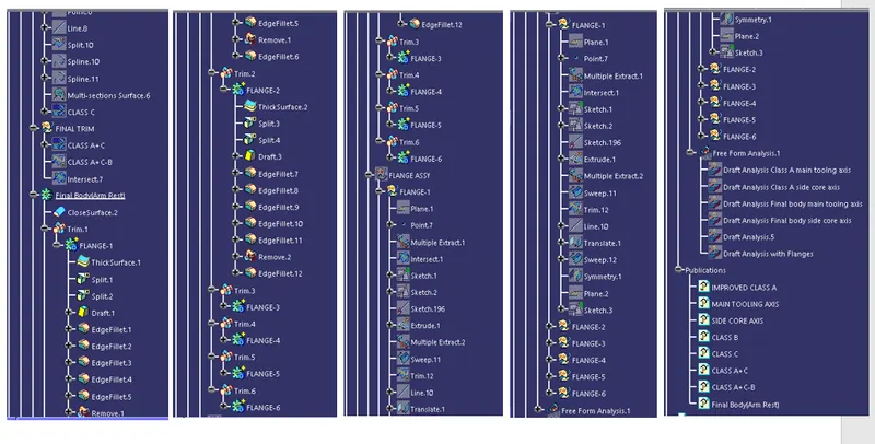
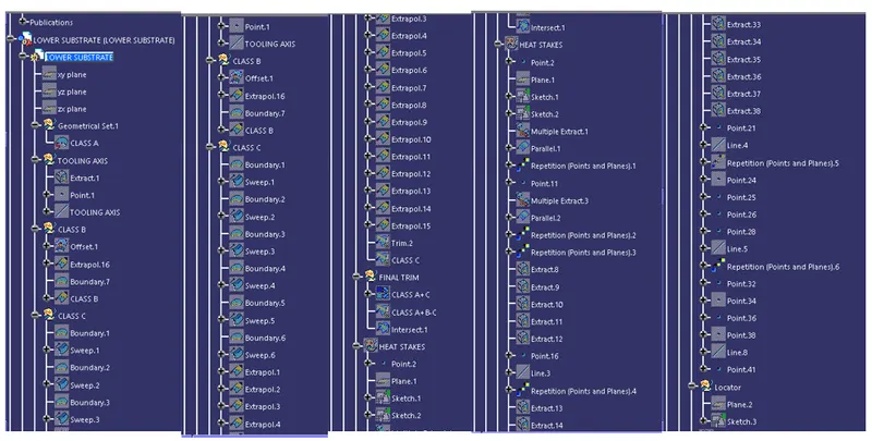
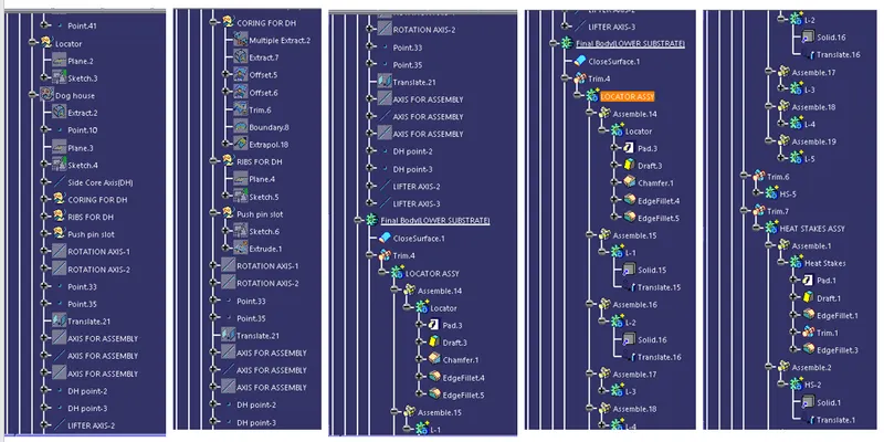
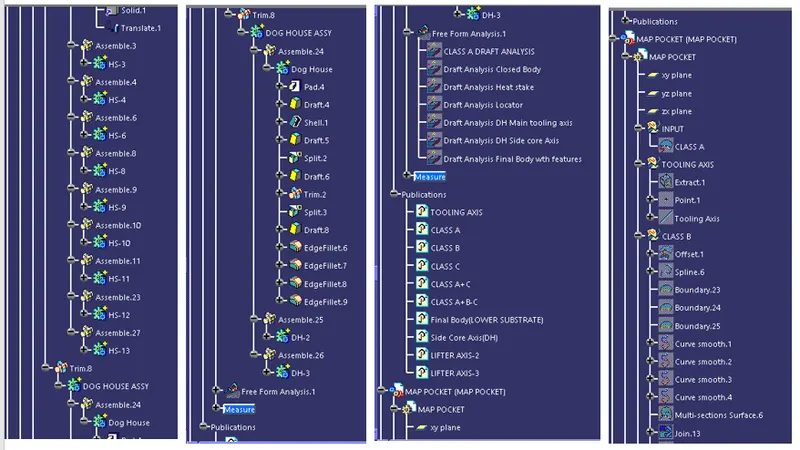
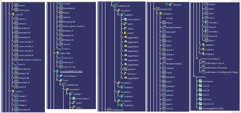
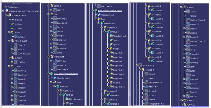
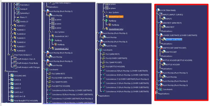
 TREE STRUCTURE: