Week 12- Final project
AIM :-
Development of a Door Trim panel & create a B_side features as Push pin with Dog house for Lower substrate – Door panel attachment Use heat stakes for part to part attachment.
ABSTRACT :-
- To Creation of CAD model considering following inputs as like in OEM and tier1 companies
- a) Class A surface
- b) Nominal thickness : Refer master sections
- c) Attachment strategy :
- Find a attachment strategy for the door panel complete work.
Output required:
- Create thickened part using master section for reference
- Create the mounting features as per design guidelines in the industry and with master sections
- Apply material details :
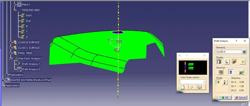
- Draft analysis & Tooling analysis
- Creation of parting lines and check tooling feasibility
SOLUTION & PROCEDURE FOLLOWED :-
Firstly we have to provided the master section developement with arm rest , lower substrate, bottle holder & map pocket in a single step file. Another step file of a push pin/clip. So we need to first convert into Cat_part File as well.
Master Section :-
- Master Sections are the guides for design requirements which shapes the component after technical styling of Class A Surfaces.
- Master sections are the guides for design requirements that decide the component packaging after technical (Styling, Concept, or Class-A) surfaces. Creating this master section should need 5 to 6 years of experience.
- This helps you to decide the feasibility, clearance, packaging, and fixation strategy before working it on a 3D. We have a master section.
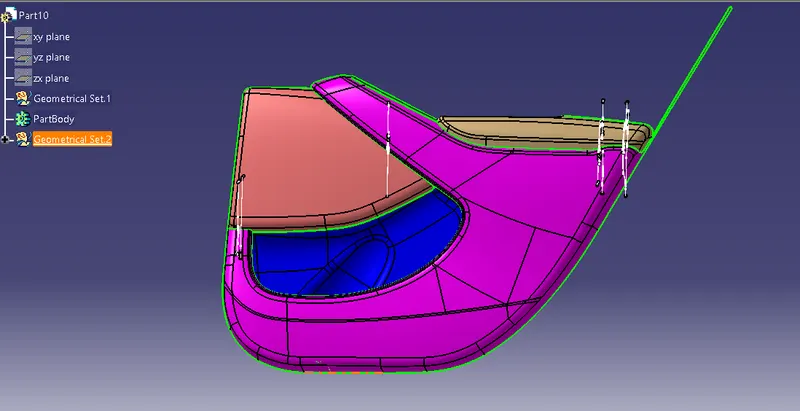
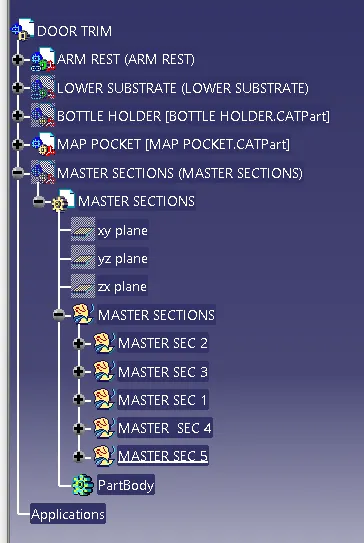
Then Create a new Product file & add seperate part within it with master section also seperate part as well. Then work on on seperate-seperate part.
PROCEDURE_1 :- Creation of closed Soolid surface / Body with provided Class A surfaces .
We have provided 4 types of seperate Class A of a different parts for the asseymbly. Namely as :
- Arm Rest
- Lower Substrate
- Bottle holder
- Map pocket
So we need to move step by step for the making of a closed body one by one as well.
1] Arm Rest :- move on making a closed body.
From the single product file we have add the sub_parts in it. First we hide other part & work on a Arm Rest Class A surface to making a Closed Body Surfaces .
A] Class A surface ckecking :-
The bigun procedure of any component making we need to check the first the Class a checking with whole boudary visualization & find out any patches is there or not. If there is any issue about the class A surface we need to inform the referance team Design engineer to solve the problem or it is neccesary to inform as well.
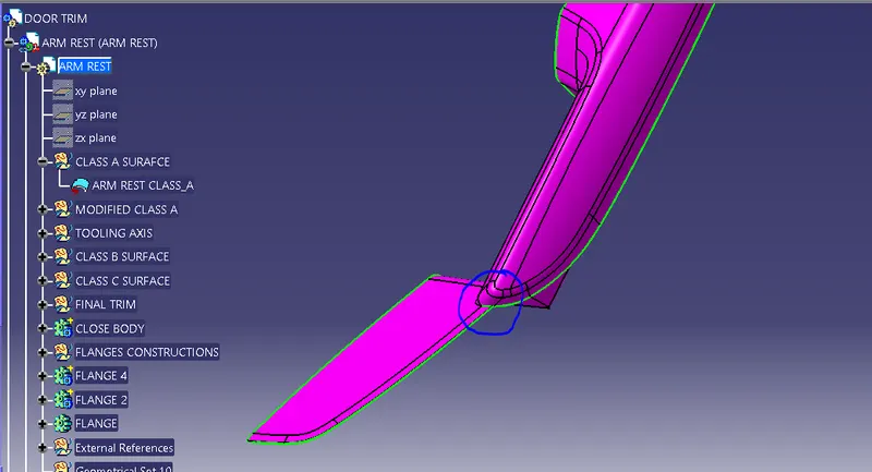
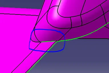
B] Modification of the class A :- The modification is necceasry of the class A surface for the better & avoid obstacles while creating the B & C surfaces. So we need to remove the patches from it. So there we need to get a join & remove sub-element there. After getting extract necessary surface, extrapolate to it , trim it & again join this timed wth parent join with an merging distance 0.003 mm.
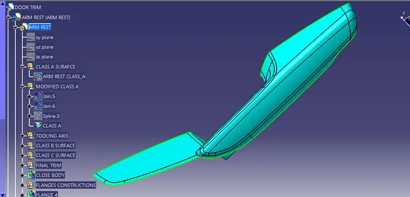
C] Tooling Axis Creation :-
Creation of Tooling Axis
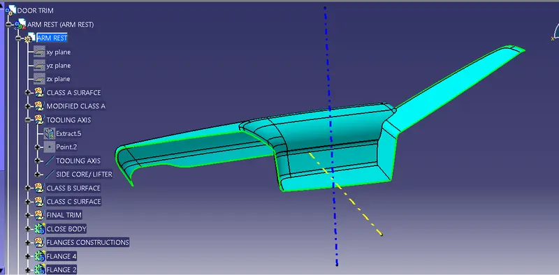
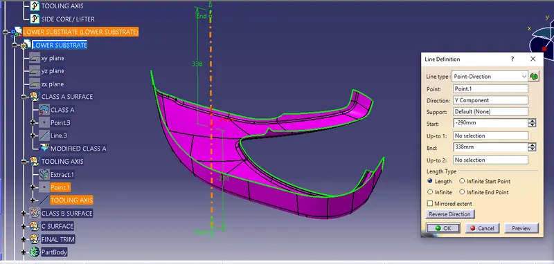
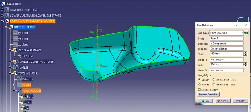
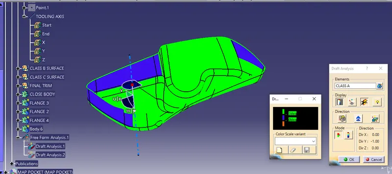
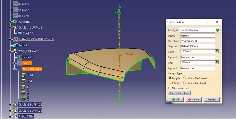
Tooling Axis :- In injection molding, the Class A surface is first analyzed to determine the axis or tooling direction that separates the molds. Tooling direction is critical for plastic product design because it determines mold direction. It is a main axis towards the direction the component ejject with also an core & cavity open or close.
So for the creation of tooling axis we need to understand & always keep in mind 3_ways basically.
- X,Y,Z direction method
- Normal to surface
- Bisecting method is is takes a referance from a master section.
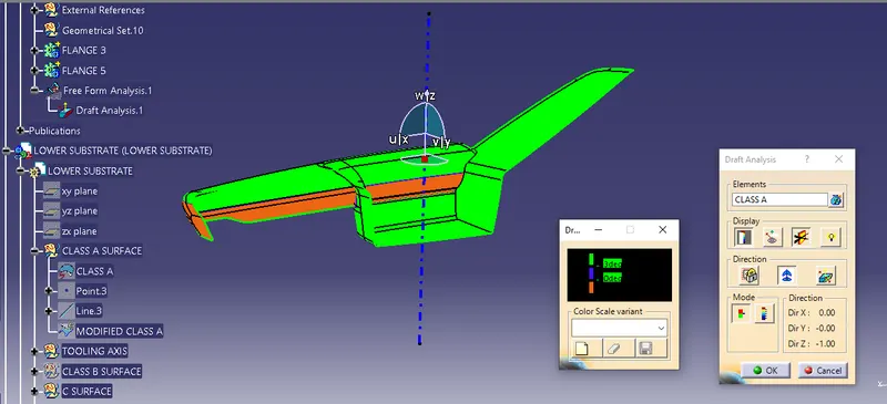
Here we have created the tooling axis by Y direction & side core Axis/ lifter as well.
D] Class B surface creation :-
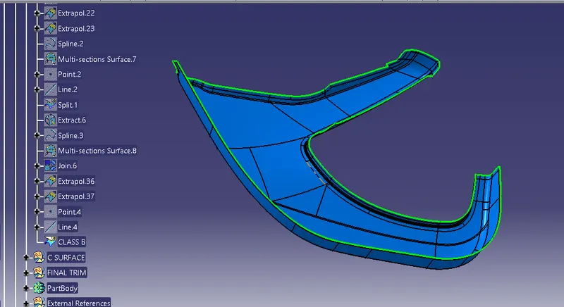
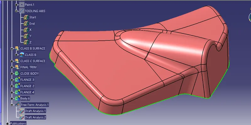
In this step we need to offset the class A surface with desired diamension so we take a 2.5 mm & it measured from the master section as well.
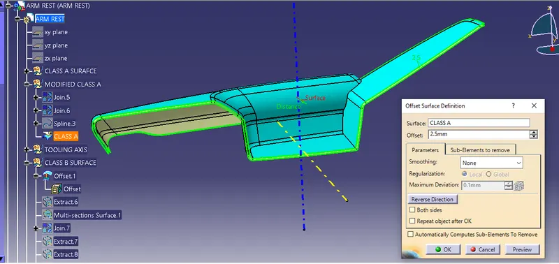
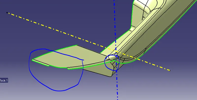
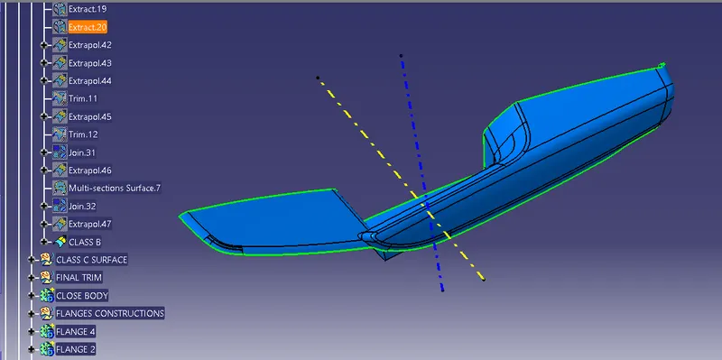
After offseted Class A we got a Class B surface, but we found a Sharp edges , patched area again & unfill surface so we need to moodification of it.
E] Class C surface Creation :-
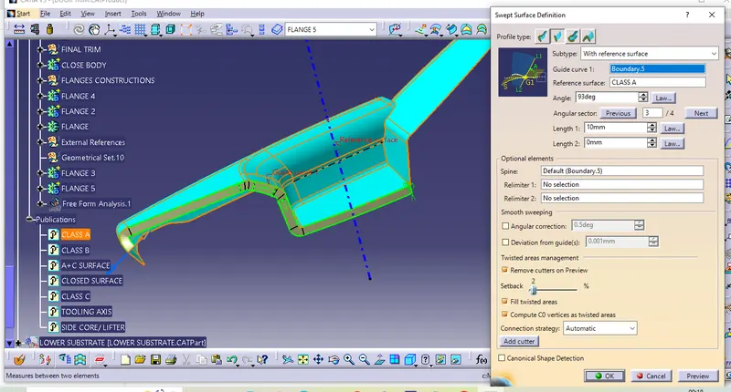
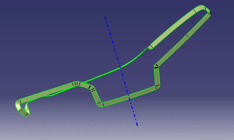
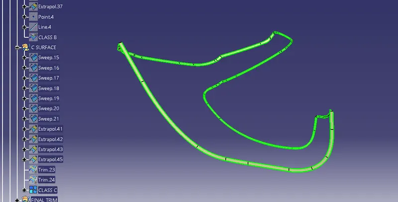
For creation & making the Class C surface we always need too take a Class A surface referance. And Apply a multiple sweeps near the bpundries.
- In this procedure we need the Class A again to as a referance for creation the Class_C surface.
- Here 2 types of Sweeps are used for the making class_C surfaces.
- The 2 types as 1st is taking a referance surface with an angle of 90 Degree &
- 2nd is with the draft direction with the angle of 3 Degree. In the referance with surfaces we take a referance as a Class_A & in the with the draft direction as a Tooling axis as well.
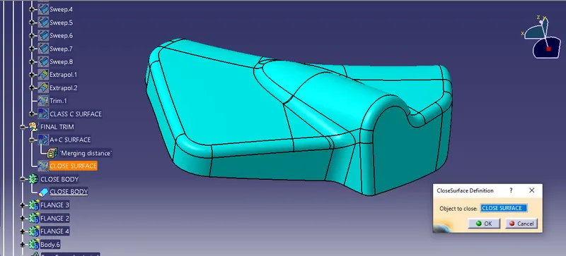
F] Final trim :- Final trim is a Cloed surface creation method .
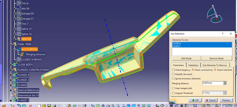
In this step we get a join bwtween the Class A & class C surface. & finally this join again trim with the Class B surface so we got a complete Close Body as well.
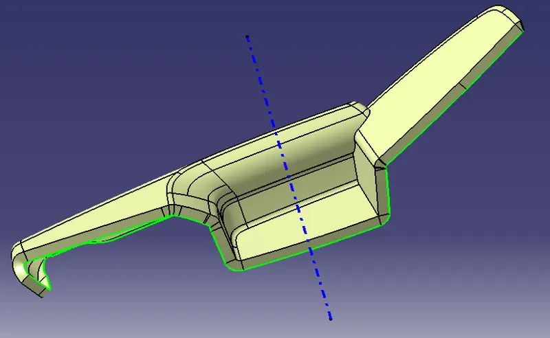
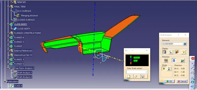
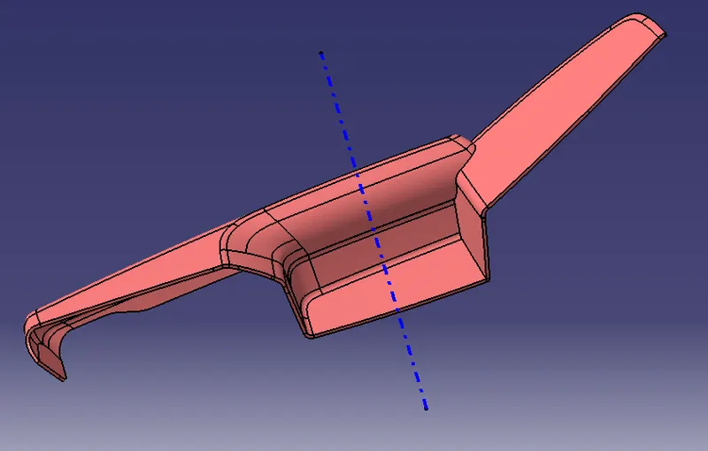
- Draft Analysis of close body / compoonent
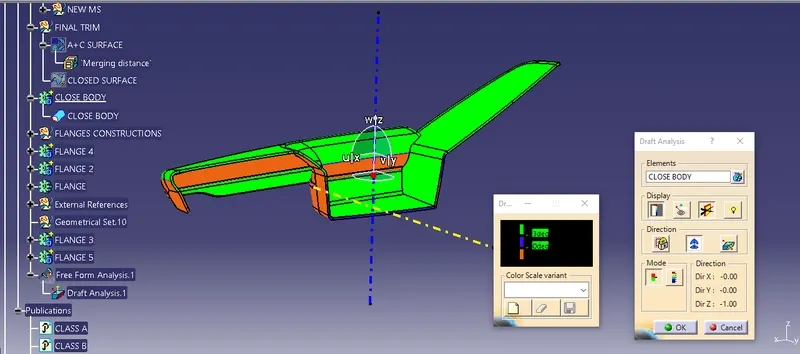
- In reverse Direction
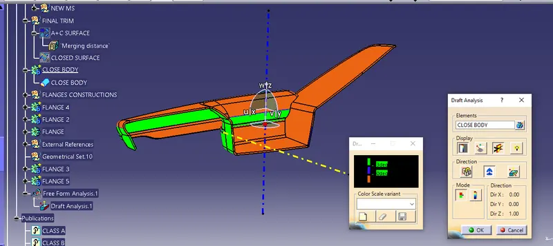
- Draft Analysis With the Side Core Axis / Lifter
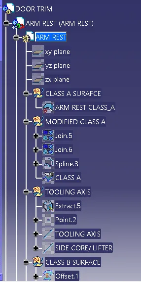
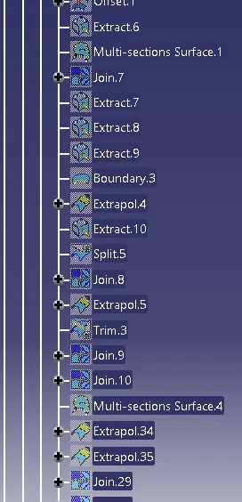
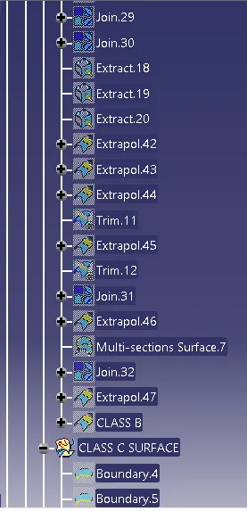
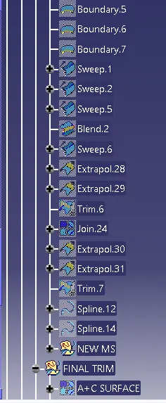
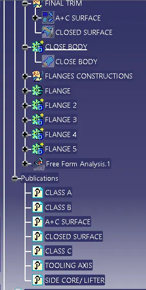
- TREE STRUCTURE OF A ARM REST FROM CLASS_A TO CLOSE SOLID BODY
G] Close Body making :- Close Solid Body/Component.
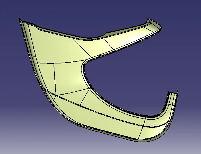
This is a last step for making a Closed Solid Component. Here we change a Generative shape Design workbench into Part design, insert a new body & apply a closed surface commond to make it solid once.
In this way for tmaking another component as a solid body we followed same procedures as explained above.
2] LOWER SUBSTRATE
A] Modified Class A
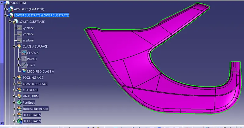
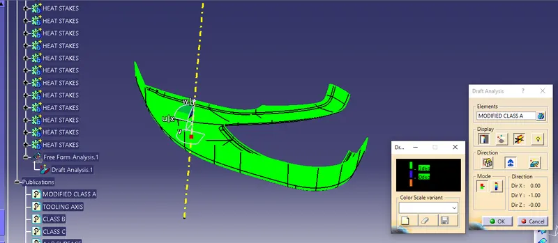
- Draft Analysis Of Modified Class A
B] Tooling Axis Creation
C] Class B Surface
D] Class C surface
E] Final trim & Close surface
A+C surface making a jooin between them
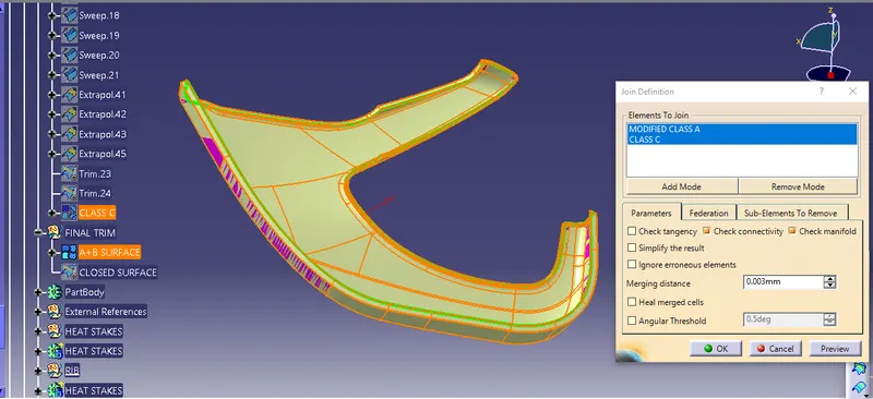
Final trim Between the Class B & A+C surface
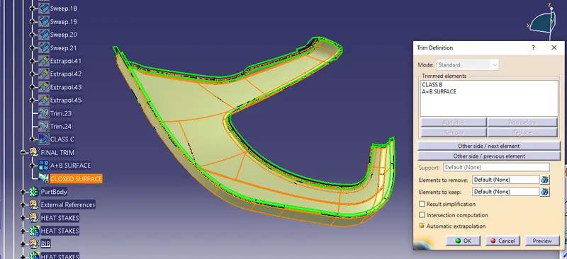
Close Surface of the lower substrate
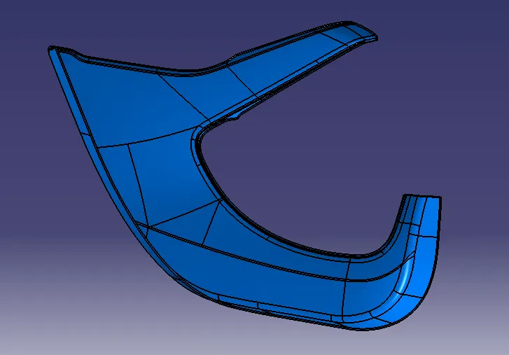
F] Close Solid Body / Component
- Draft Analysis of a solid body of lower substrate
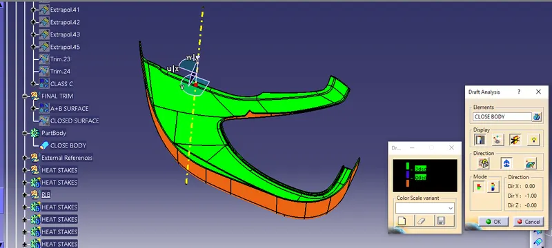
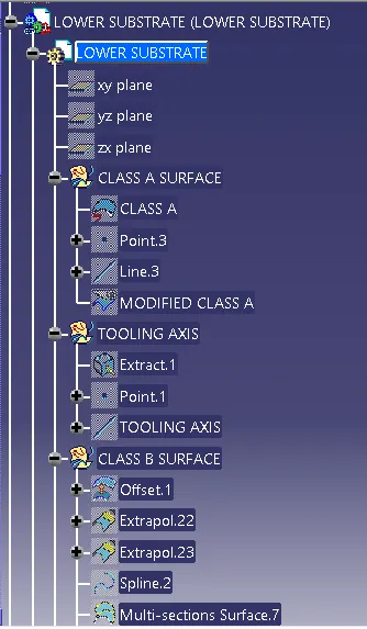
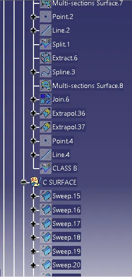
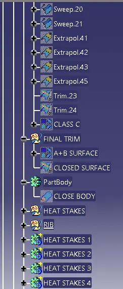
- TREE STRUCTURE OF A LOWER SUBSTRATE FROM CLASS_A TO CLOSE SOLID BODY

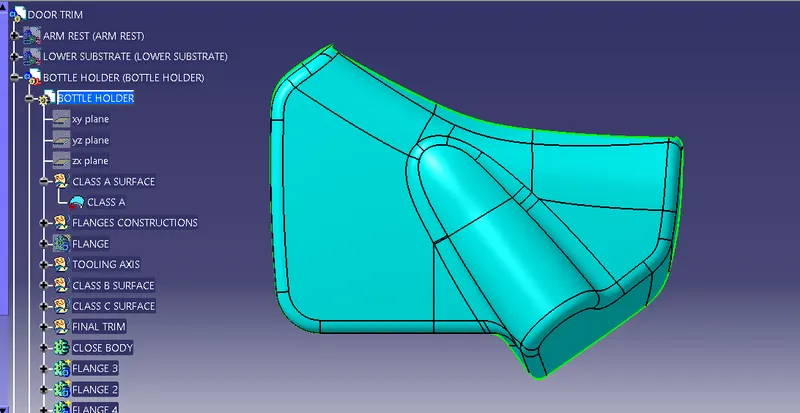
3] BOTTLE HOLDER
A] Class A surface
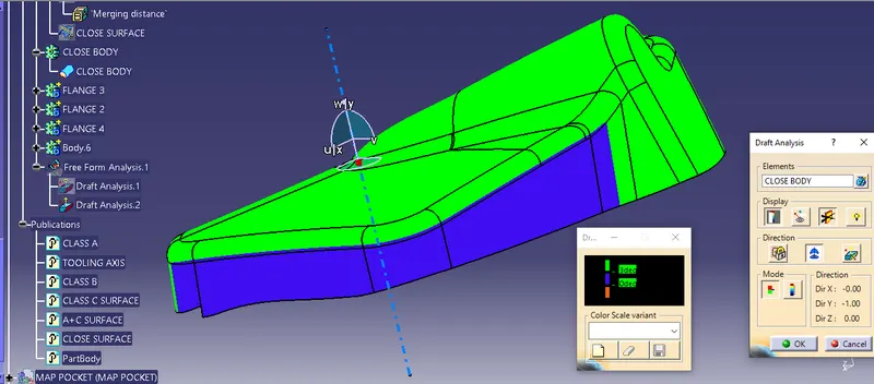
B] Tooling Axis & Draft Analysis
C] Class B surafce
D] Class C Surafce
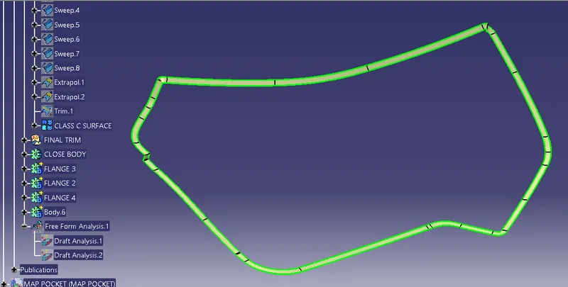
E] Final trim For close surface
- A+C surface maked by the join between Class A & Class C Surface
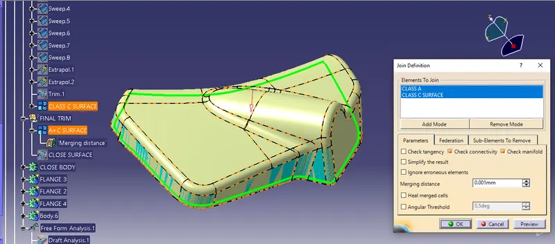
- Final trim with Class B & Surface A+C
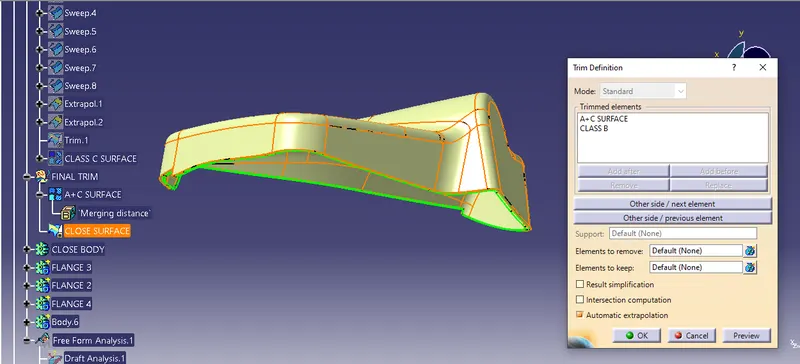
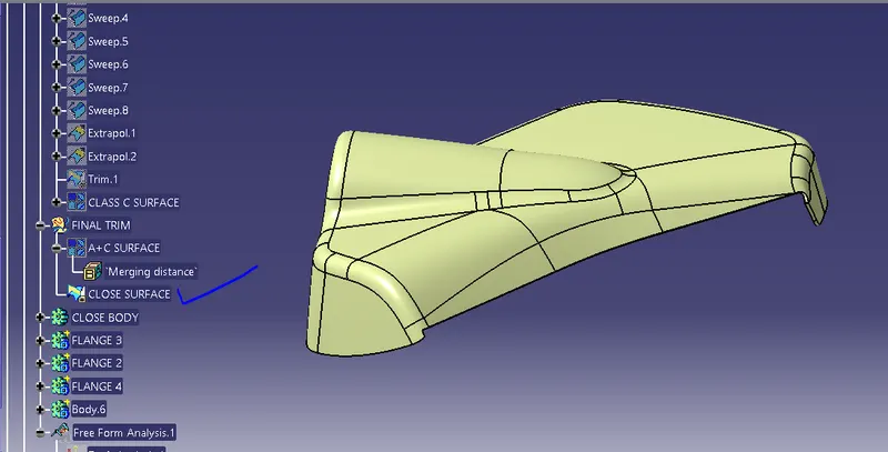
F] Close Solid Surface Body / Comonent
- Draft Analysis Of the solid surface Component
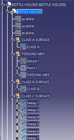
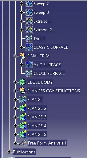
- TREE STRUCTURE OF A BOTTLE HOLDER FROM CLASS_A TO CLOSE SOLID BODY
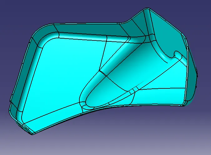
4] MAP POCKET
A] Class A surface
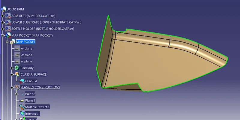
B] Tooling Axis & Draft Analysis
C] Class B Surface
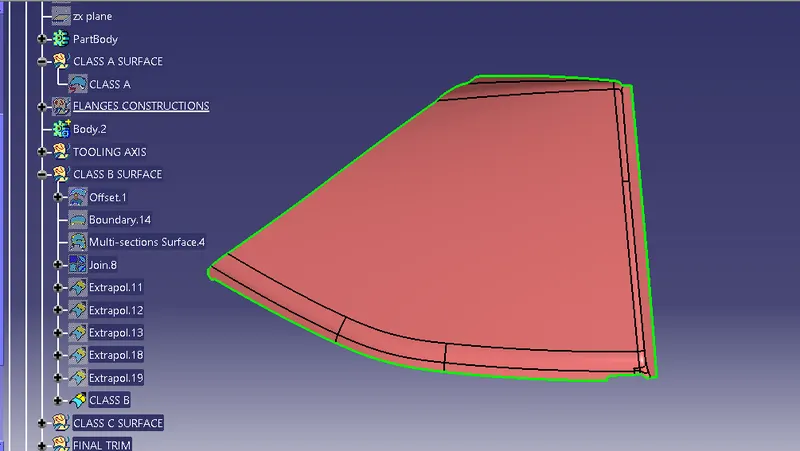
D] Class C Surface
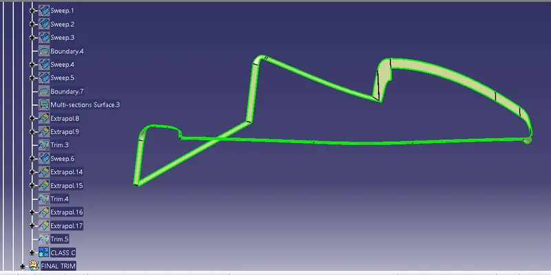
E] Final Trim / Close Surface
- Join Between the Class A & Class C
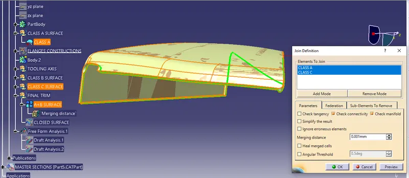
- Final Trim Between the Surface A+C with the Class B Surface
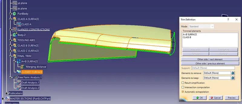
Close Surface
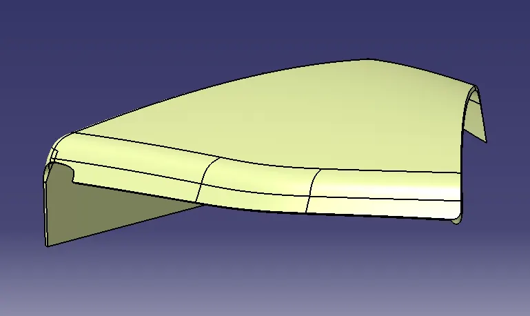
F] Close Solid Surface Body / Component
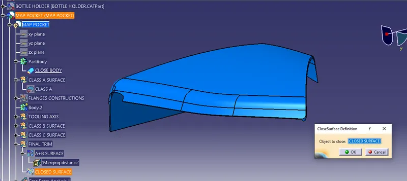
- Draft Analysis Of a Close Solid Body
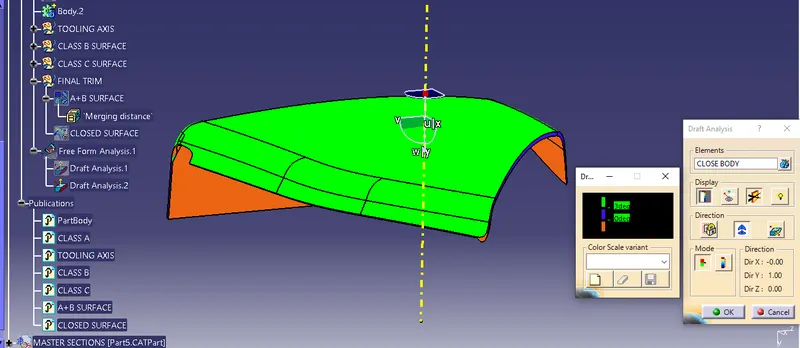
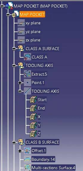
- TREE STRUCTURE OF A MAP POCKET FROM CLASS_A TO CLOSE SOLID BODY
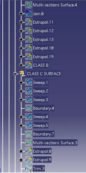
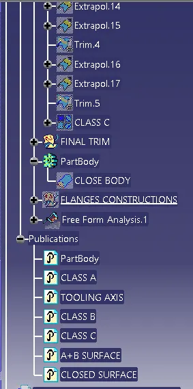
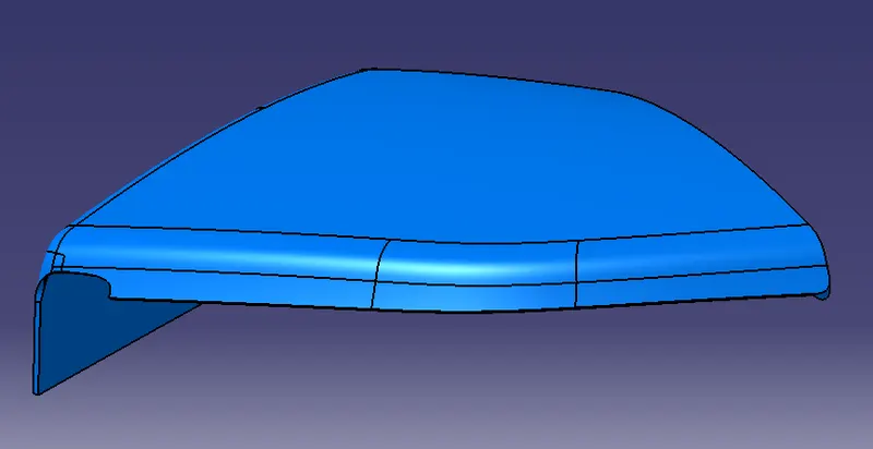 \
\
PROCEDURE_2 :- Creation Of B_Side Features on a created closed solid components as :
- Flanges
- Heat stakes
- Ribs &
- Dog_houses.
At the required position & Design guidelines.
From the above B_side feature creation we take one by one constructions as well, First need to create a Flanges, Heat Stakes, Ribs & Finally Dog House. With the proper draft analysis.
A] FLANGES CREATION :-
A flange is a projecting ridge, rim, collar or ring on an object such as a column, beam, pipe and so on that provides additional strength or stiffness or additional surface area for the attachment of, or to, another object.
The Steps are followed foe the Flange creation.
- So for the Flange creation we take a referance from the provided master section. From the master section the first step is to create a points for the proper plane as a sketch positioning.
- After the plane got we need to get a multiple extract of the C surface of a refered part. Then we need to take a boundary over where the flanges we need.
- Then Create a intersection with the Created plane & Extracted surface. Here we got a intersection line , from which we need to start a sketch of the Flange.
- From the bottom point of a intersection line we start a sketch referance of a master section & complete a sketch. After getting a sketch We need to take a sweep is there. With the referance surface profile select a sketch & profile as a boundary of the Class C Surface.
- After getting sweep we need to make a thiickenned to it with 2.5 mm from the master section width. And get a split with Similar lengths. Finally getting a Flange.
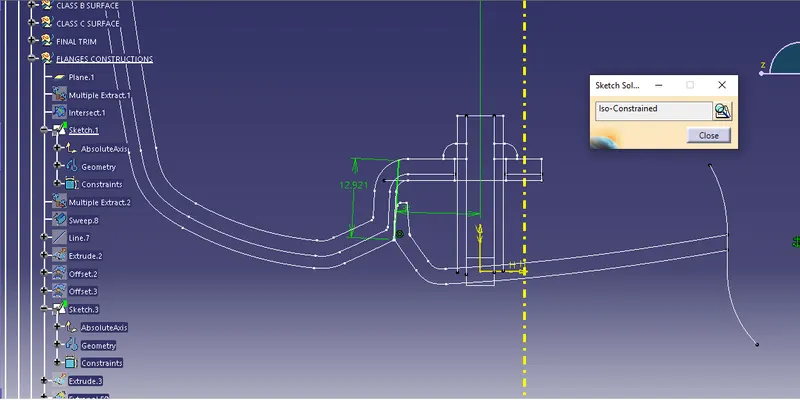
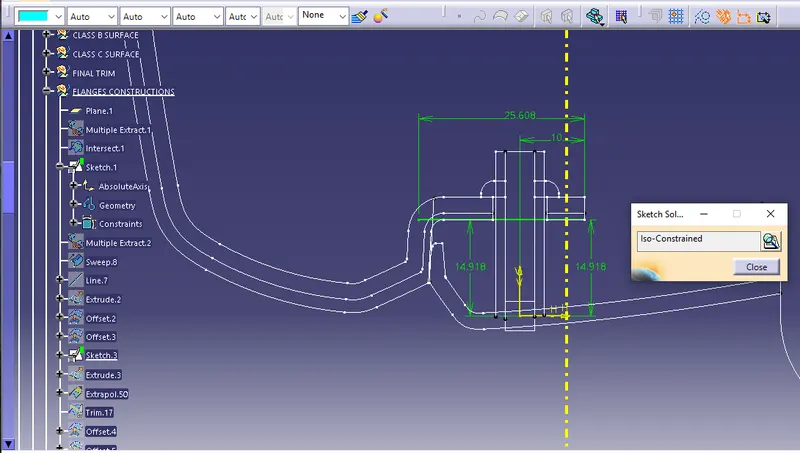
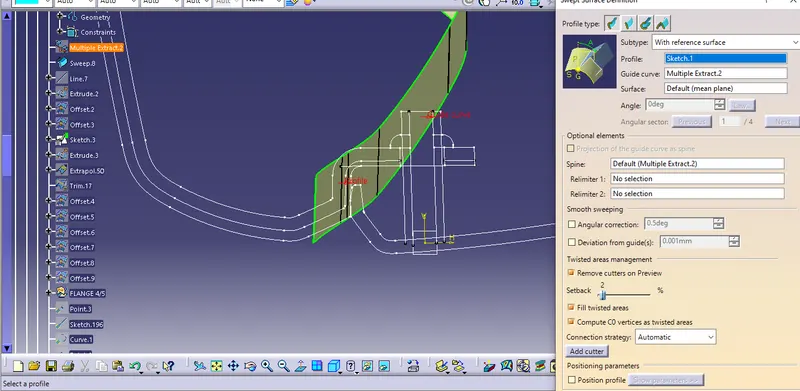
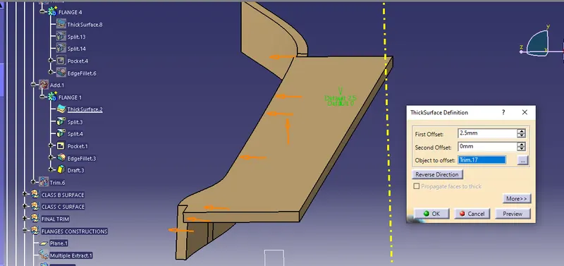
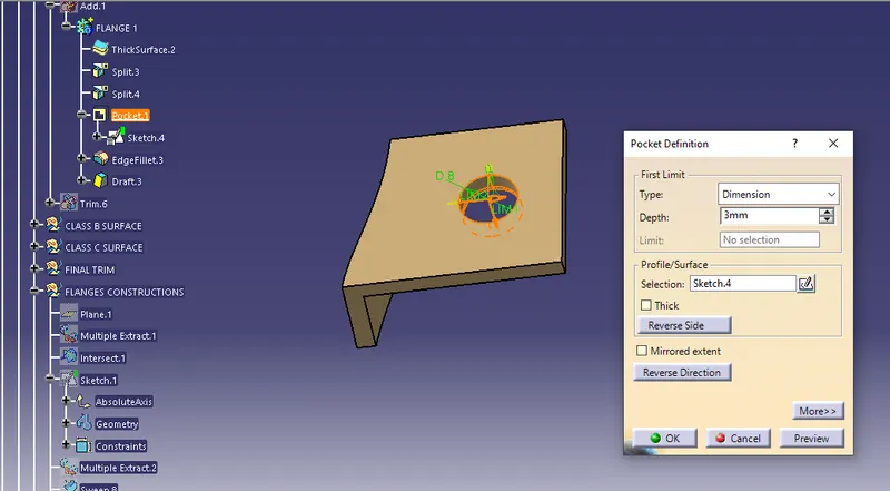
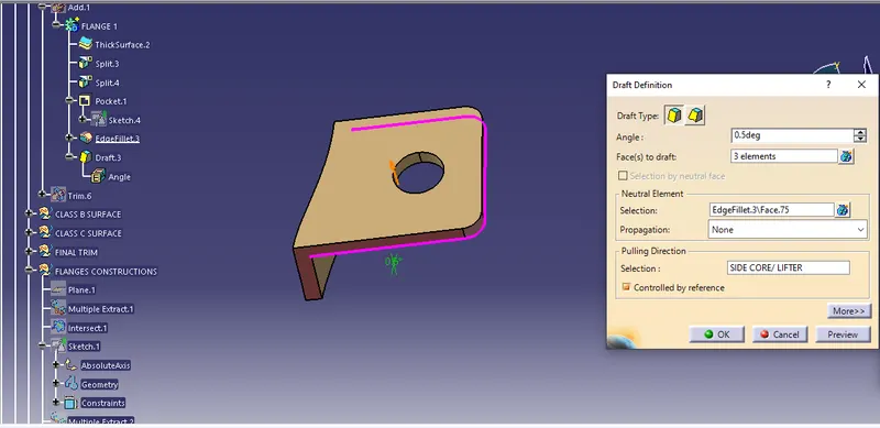
In this way the Flanges are created to the Arm rest & remaining parts also with the master section & By the referance of a Extracted C & adjecent surfaces as well.
- Draft Analysis of a Flanges.
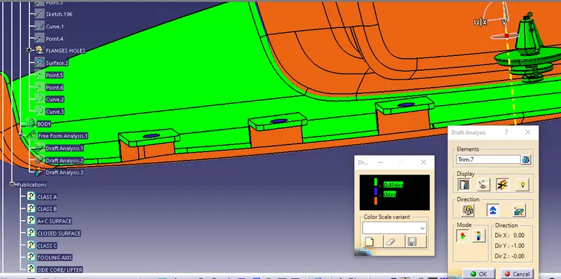
B] Heat Stakes Creation :-
Heat staking also known as thermoplastic staking is the process of joining two dissimilar materials together. In heat staking we use local heating and cooling to raise the temperature of plastic components and allow plastic reforming to be carried out. This reforming can be used in a wide variety of applications.
The heat Stakes are created on all over the lower Substrate part. Here we only one parent/original Heat stake are created & transfer all the remaining reuired position, by creating the points spacing & instances by the desired distance maintained.
The steps of a heat stakes as taken follows:
- Here we need to create a First heat stake by the help of a Mater section,The same procedure are followed like a flanges created.
- here also we need to create a point & plane for the sketch creation, after the sketch has complete we need to Pad it Desired height.
- But the Draft angle also need to provide.
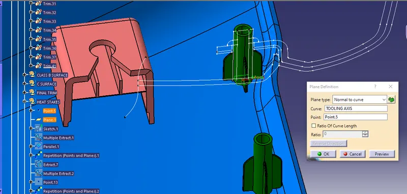
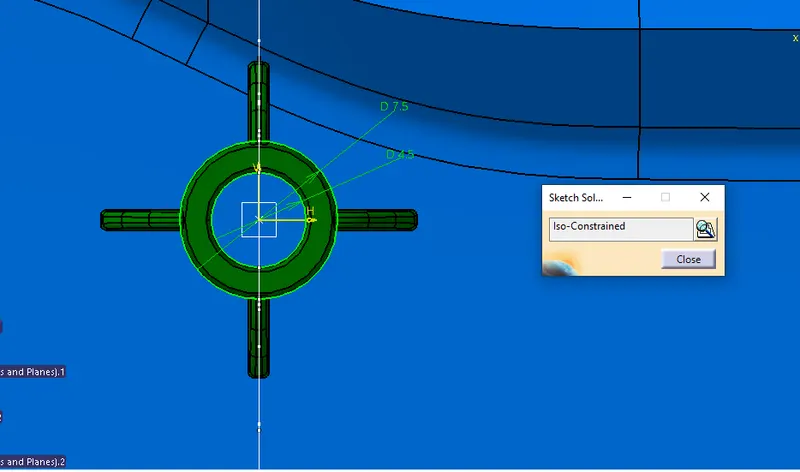
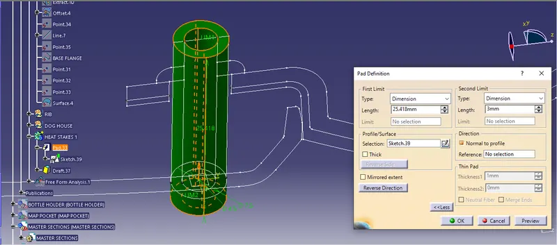
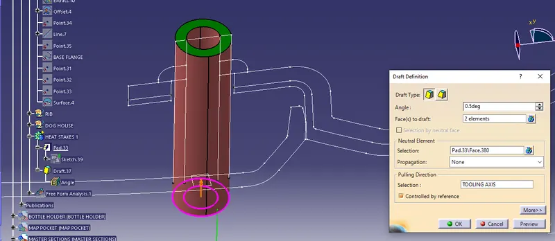
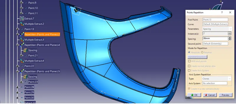
In this way the Heat Stakes are transfer from pont to point are created to whole part desired position as well.
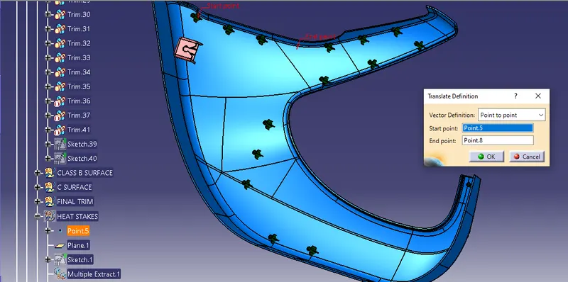
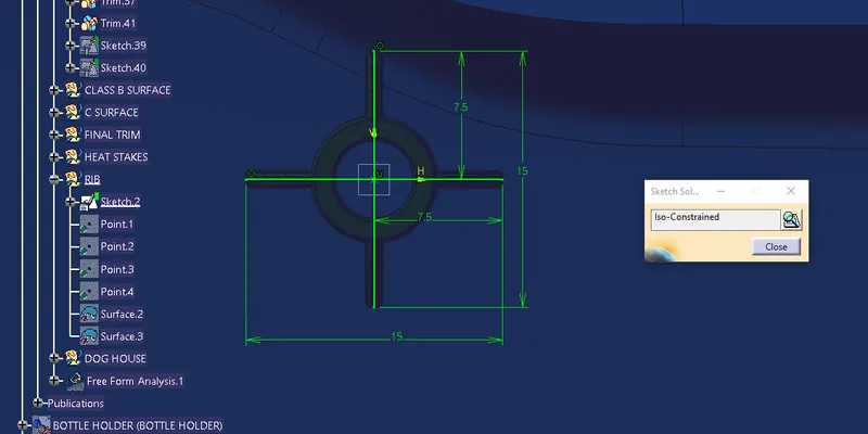
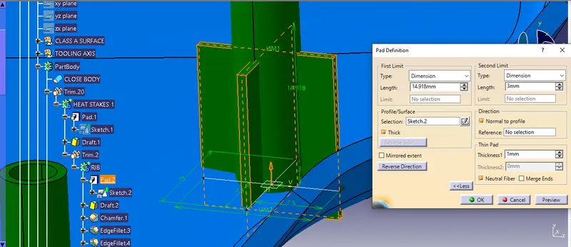
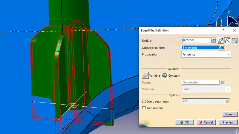
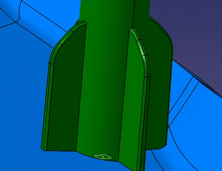
C] Ribs Creation :-
Ribs are thin, wall-like features typically designed into the geometry of a part to add internal support to walls or other features like bosses.
The Ribs are created to the support for the Heat stakes & Resting fittment support for the Flanges. The Steps are followed as follows for the creation of Ribs:

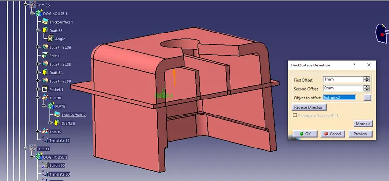
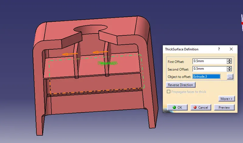
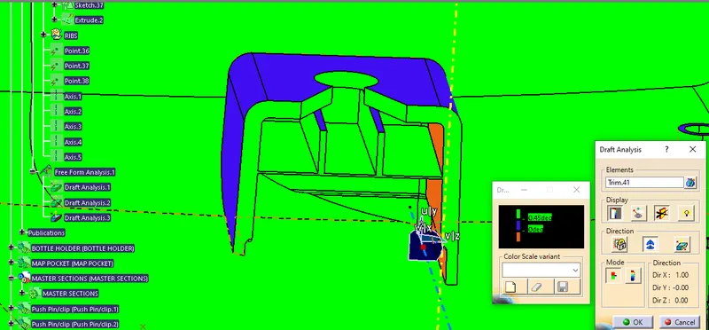
D] Dog_House reation :-
- The steps are followed for the Dog_House as follows:
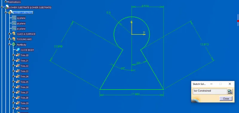
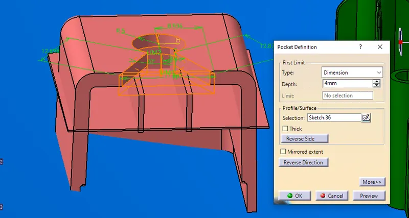
- We need to first get a extract of the desired location of where the Dog_house has creation. Here first need to create a point & plane for the sketching of a Dog_House.
- After the sketch we need to take a sweep there, with an Draft angle 1.5 Degree. Close the Top surface by applying the Extrude creation the line or make a offset & split that already base extracted surface.
- Then extrapolate the surfaces & make a trim. Finally make a thickned to it with the 2.5 mm as part thickness. After that create the B & C Section at the bottom to 0.4 * Thickess of the Dog_House.
- Then Make a Base Plate & Ribs to get strengthed to it. For lastly for the push Pin locationn we need to create a circular slot is there, so create a slot sketch & maked a Pad applied the Boolean operation as well.
- In this way we have created the Dog_House & transfer it in 2 again location as point to point creation for the constrained purpose.
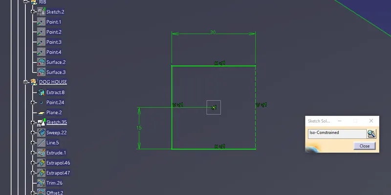
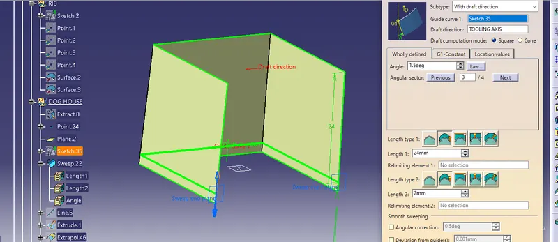
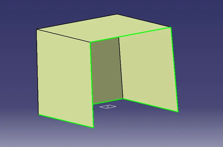
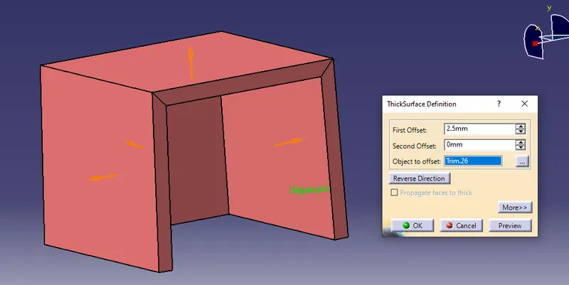
- Complete Dog_House & Draft analysis.
PROCEDURE_3 :- Placing the push pin over the Dog_house (final step)
Push pins - Push pins are used for joining one component to another. These are basically attached to the dog house
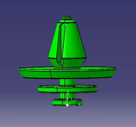
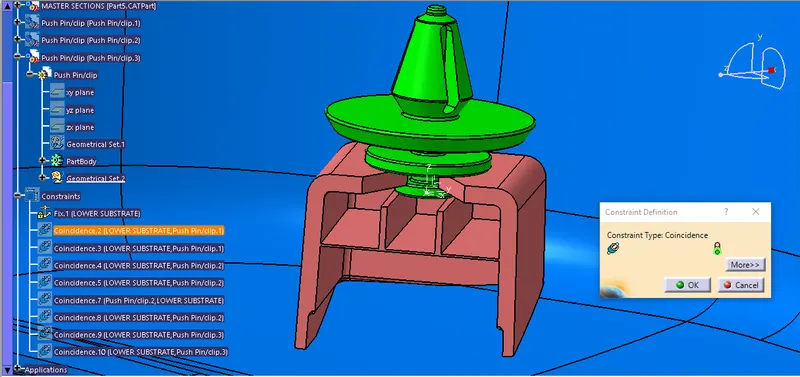
The push pin are are basically used to join the components within thr Dog house. Thus we need a Dog_house, so we have already created the 3 Dog_houses over the Lower Substrate component. Also we have provided one Push_pin in the challenge/Project lynk. We have added it in a Assy Door Trim Product file. We here make a copy & paste it 2 times hence here we need a 3 Push pins for the 3 Dog_houses as well. First we make a fixed constrained tothe part for which the part can't move & dissable. Then we make a coinside constrained. So the coinside constrained applying before we make a axis to the centre of a Dog_house. Then again apply the coinside constrained to the flat surface of the Dog_ house & push pin matching 2nd rim.
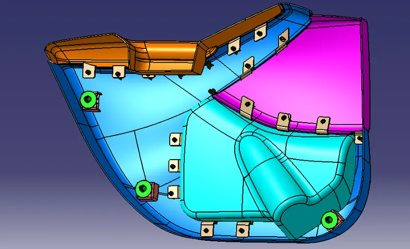
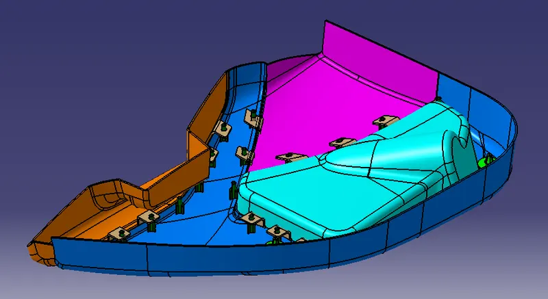
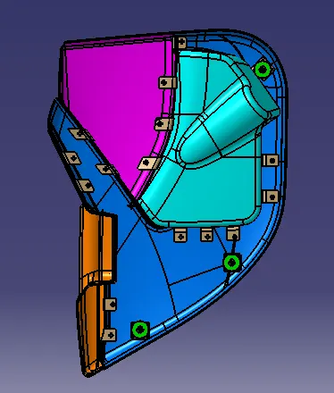
- FINAL ASSEMBLY OF A DOOR TRIM WITH ALL ENGINEERING FEATURES
CONCLUSION:-
In this way we have maked a complete Door Trim Assembly by the provided Class_A surfaces & master sections as well, Also applied a B_Side features on it with the design guidelines standard. The Draft Analysis is done all over the components & B-Side features. Here we have attached a multiple snaps & created the proper report on it. The Tree_structure maintained sequencely. Finally browse the Assembly product file as well.
Thank You.