Week 12- Final project
Aim:
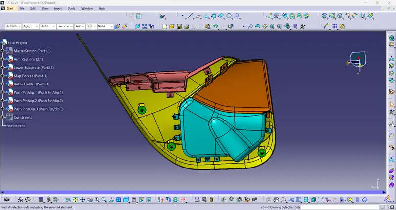
To create a CAD model of a side door trim panel from given class A surface.
Objective:
- a) Creation of side door trim panel from given class A surface. Apply thickness to it and use attachment
- b) Creation of flanges and heat stakes from given master
- c) Creation of doghouse and various attachment features using industry standards
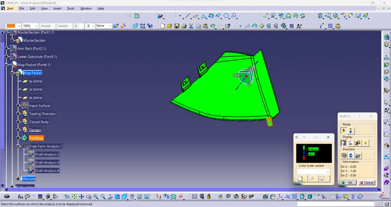
- d) Performing draft analysis and ensuring the features and surfaces clear it .
Introduction:
The ten stages in automotive product life cycle development are listed below.
1)Concept sketch
2) Styling class A
3)Feasibility check
4)Concept validation
5)New product design
6)Product development
7) Prototyping
8)Design validation
9)Pilot production
10)Mass production
From the above stages, it is in stage 5 that a new product is developed and validated from class A surface. The objective is to design class B and class C surface from given class A surface and create a solid body from it using software like CATIA V5, UGNX taking into consideration the draft analysis which makes the component suitable for production using injection molding process.
Given below is the procedure to create a new plastic component from given class A surface.
1) Creation of tooling axis
2) Creation of class b surface
3) Creation of class C surface
4) Creation of closed body
5) Draft Analysis.
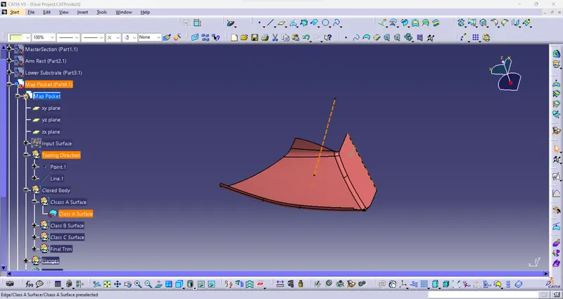
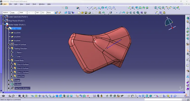
Draft analysis is done to ensure that the designed part is manufacturable based on the draft conditions applied. It is done to ensure the proper ejection of the component from dies (for metals) or molds (for plastics). The basic idea is to ensure that the tooling axis must be created in such a way that it has no parallel surface profiles of the component so that the ejection of the components can be ensured. Tooling axis is the axis along which cavity and core are closed and opened.
The main components of the interior door panel of a car consist of the following parts.
1) Arm rest
2) Lower substrate.
3) Map pocket (Consists of upper and lower part)
4) Bottle Holder.
Givan Class A Surface:
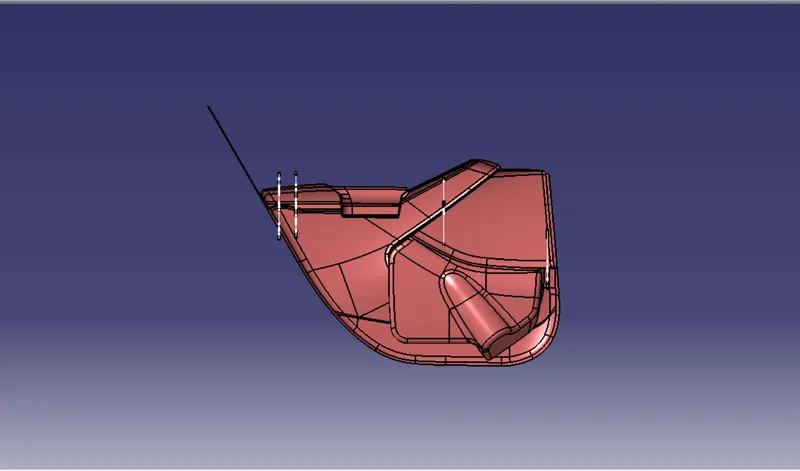
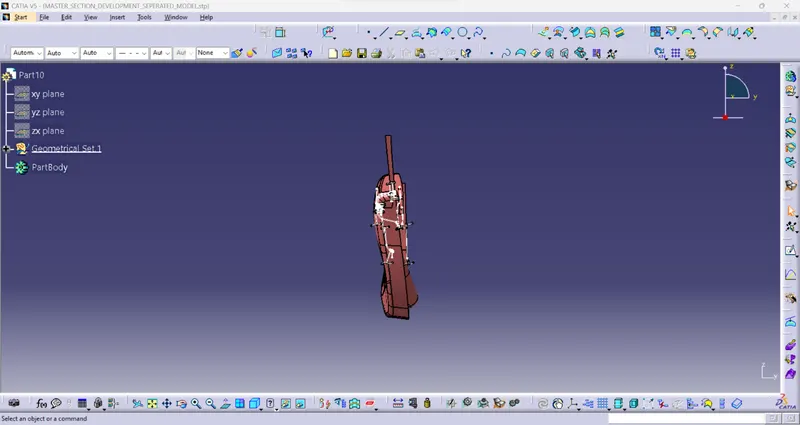
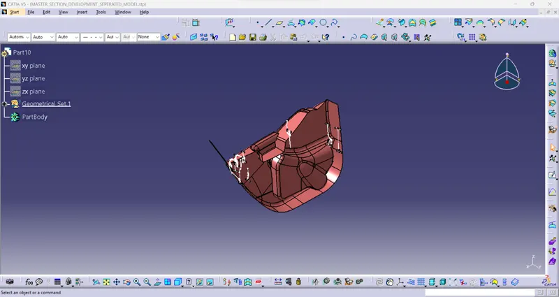
Create a product file and copy each component into different part files and name them accordingly.
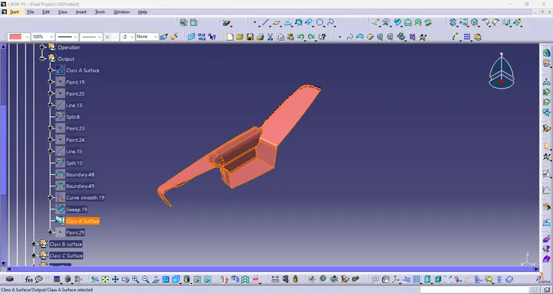
- Arm Rest:
Re-creation of Class A Surface using with given input:
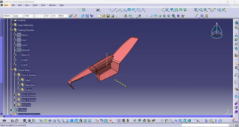
Tooling Axis And SideCore Axis:
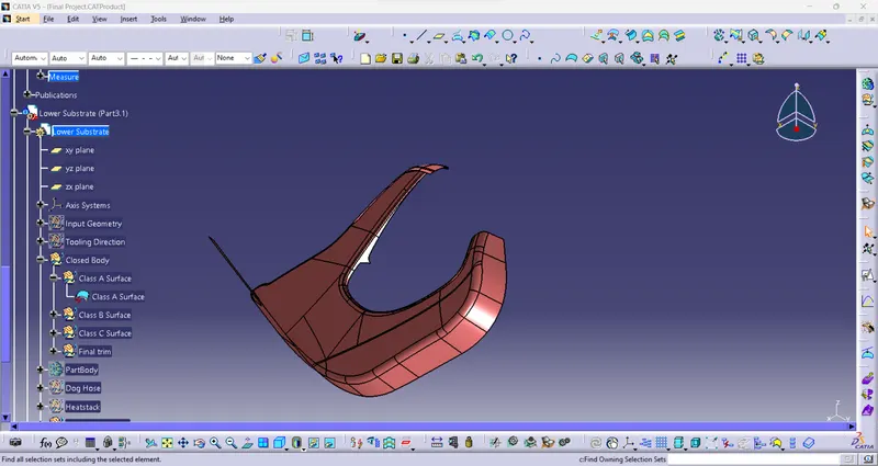
2. Lower Substrate:
Class A Surface:
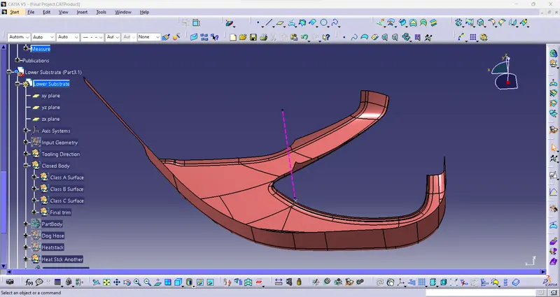
Tooling Axis:
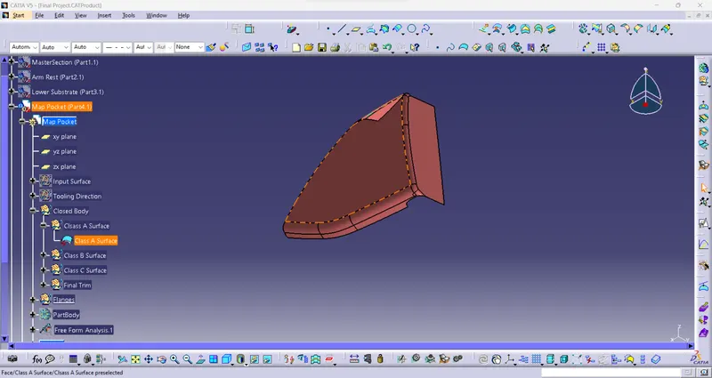
3. Map Pocket:
Class A Surface:
Tooling Axis:
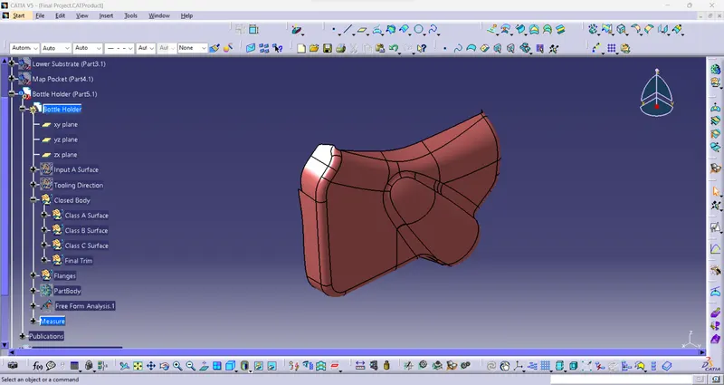
4.Class A Surface For Bottle Holder:
Tooling Axis:
1.Arm Rest Class B Surface:
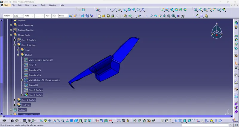
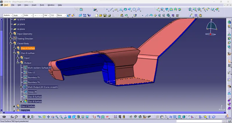
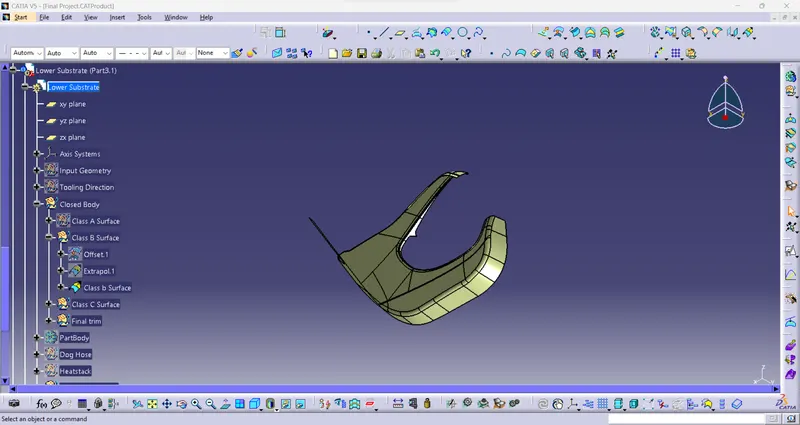
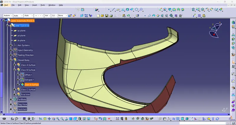
2.Lower Subtrate B Surface:
3.Map Pocket B Surface:
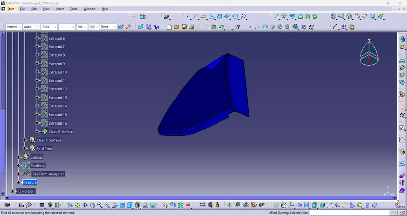
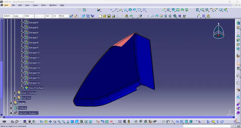
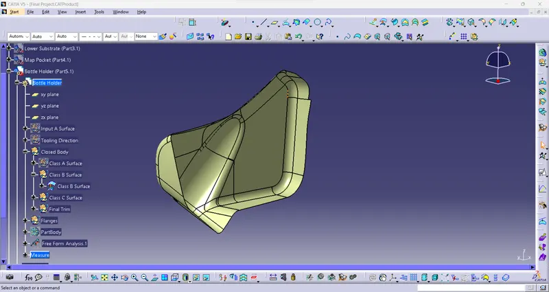
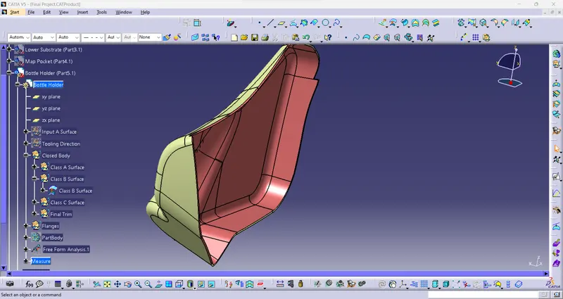
4.Class B Surface For Bottle Holder:
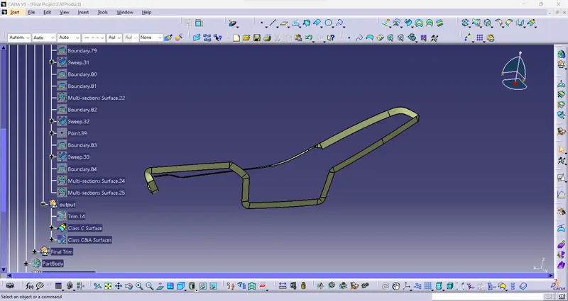
1.Armrest C Surface (Make C Srface it is used to make it as a closed part forthe every product):
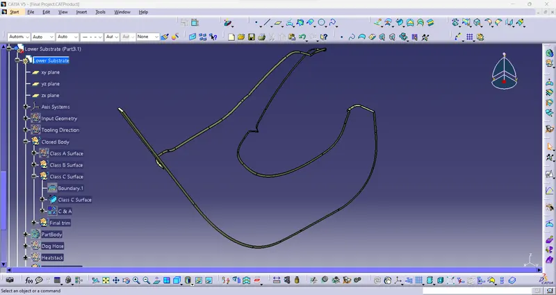
2. Lower Substrate C Surface:
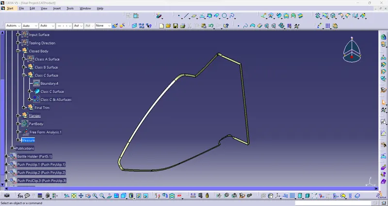
3.Map Pocket C Surface:
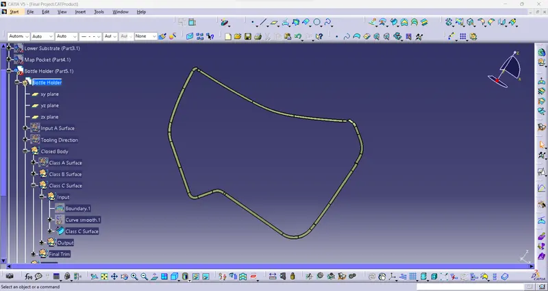
4.Class C Surface For Bottle Holder:
1.Final Trim:
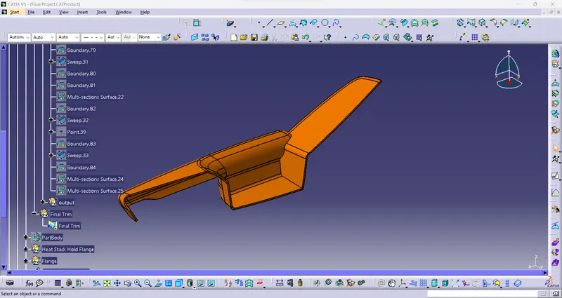
2.Final Trim For Lower Substrate:
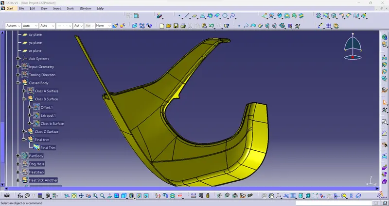
3. Final Trim For Map Pocket:
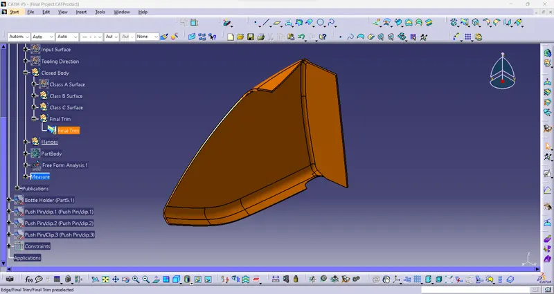
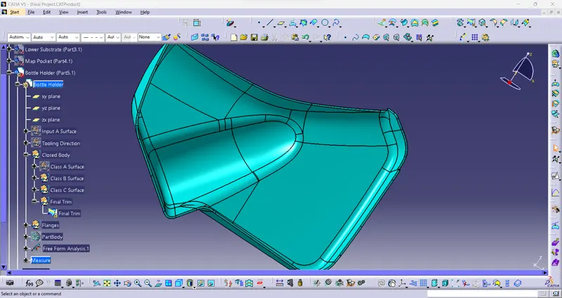
4.Final Trim For Bottle Holder:
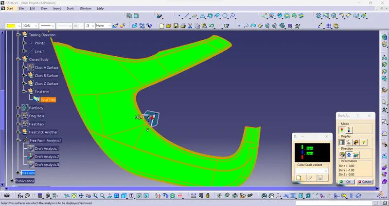
Draft Analysis:
1.Armrest:
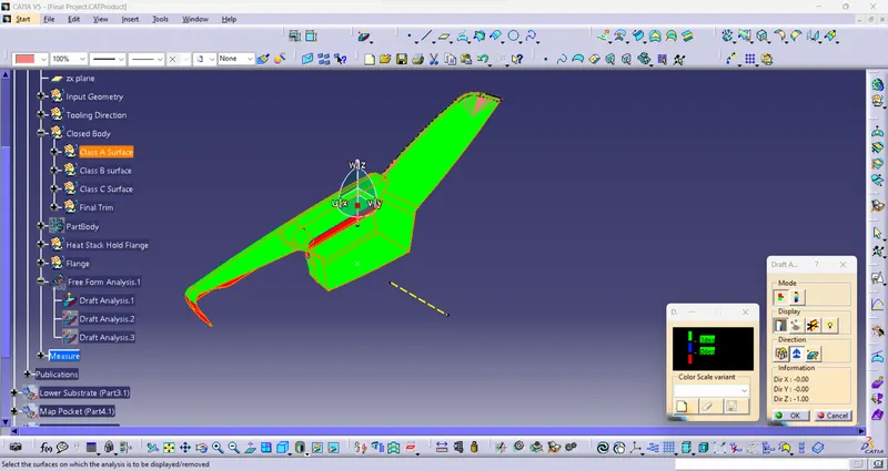
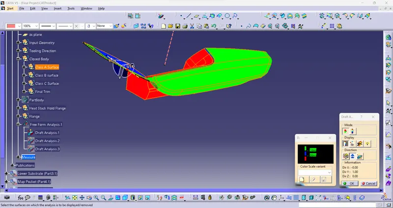
Closed Body Draft Analysis:
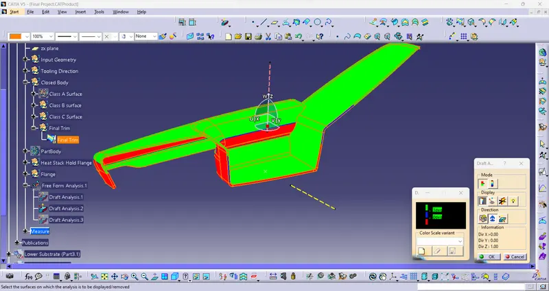
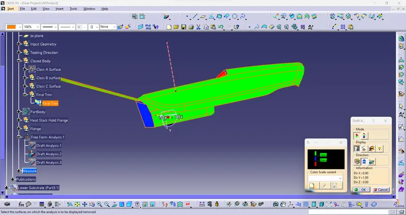
2.Lower Substrate:
Class a Surface:
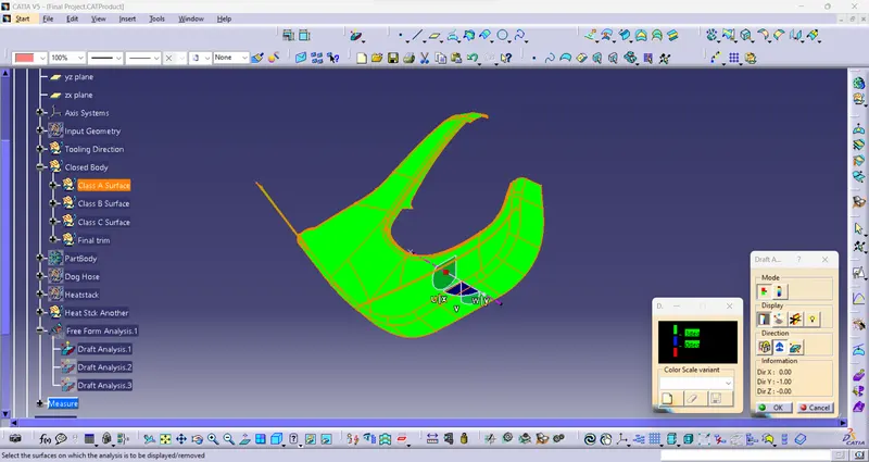
Closed Body:
3. Map Pocket:
Surface A
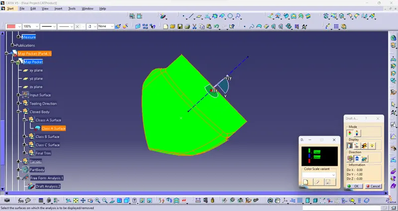
Closed Body:
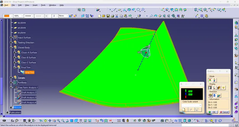
4.Bottle Holder:
A Surface
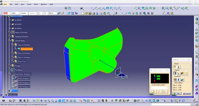
Closed Body
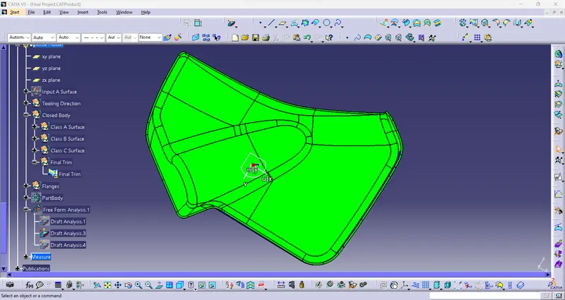
Attachment Creation or Engineering features:
1. Rib
2. Heat stake
3. Doghose
4. Locators
RIB
Ribs increase the bending stiffness of a part. Without ribs, the thickness has to be increased to increase the bending stiffness. Adding ribs increases the moment of inertia, which increases the bending stiffness. Bending stiffness = E (Young's Modulus) x I (Moment of Inertia). The rib thickness should be less than the wall thickness-to keep sinking to a minimum. The thickness ranges from 40 to 60 % of the material thickness. In addition, the rib should be attached to the base with generous radiusing at the corners. They are thinner than primary walls and are used to support these walls, as well as bosses, by running perpendicular to these structures. Ribs are often used to replace thick wall sections to avoid sink marks, warp, and voids.
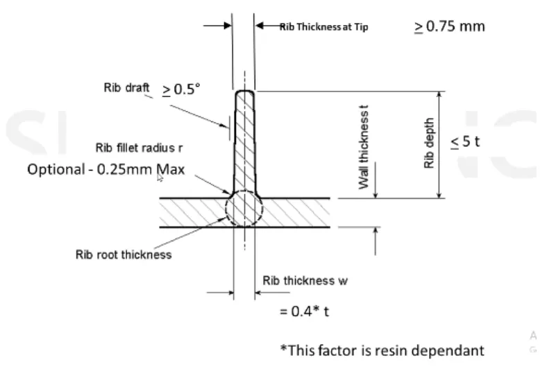
HEAT STAKE
Heat stakes ate generally screw boss line structure without tread in it used to join to part each other by thermal staking. heate stake is go trough the conter part from its parent part and at the tip its heated so it can weld over the conter part and these two parts are get assembled with each other. ther is no such a design gudlines for the heat stakes but yes design it with the
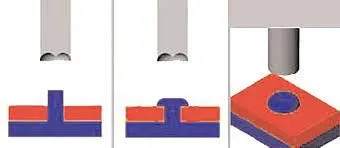
DOGHOUSE
Dog house is an engineering feature used in plastic trim design. Dog houses are used as supporting feature. Sometimes other engineering features like snaps; locators etc. are mounded on them to increase their
strength.
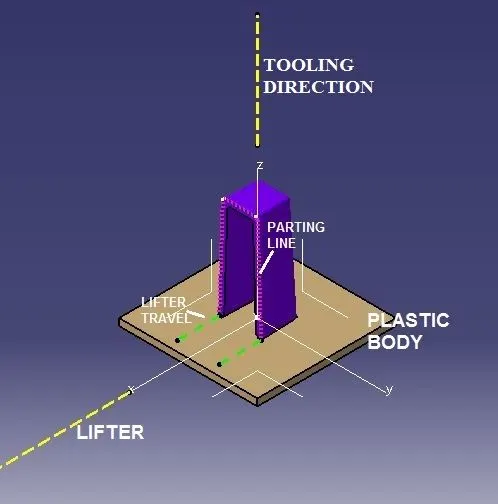
Given Master Section Using Armrest Flanges:
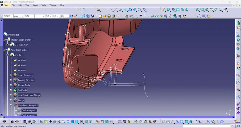
Map Pocket Flanges
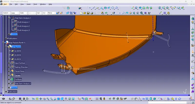
Heat Stack and Locators and DogHouse In Lower Substrate
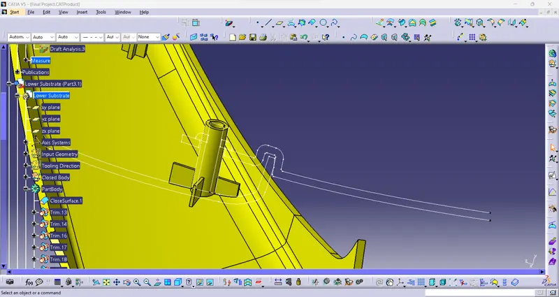
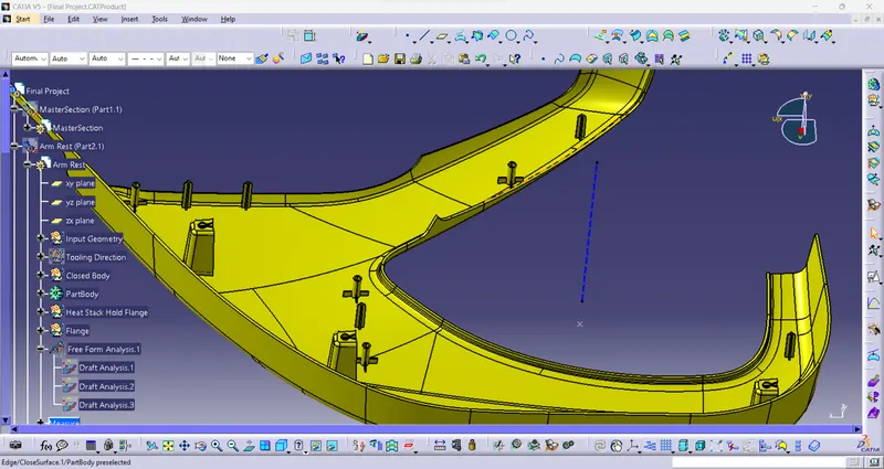
Bottle Holder Flages
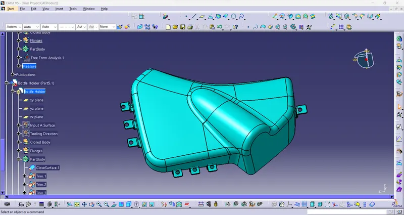
Draft Clear For Attachment Creation:
1.Armrest
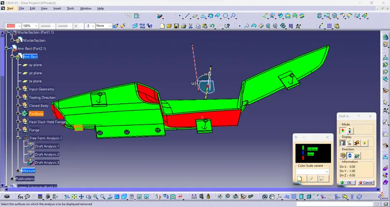
2.Lower Substrate
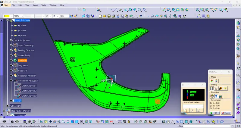
3.MapPocket
4.Bottle Holder
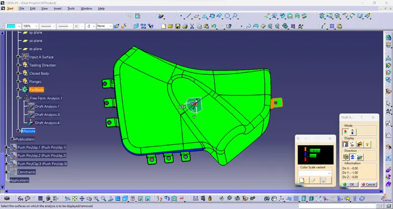
Final Output: