Week 12- Final project
Here i am presenting the report for the final project of door trim panel.
- The class A surfaces are given as the input,by using the class A surface i developed the door trim.
Here i am attaching the all the class surfaces below
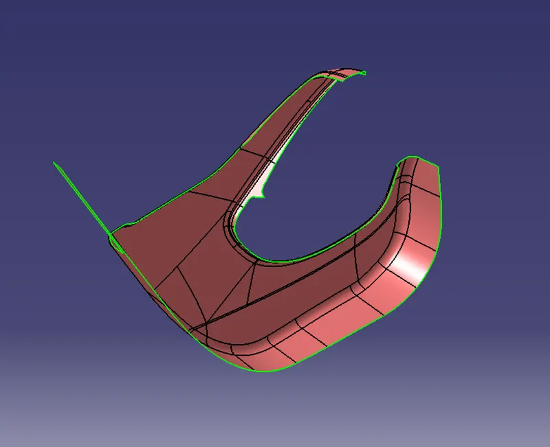
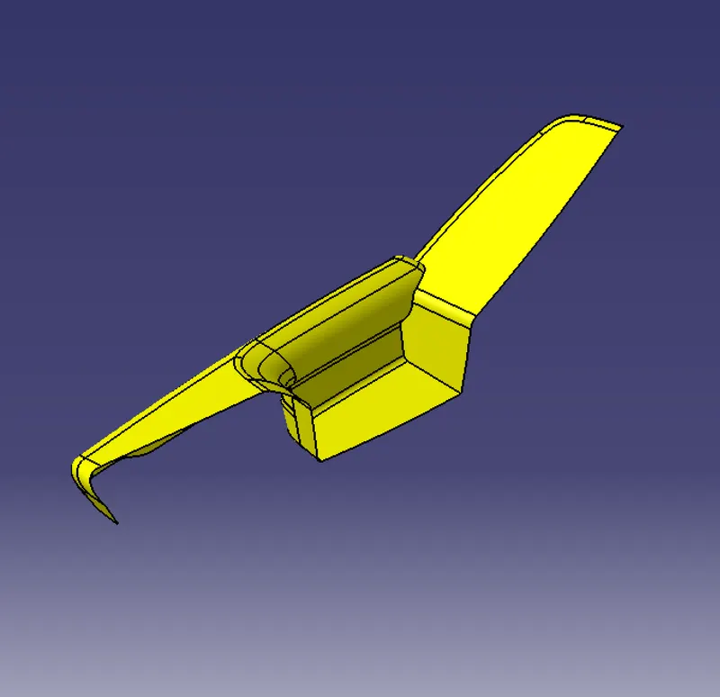
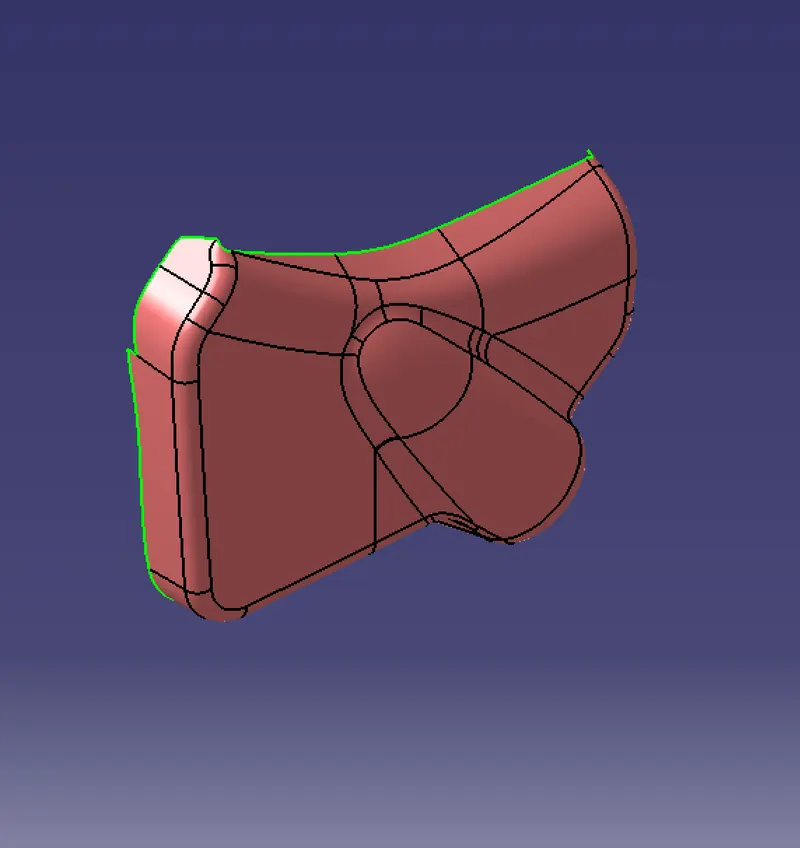
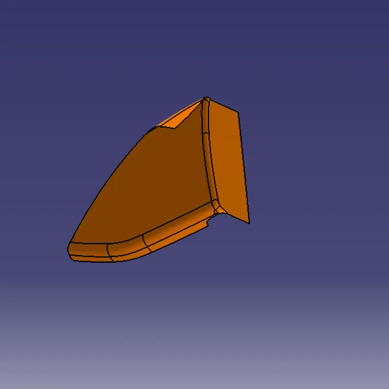
- The intial step i took is to created the tooling axis on each and every surfaces, since they manufactured separately.
- After creating the tooling axis the tooling analysis must be carried out to check whether the surface is manufacturable or not,if there is no required draft we must be informed to the design team,In this case all the drafts are sufficient,proceded further.
SURFACE B CREATION: (each part follows the same procedure until the creation of the closed surface)
- B surface can be created by using the given class A surface,by using the command called offset surface for the given value,the offset value gives the thickness of the part which needs to be created, i found the thickness value from the given master sections.
- After applying the offset surface, All the edges will not created and few edges will missout and those surfaces are created by using the mutiple tools called multiple extact ,extract boundary,extrapolation,trim,split,etc.
- We need to make sure there is no gaps or any boundary which is inside of the surface , the boundary must be shown at the edges only. here i am attaching few images to referance of B surfaces.
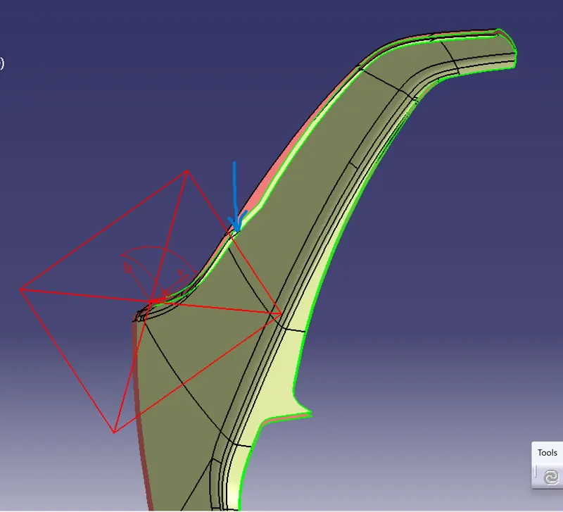
Likewise all the B surfaces for all the given surfaces are created with the refarence of master section.
SURFACE C CREATION: (each part follows the same procedure until the creation of the closed surface)
- C surface is created on the edges of the surfaces which is usually on the class A surace,which we generally say as A+C surface, This surafce can be created by using the command sweep.
- If the surface edge is parallel to the tooling axis we must give the draft towards the outside because the side faces needs to have some draft as the production demands the draft angle.
- Usually the draft angle is provided as 3deg,after creation of c surface alone and get the closed surface at all the edges ,when trim operation ocuurs the two surfaces will get joined.
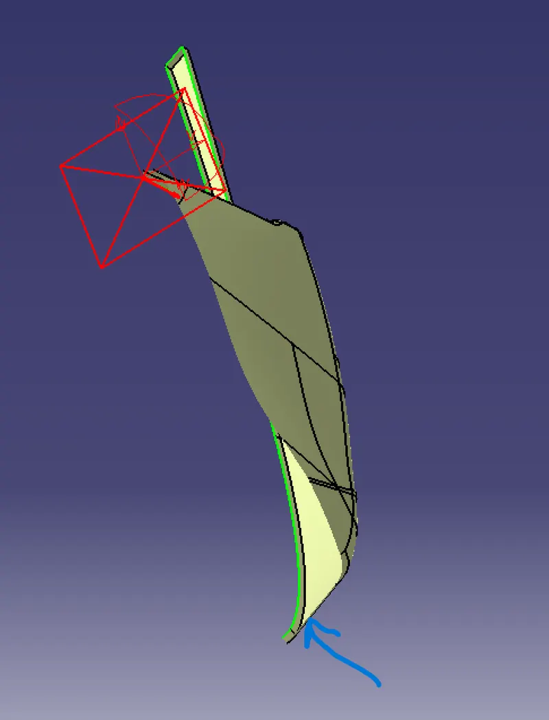
The procedure repeats for all the parts to be created,to create the closed surfaces the class B must be extracted with some miminum value to trim with the surface A+C , The result whichb we get from the trim of A and A+C is closed surface.
Here i am giving the referance of all the closed surfaces.
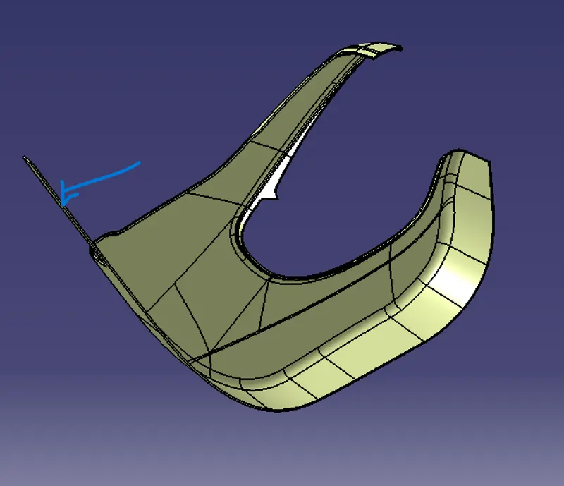
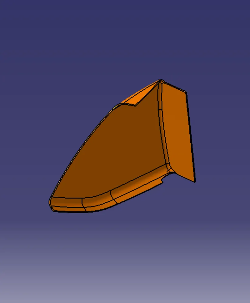
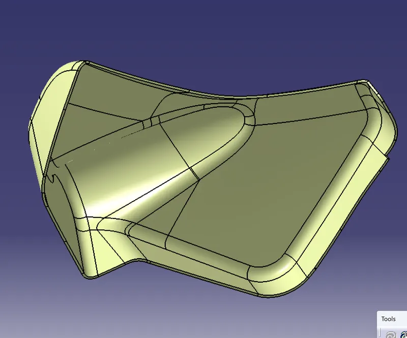
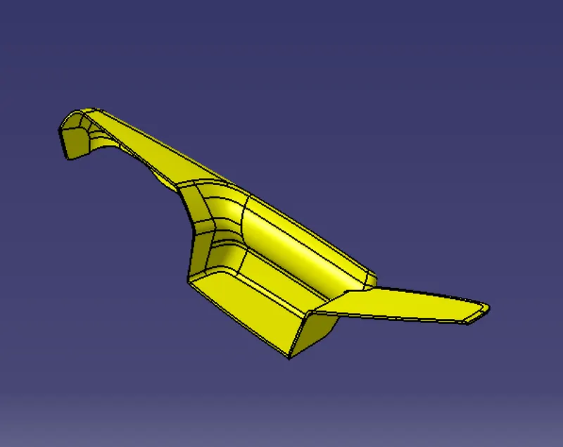
- To create the solid part, changed the workbench to part modelling,and inserted the new body and define it and use the close surface command to create the solid from it.
ASSEMBLY WORKBENCH(PRODUCT):
Created the product workbench, and added the parts into it by using the import existing command which is already saved it.
Added all the parts into the assembly workbench,and showed it below
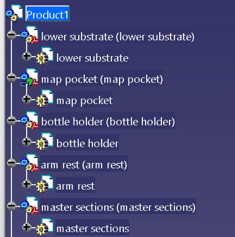
And also added the mastersection in order to refer them.
B SIDE FEATURE CREATION:
Now the approch is towards the creation of the B side features such as Flanges, Heat stakes,Ribs,Dog houses,etc
Flanges :
Flanges are used to connect the parts of different which together meant a door panel.
The creation of flanges can be done by using the master sections, master sections can decide the position,length and width of the flanges.
By refrering to the master section i have created the planes by using the three point method.and created the sketches and used extract and sweep method to create the profile and gave thickness to it by creating the body.
No of flanges can be decided by the designer,considering the design rules and model currently created.Few of the images of flanges are attached below.
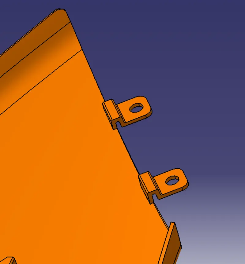
The holes on the flanges are need to be created to allow the heat stakes to emerge from the flanges.The same method is followed for all the parts which requires the flanges.
HEAT STAKES:
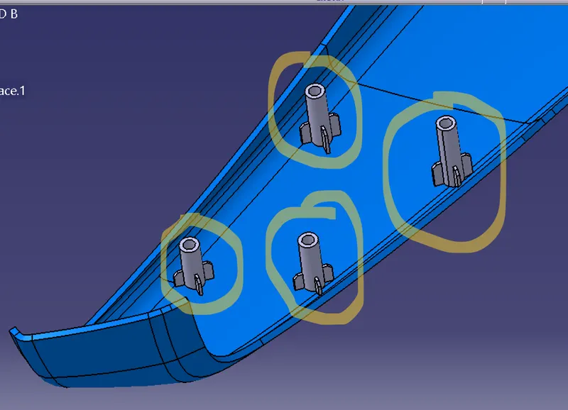
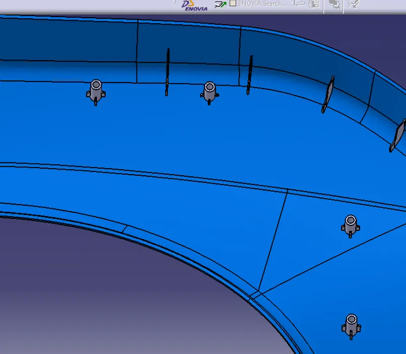
Heat stakes are basically circular in profile, they meant to fix the parts each other, the circular pad will mounted into the flange hole, the heat stakes will be heated and it turn to the fixture.
To make more strong the ribs are provided for each hest stakes, the drafts need to given to make the part is productable.
The images are attched below, the lower substrate is choosen to make the heat stakes on it.
RIBS:
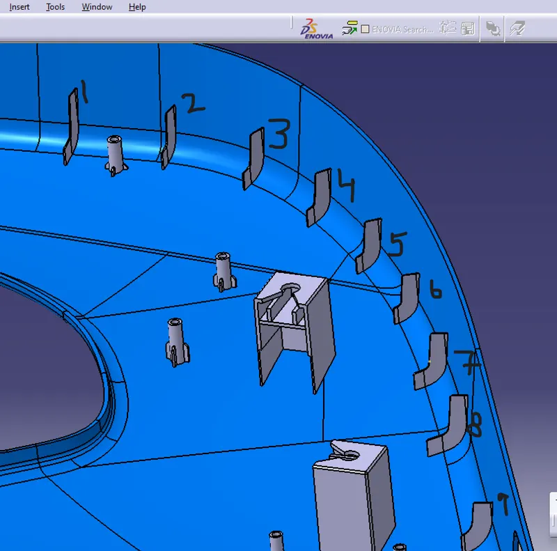
Ribs also a very important feature for any part, ribs will make sure the part not to bend at load conditions.the spaces between the ribs are atleast to be 50 mm as per the design regulations.
DOG HOUSE:
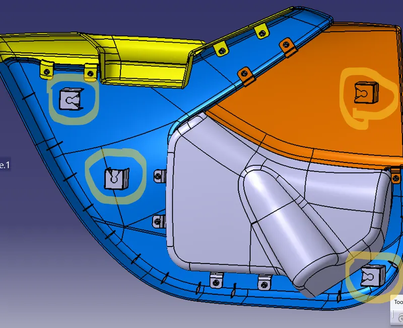
Dog house is the main feature to fix the outside sheetmetal and the inner parts,by using the push pins.The shape of the dog house is created in such it mounts the push pin and side sheet metal.
it is created on the B side of a part,number also depends on the part surface,and also position, the position must be place at all of the corners where it can hold securly.
it is created based on the design standards,the draft must be provided to clear the draft analysis,and make it does not affect the production.
The lifter axis is created to make the production easier,where the main tooling axis not clear the draft.
After all creating the B side features the flanges,heat stakes,dog house,ribs,etc make sure that the parts well enough fixed and ready to be manufactured.
When the part is created the boolean operation plays a very important role such as union trim,remove.edge fillet,chamfer is used for make the sharp corner to smooth surface and also manufacturable.
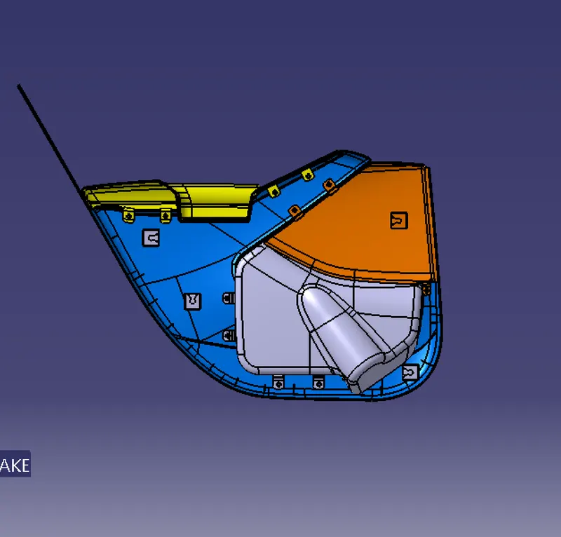
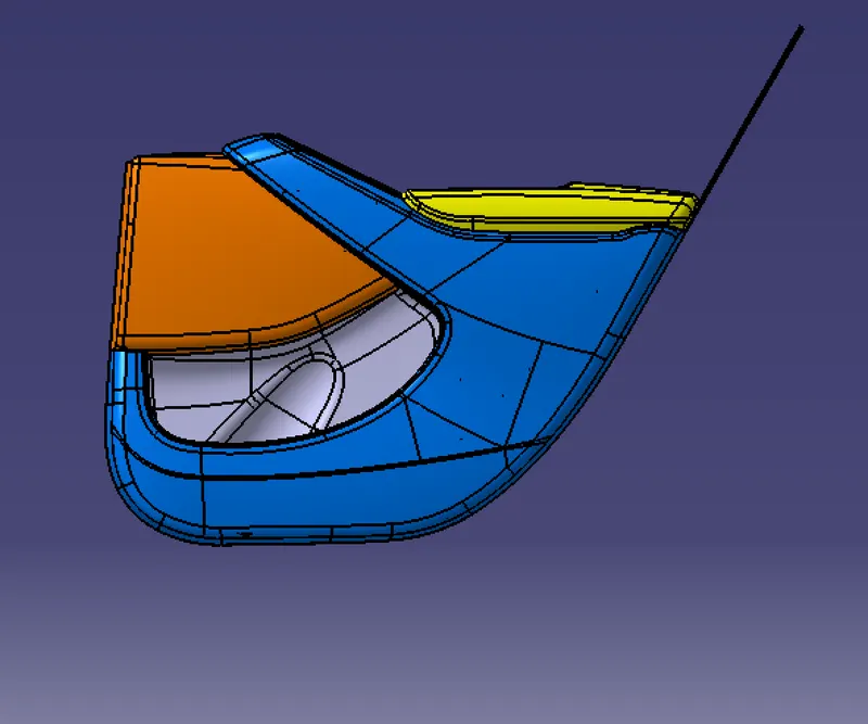
Here the image of the full model is given below.
DRAFT ANALYSIS:
The draft analysis must be performed after creating the the parts and B side features. The draft analysis can be carried out by using the main tooling axis.make sure all the faces are clearing the draft as per the requirements given by the designer.if draft are not sufficient we must inform to them and get the modified model.
The draft analysis carried out on all the parts separately and attached the images individually.
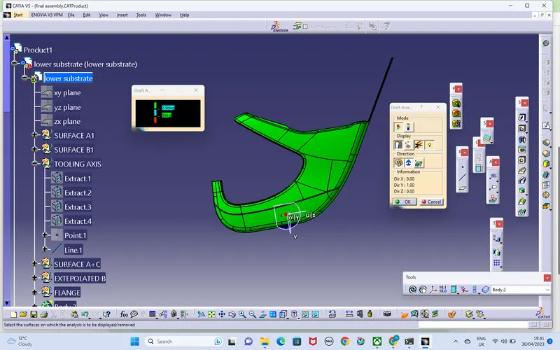
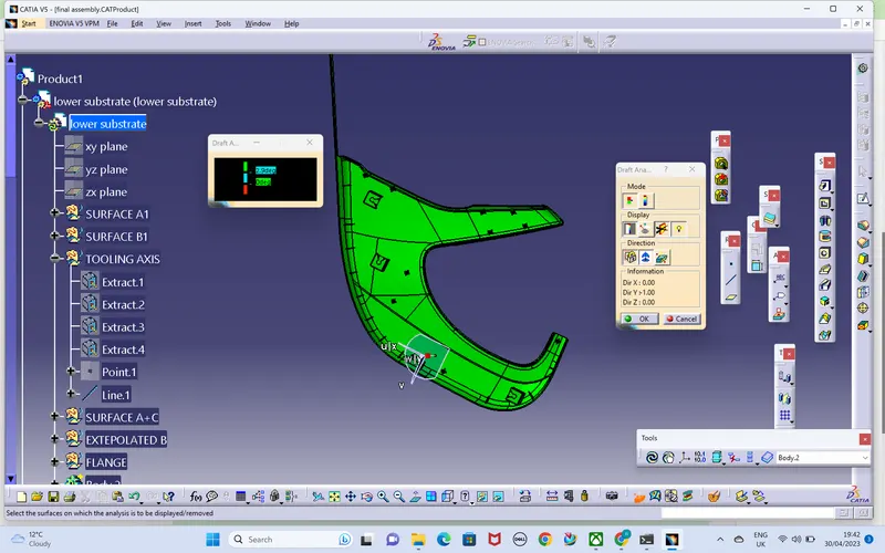
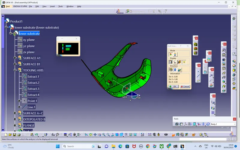
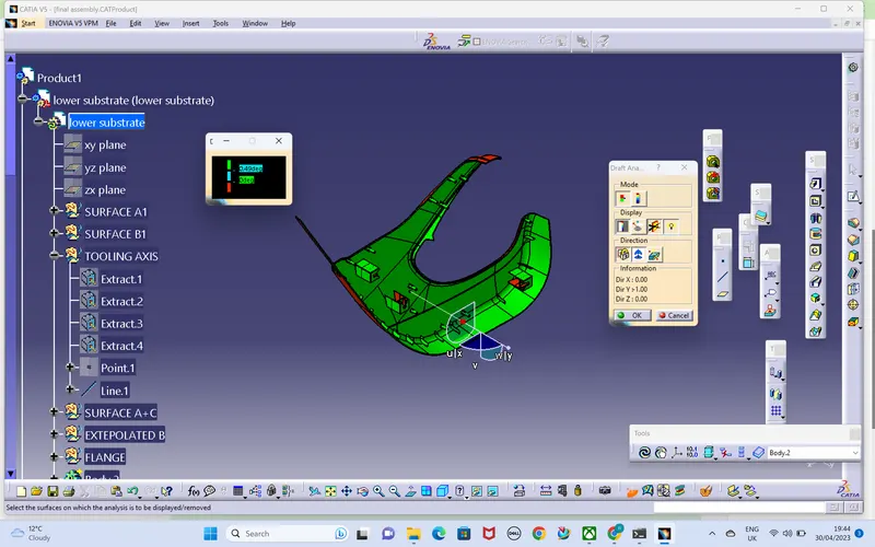
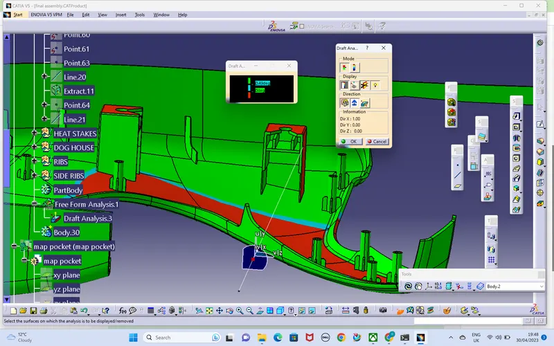
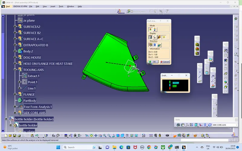
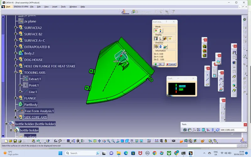
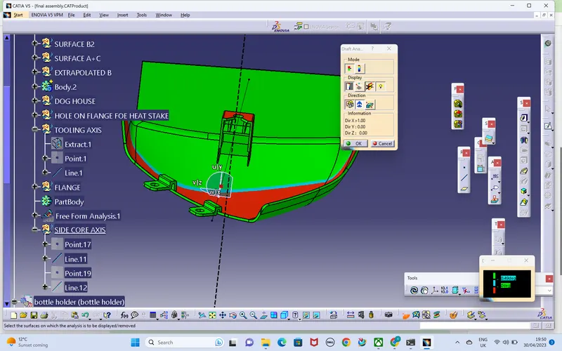
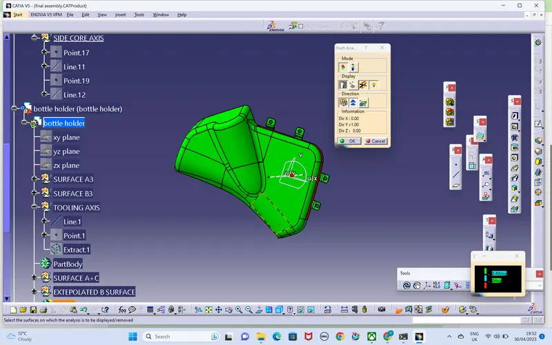
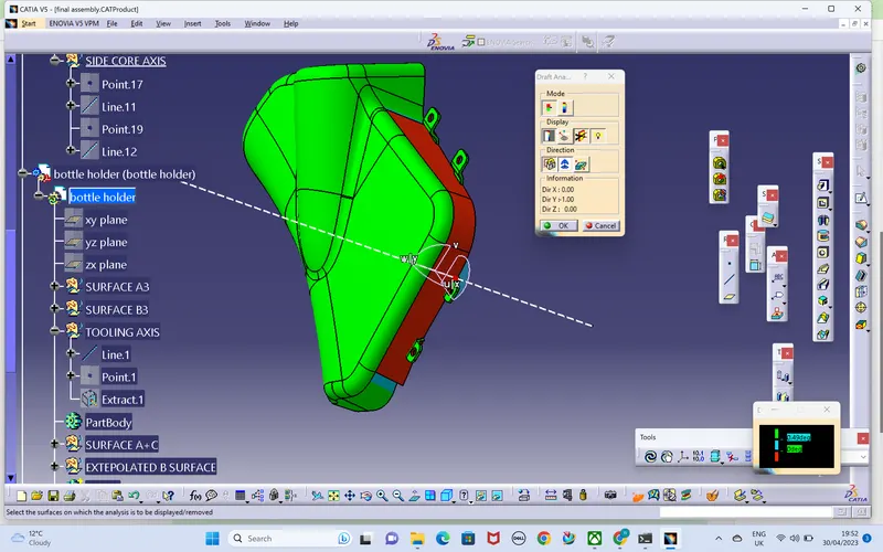
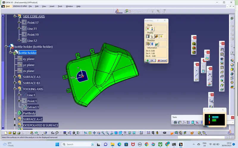
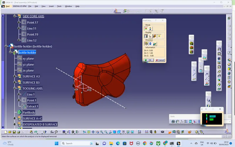
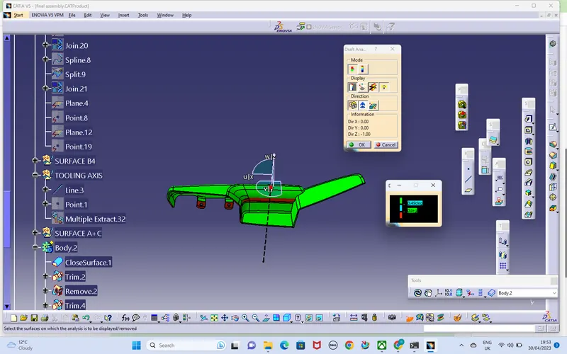
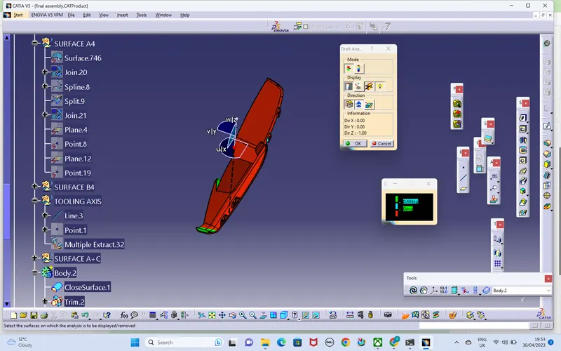
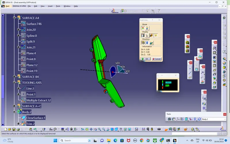
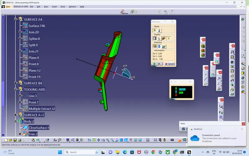
Here i have used minimum value of degree is 0.49.
PUSH PIN:
push pin is used to connect between thge sheet and the parts, push pin is placed over the dog house with coincidence command.