Week 12- Final project
DEVELOPMENT OF A DOOR TRIM PANEL
AIM:
Creation of CAD model considering following inputs as like in OEM and tier1 companies.
SPECIFICATION:
Following the Master Section given.
OBJECTIVE:
Create the DOOR TRIM component through the given class A surface. To begin with, Seperate the master section into parts and open the given surfaces seperately in a cat part.
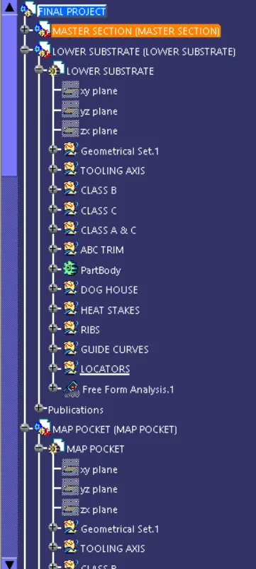
The tooling axis for the given class A surface should be created meeting the requirements of the draft angle and at the end perform the Draft analysis on the model. Create the DOG HOUSE, HEAT STAKES, LOCATORS considering the design rules mentioned.
CLASS A SURFACE:
Class A surface is an aesthetic surface with highest quality finish. Most class A surfaces for an automotive component are made using Autodesk-Alias based on the final concept-sketch.
All class A surfaces should have Curvature-continuity which means the continuity between the surfaces should share the same boundary. It is taken as a reference by the Automotive Pastic Designer to create the Class B and Class C surfaces.
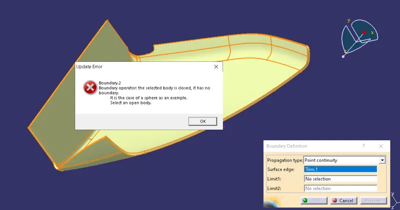
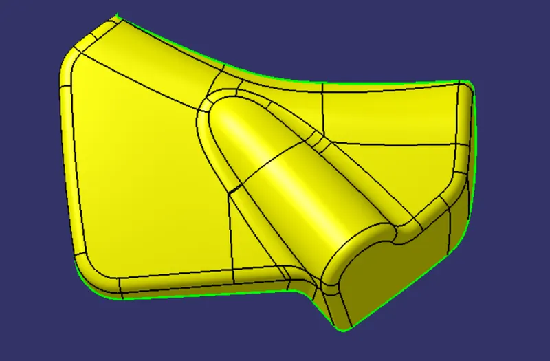
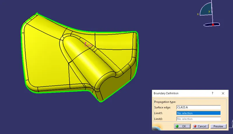
Import the given Class A surface, Check for continuity using boundary and create the tooling axis for the Class A surfaces and perform Draft Analysis.
CLASS B SURFACE:
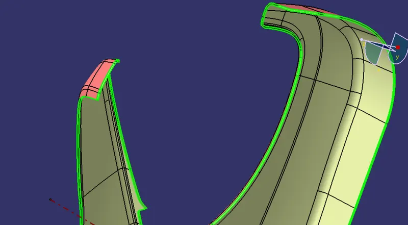
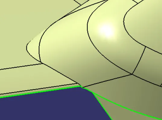
The B surface is created by OFFSETING the CLASS A SURFACE. B surface contains features like Locator, Heat stake and DOG HOUSE. Offset the class A surface for 2.5mm(Refer from Master Section). There should be some surface Dis-continuity on the offset, close the gaps.
Some Surafces may create a Error While Offseting the Class A surafce, Work on the gaps occur during offseting, Close the surface to get the complete B surface.
CLASS C SURFACE:
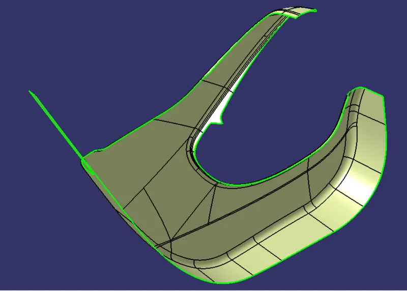
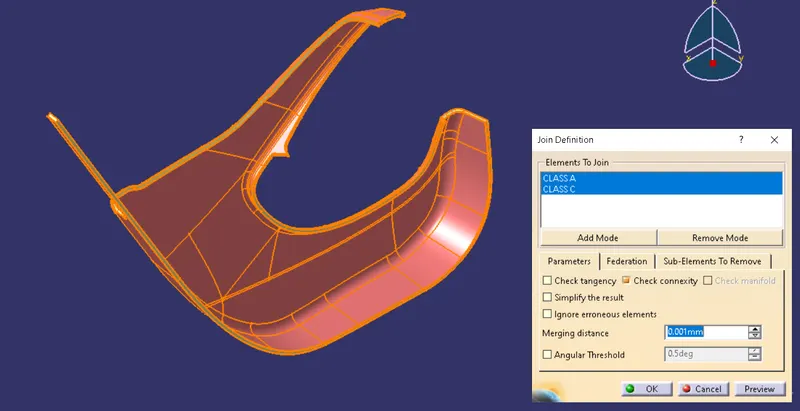
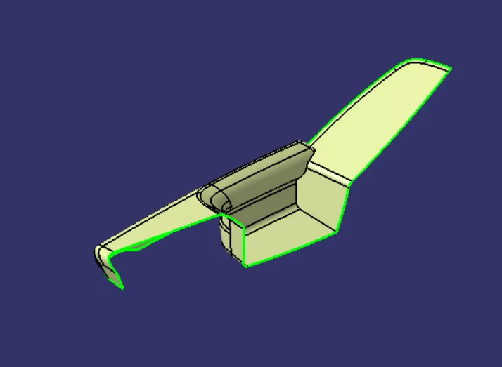
Class C surface is the surface connecting A and B surafces together. Class C surface is Created based on the edges from Class A, Class C is joined with the Class A surface and later trimed with Class B surface.
Do Sweep on the edges of the CLASS A using Reference surface and Draft Direction. I converted it into Sections and trim them together to get Class C surafce.
TOOLING AXIS:
It is the direction in which the core and cavity opens and closes. After the class A is imported check for possible irregularity, using boundary.
Extract a Surface from the Class A, create a point using on surafce option and create a line using point direction method, the created line is the tooling axis, perform draft analysis on the class A surface using tooling axis.
DRAFT ANALYSIS:
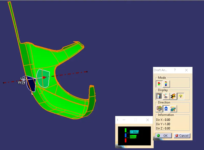
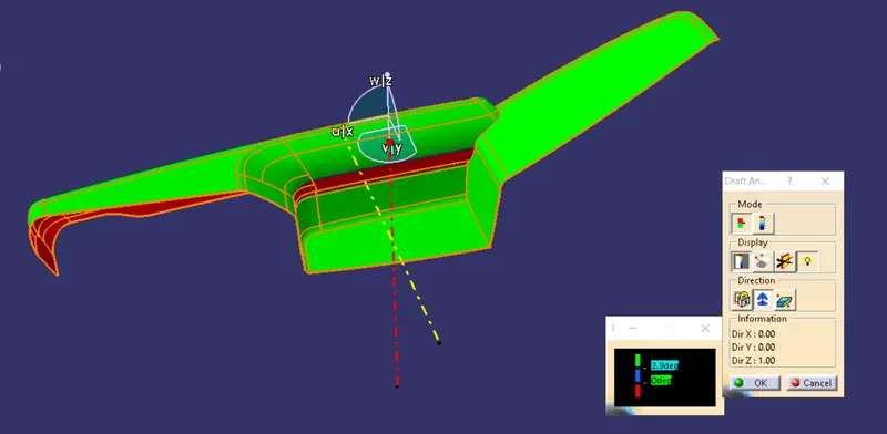
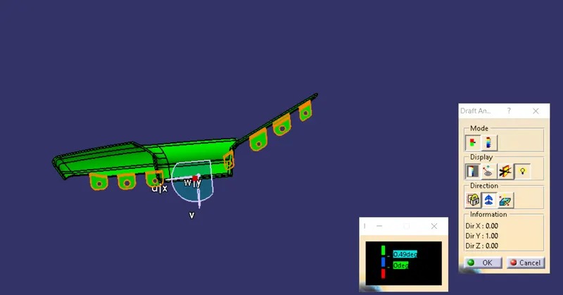
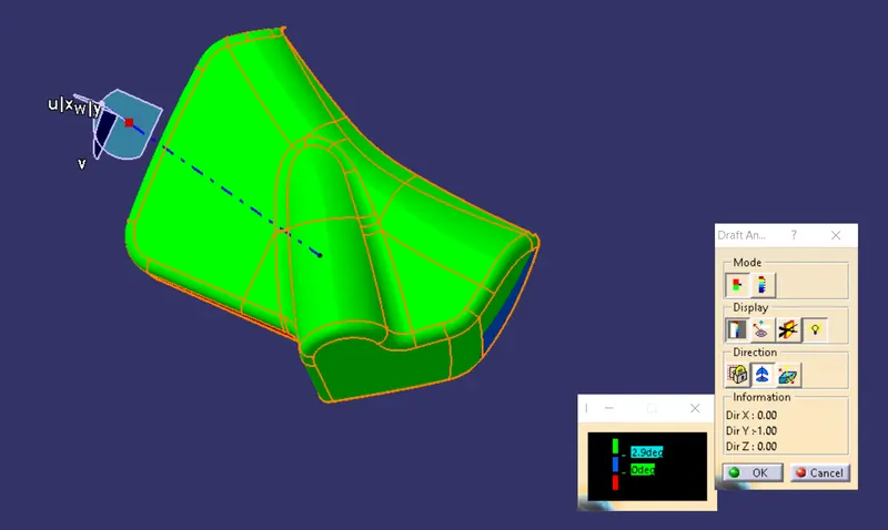
No parts can be ejected from the tool if it is having a straight 90degree profile from its base surface. A small draft angle is provide to component in order to get an easy removal from the tool. Draft analysis technique is used to analyze whether our part model created is manufacturable based on the draft condition applied.
To start the draft analysis, we will go to insert and click on the option called analysis. Select the Feature Draft Analysis, click on Quick Analysis option on mode. Under direction we will choose the icon with the symbol of compass on it. Place it on the tooling axis.
CLASS A :
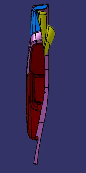
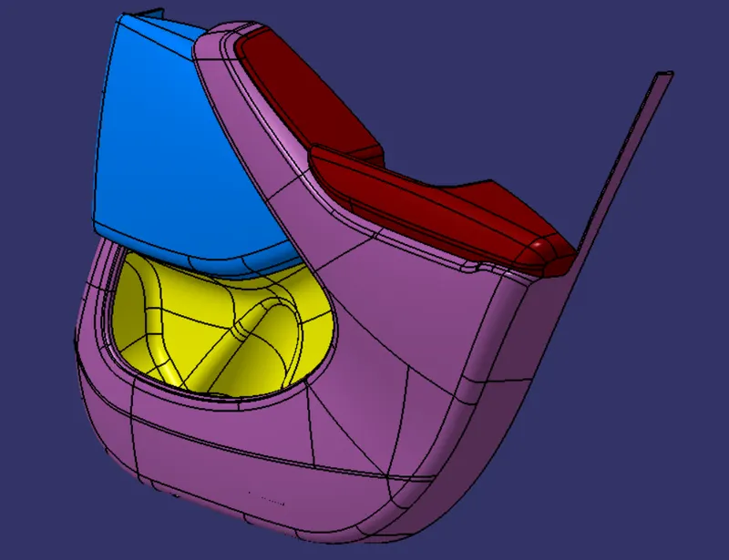
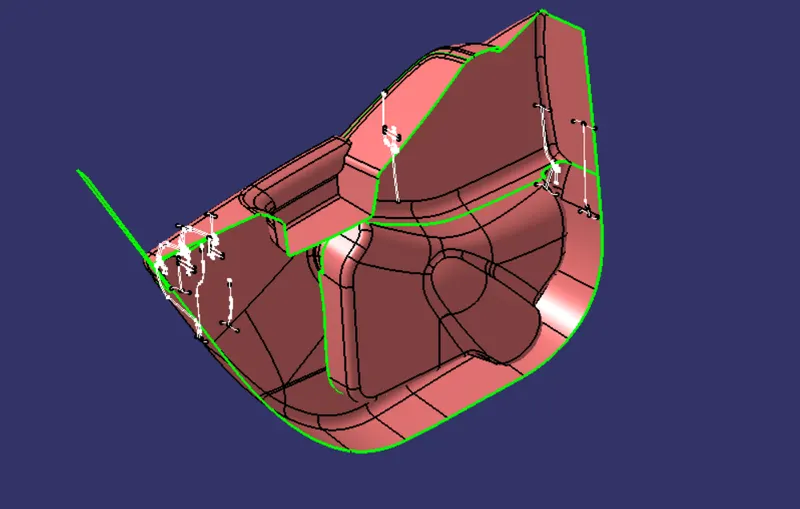
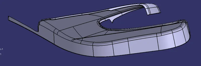
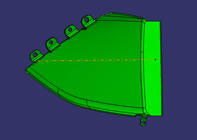
The below surface is given as Class A surafce and Master section for the Door Trim Panel.
LOWER SUBSTRATE:
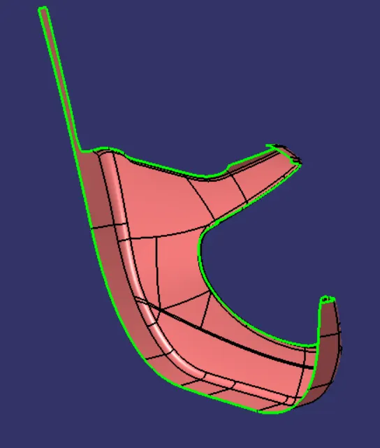
Class A of Lower Substrate seperated from the Master section.
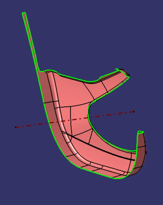
Tooling axis:
Tooling axis is created based on point direction method.
Draft Analysis:
Offset the class A surface for 2.5mm.
Class B:
Offseted Class A surafce.
Class C:
Multiple extract the Class A surface and create a boundary, Use the Boundary as profile and surface as reference to create a sweep.
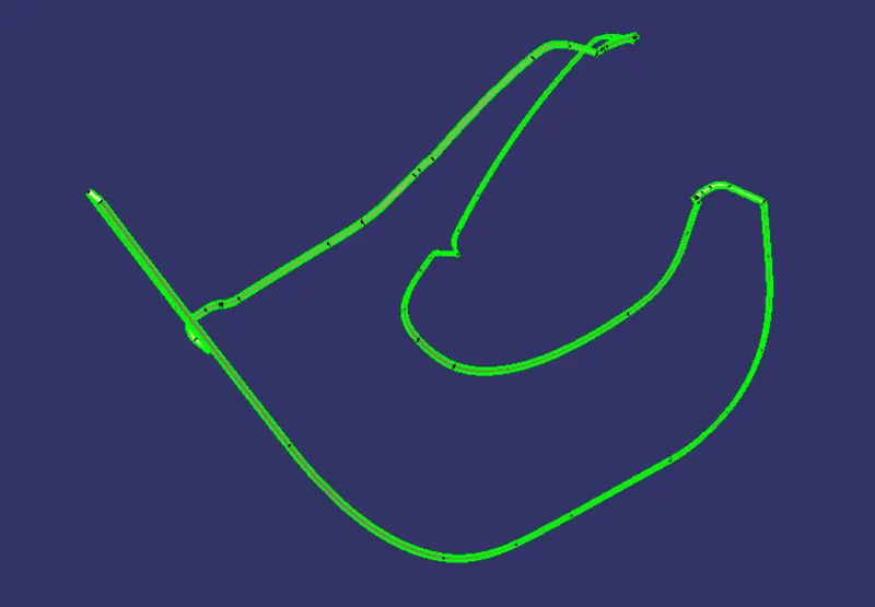
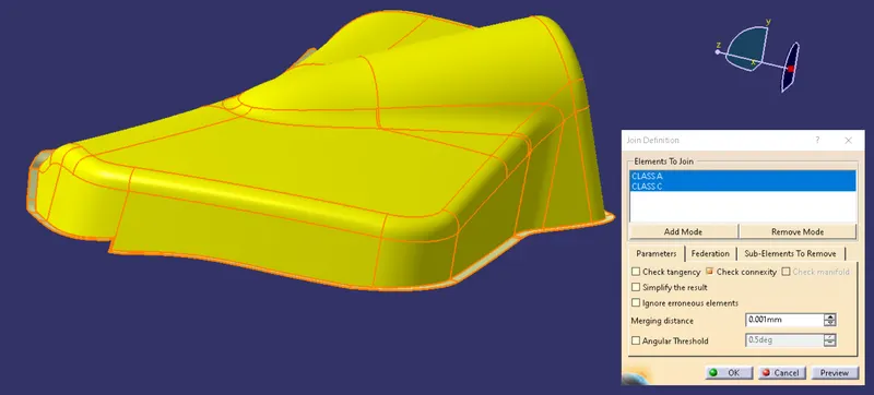
Join the Class A and C surafces together.
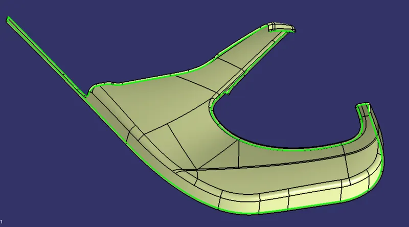
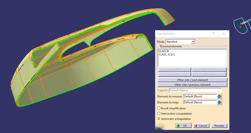
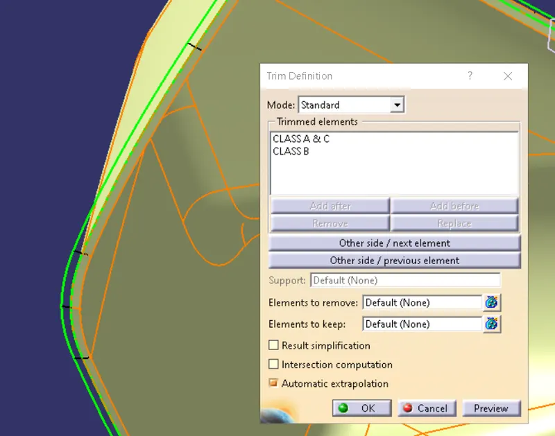
Trim the joined surface with the Class B surface.
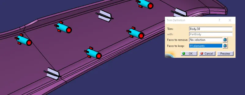
HEAT STAKES:
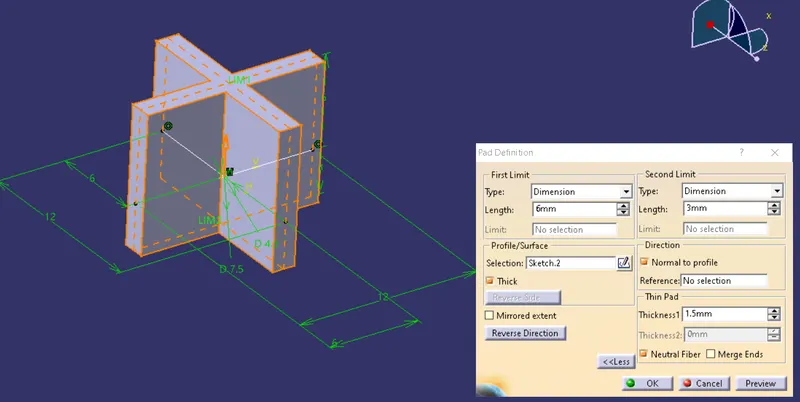
Heat staking technology is quite simple in concept. Whenever two or more components need to be attached to one another, and at least one is made of a thermoplastic, a combination of heat and pressure can be used to reform the plastic to the many shapes or profiles to retain or join the parts together,Heat stakes are created on the B side of the component.
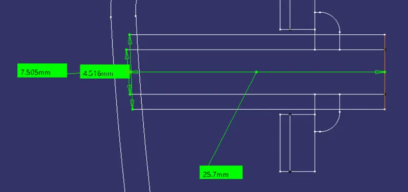
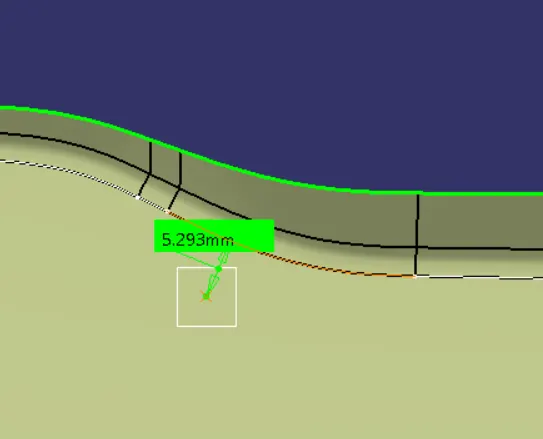
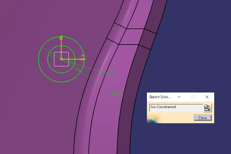
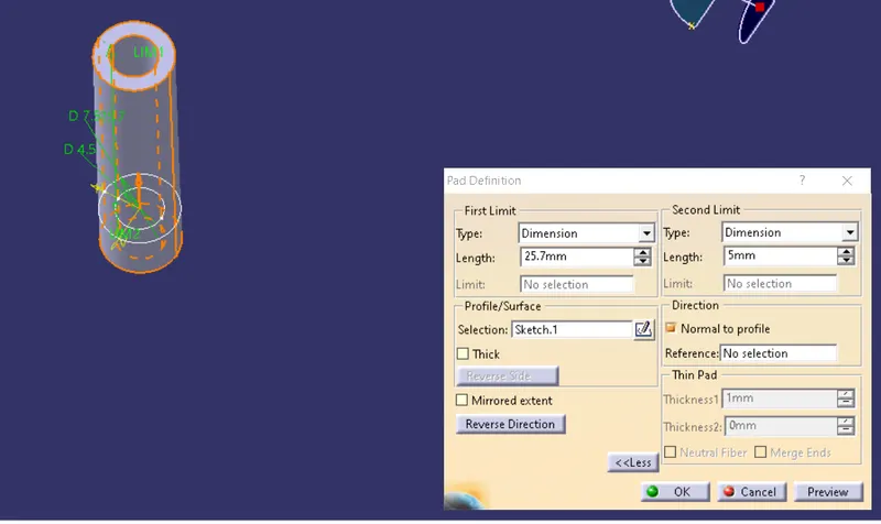
Pad the sketch as per the master section measurement.
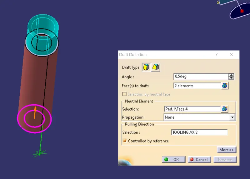
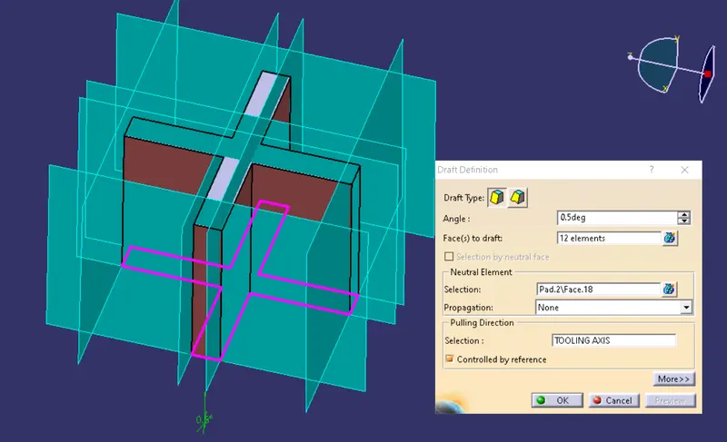
Draft the paded body.
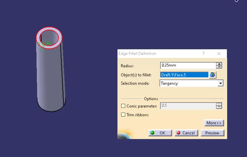
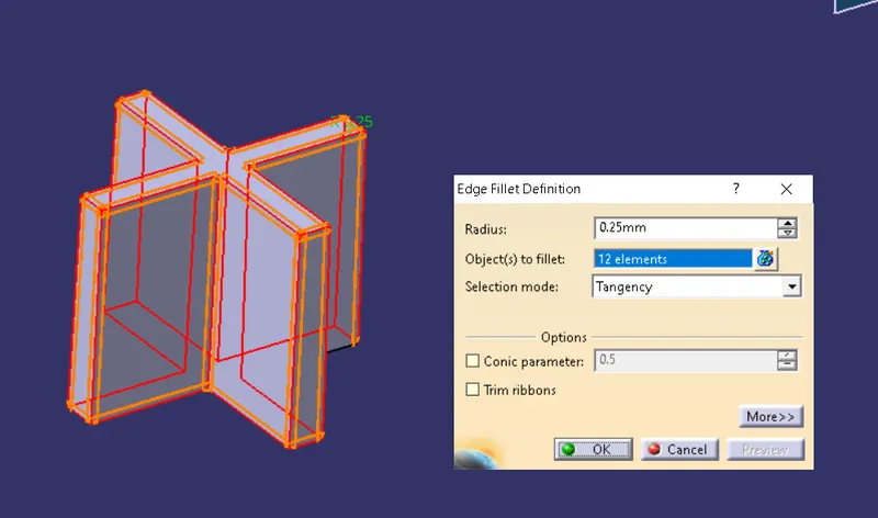
Apply fillet on the body.
RIBS:
Create ribs for the Heat stakes.
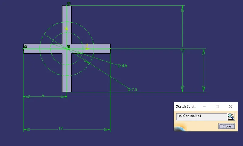
Pad the above sketch.
Draft the paded sketch.
Apply fillet on the ribs.
union trim the rib with the heat stakes.
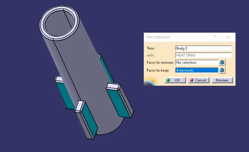
Trim the Heat stake with the Lower subtrate.
LOCATORS:
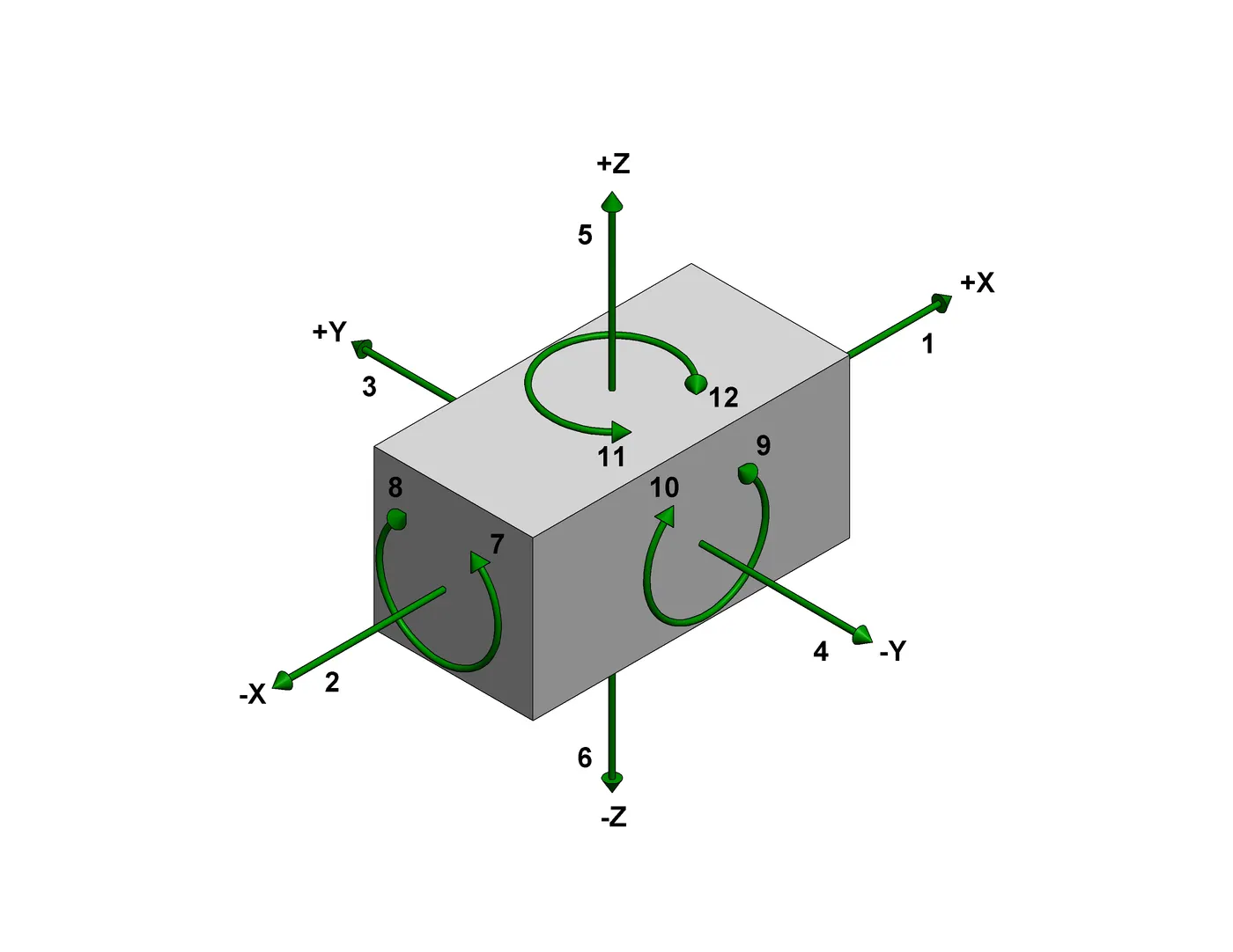
The devices that restrict a workpiece's movement are the locators. The locators therefore, must be strong enough to maintain the position of the workpiece and to resist the cutting forces.
The twelve degrees of freedom all relate to the central axes of the workpiece. Notice the six axial degrees of freedom and six radial degrees of freedom. The axial degrees of freedom permit straight-line movement in both directions along the three principal axes, shown as x, y, and z. The radial degrees of freedom permit rotational movement, in both clockwise and counterclockwise radial directions, around the same three axes.
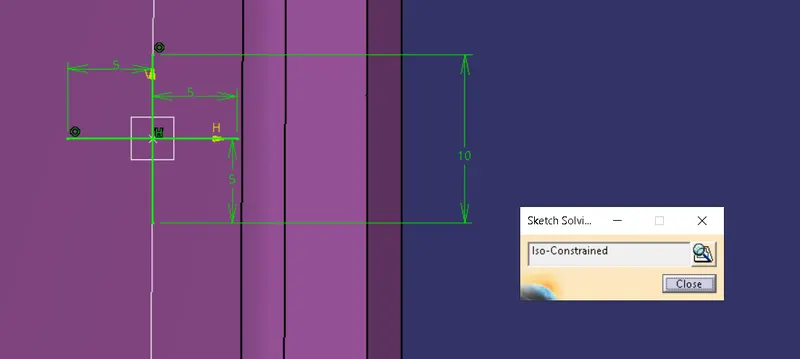
Pad the above sketch.
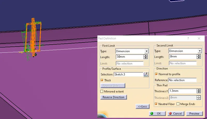
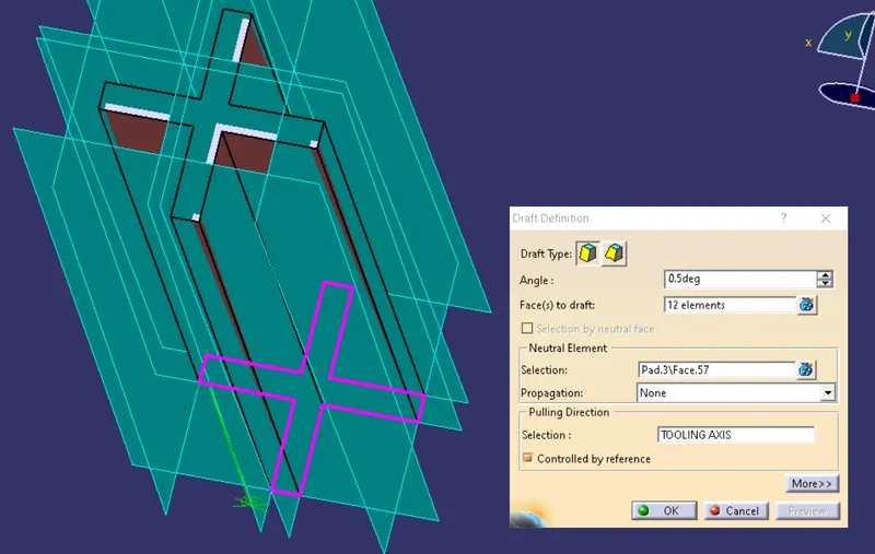
Apply draft to the body.
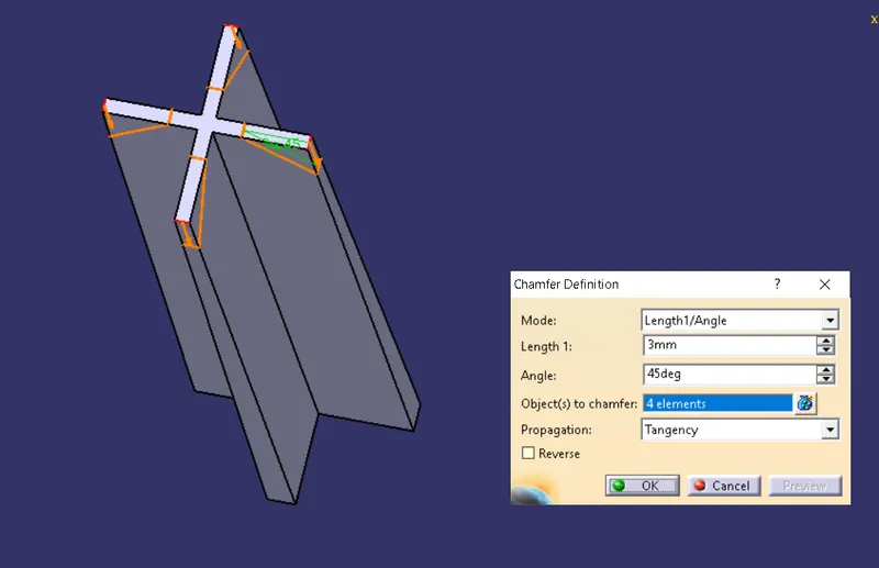
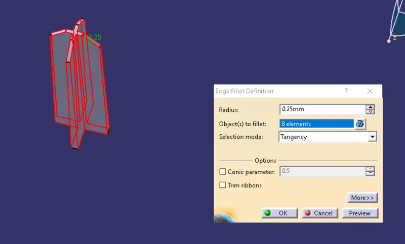
Apply fillet to the body.
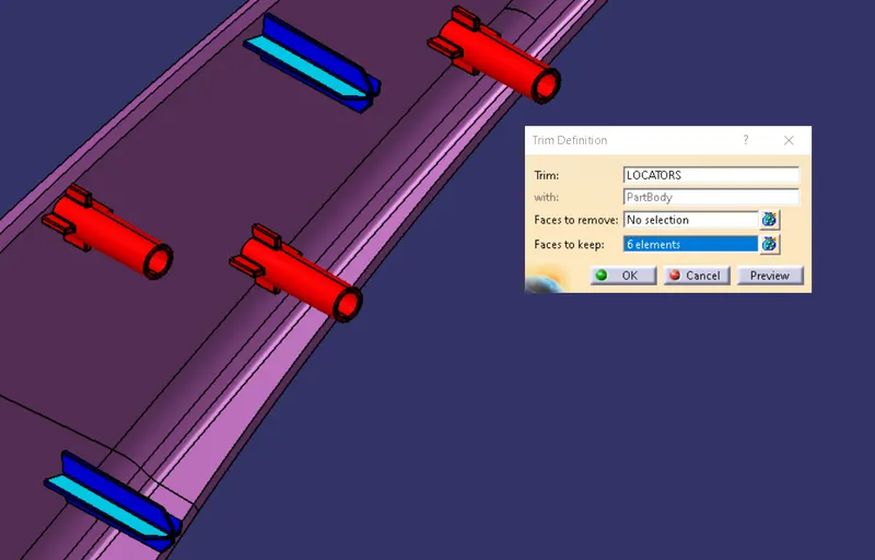
Trim the body with the Lower substrate.
DOG HOUSE:
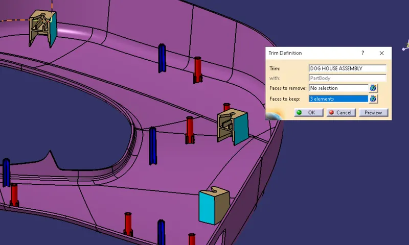
Dog house is an engineering feature used in plastic trim design. Dog houses are used as supporting feature. Sometimes other engineering features like snaps; locators etc. are mounded on them to increase their strength. Dog houses are subjected to draft analysis to prevent breakage of the component during ejection from mould cavity.
"C" is where the doghouse contacts the backside of the surface
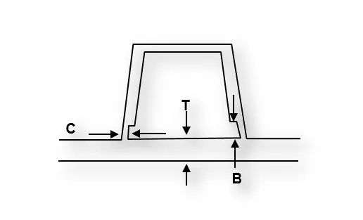
Doghouse wall thickness at the intersection of the part wall ( C ) should be 40% or less than the main wall stock ( T ).
The height of ( B ) should be between 3.0 – 6.0 mm
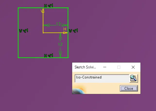
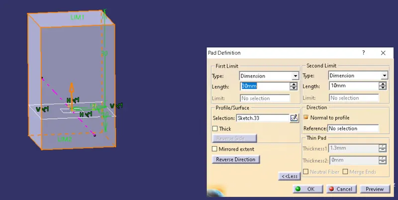
Pad the above sketch.
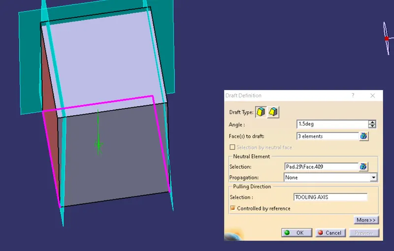
Draft the paded body.
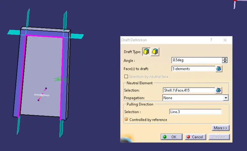
create rib for the dog house.
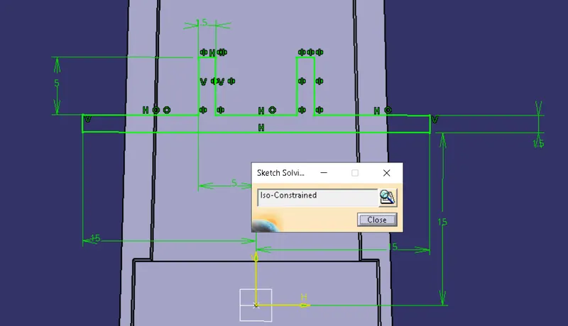
pad the rib and trim it with the dog house.
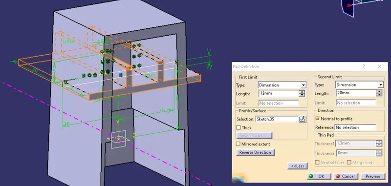
Draft analysis on the dog house.
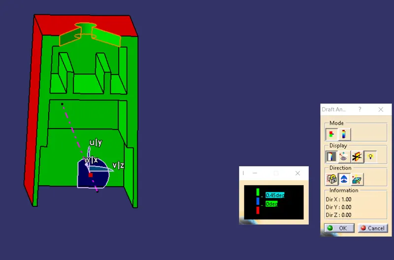
Union Trim the dog house with the lower substrate.
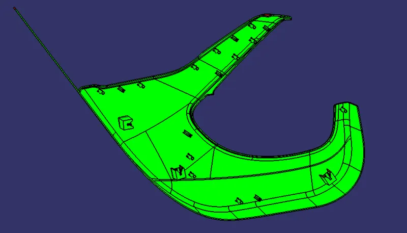
FLANGES:
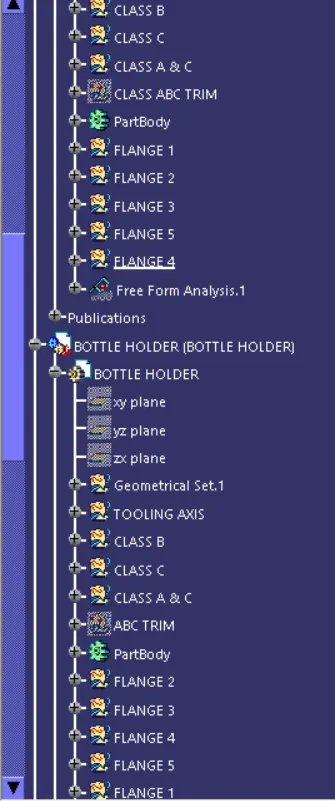
Flanges are used to connect the part bodys together.
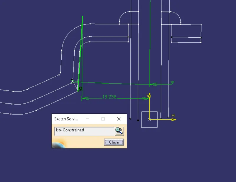
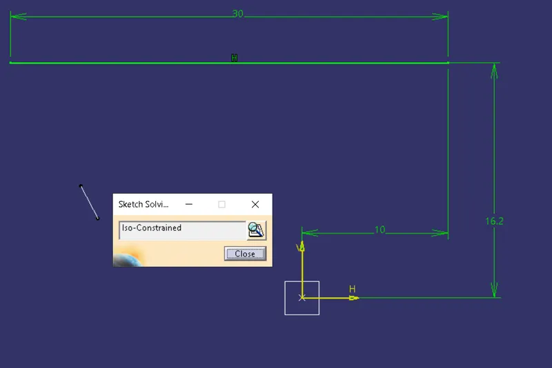
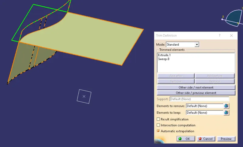
Sweep and extrude the above surfaces and trim them together, thick the trimed surface apply draft.
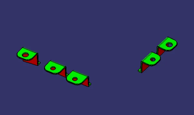
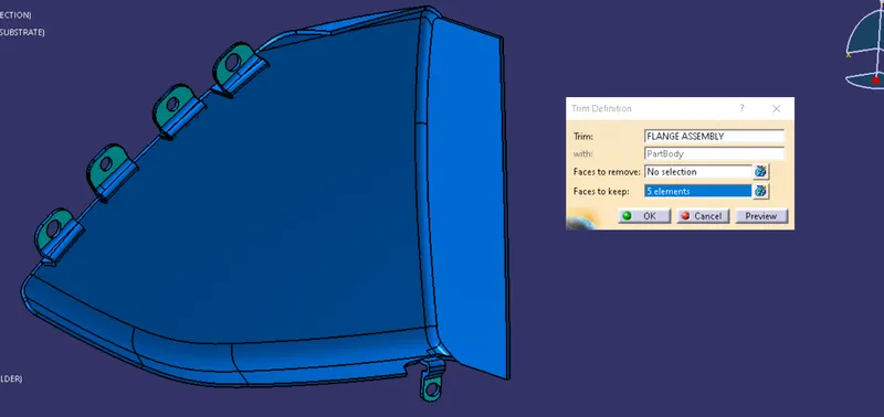
Flanges are union trimed with the partbody.
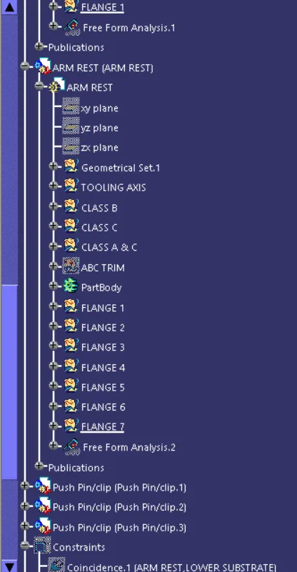
ARM REST:
Class A:
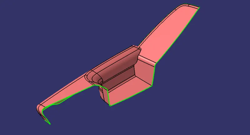
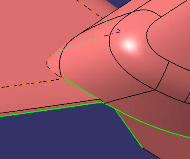
If the given surface is not proper we have to inform the class A designer about it and get approval from them.
Class B:
Class C:
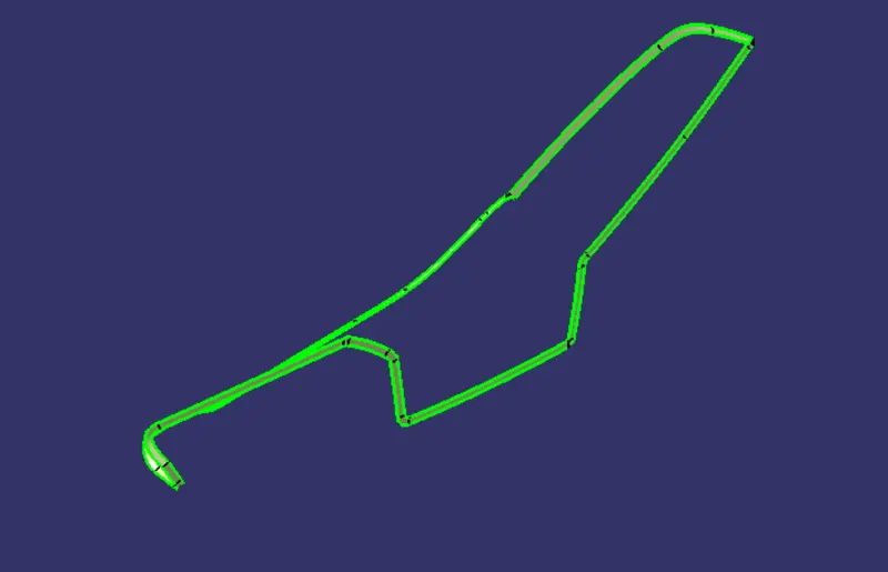
Class A and C join:
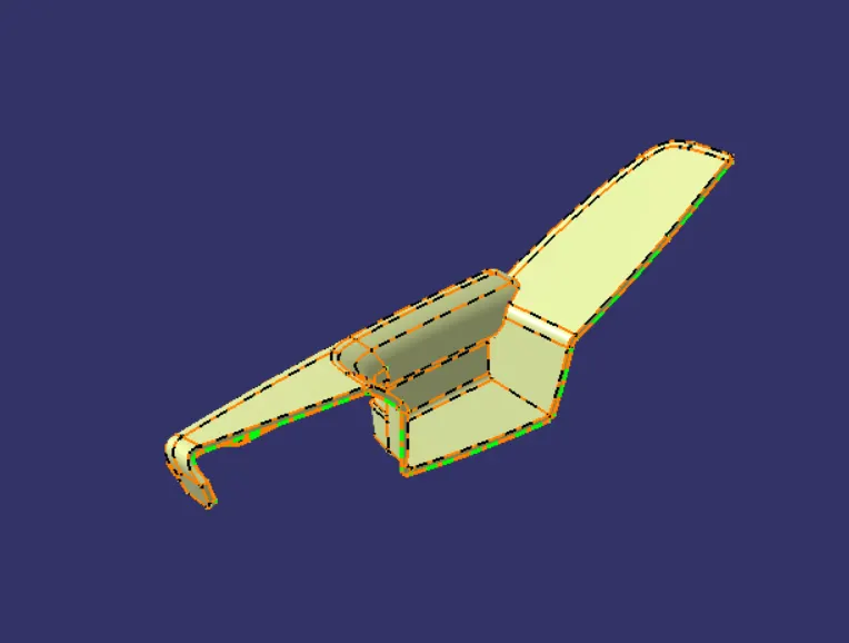
Trim the class B surface with the Above Join.
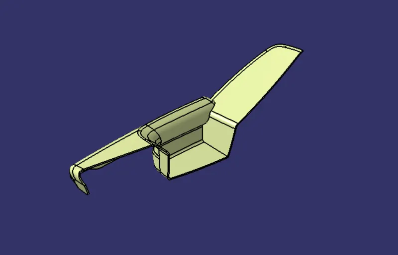
MAP POCKET:
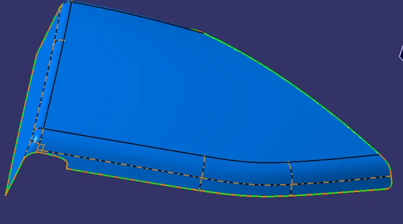
Boundary Check:
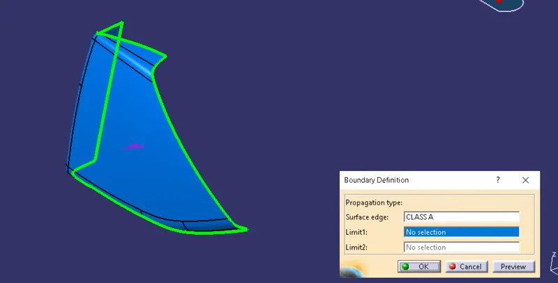
Create the tooling axis based on the point direction method.
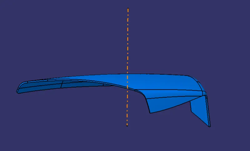
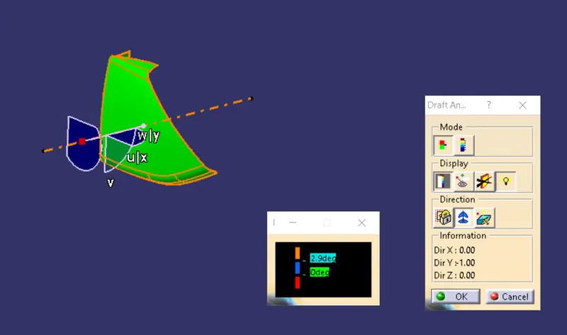
Offset the class A for 2.5mm.
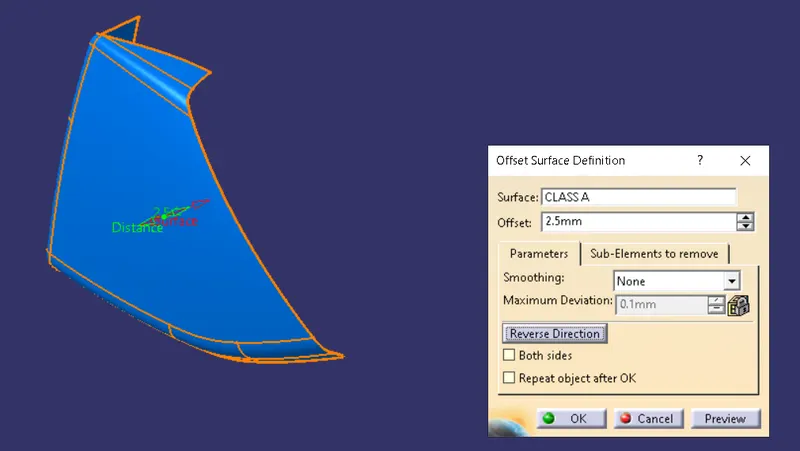
class B
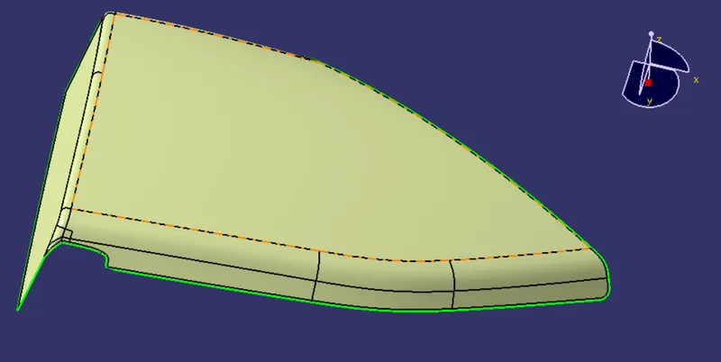
class C
class A and C join
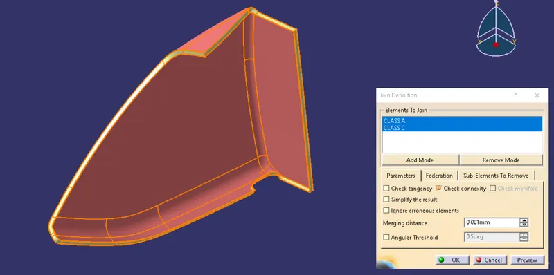
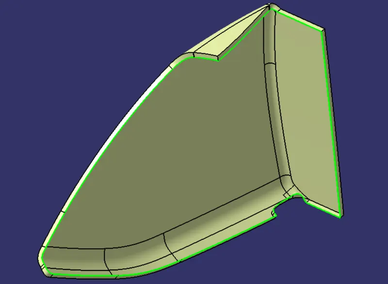
Trim the Class B surface with the above joined surface.
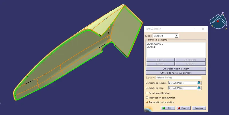
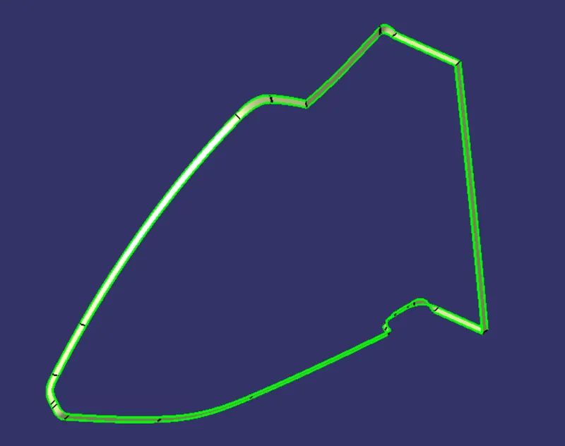
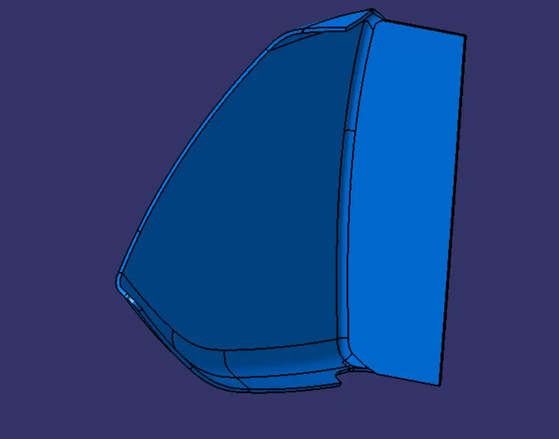
final bounadry check:
BOTTLE HOLDER:
Boundary check
class B
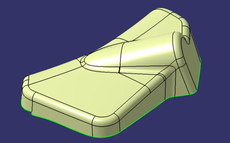
class C
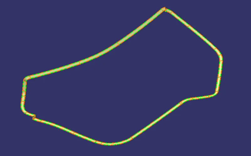
join Class A and C
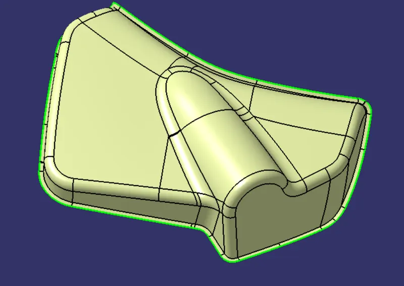
Trim the Class B surface with the above joined surface.
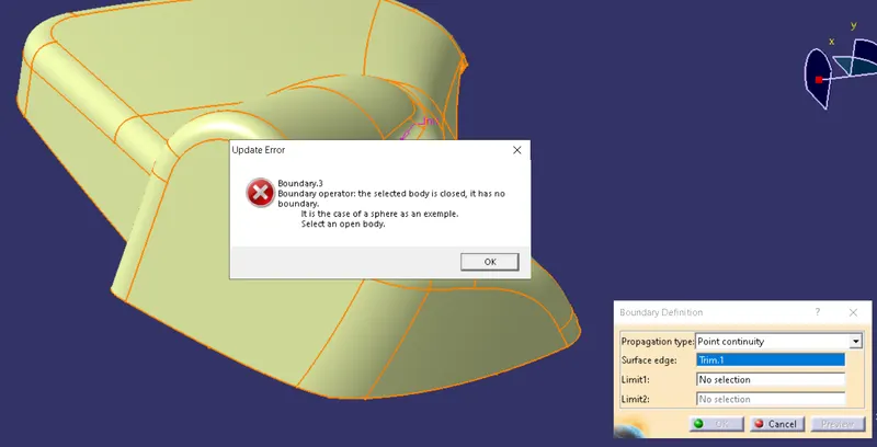
final boundary check
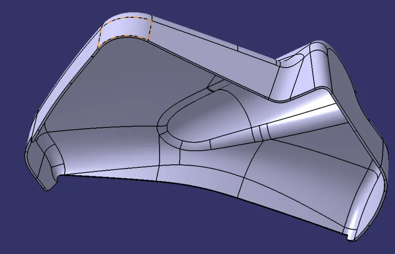
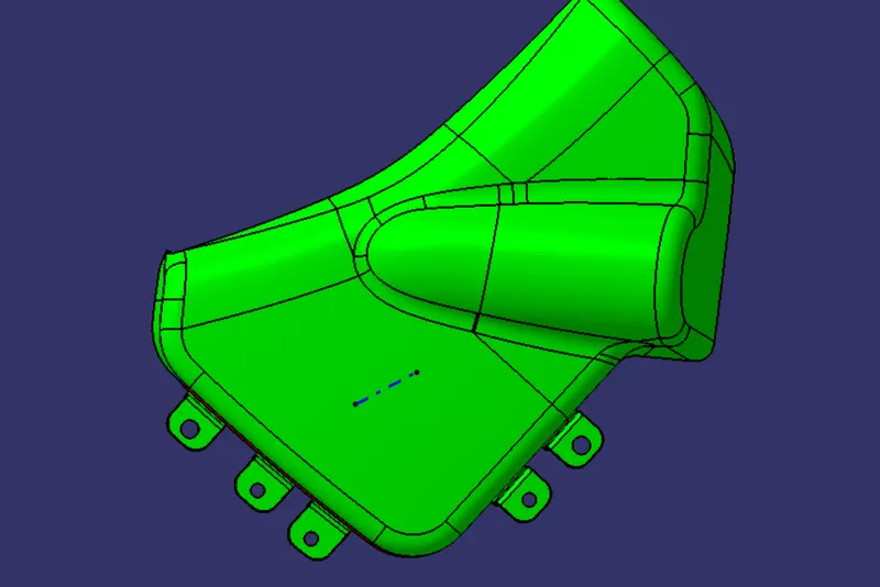
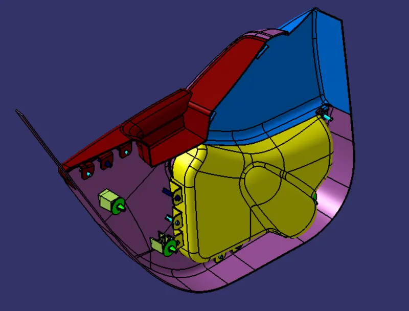
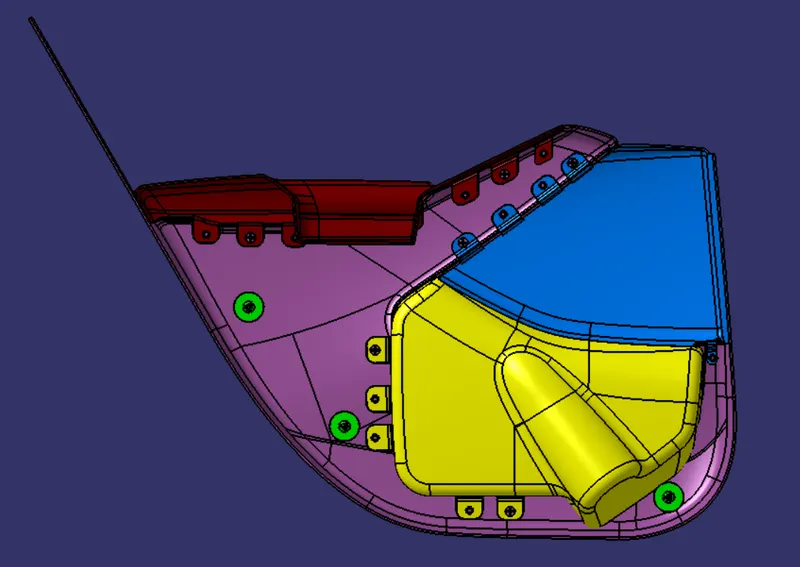
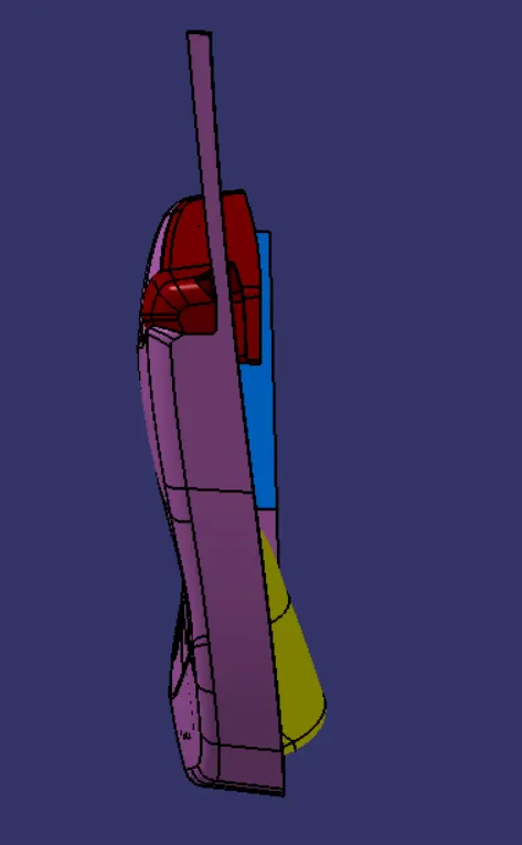
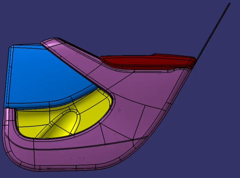
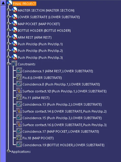
Final Assemble product: