Week 12- Final project
DEVELOPMENT OF DOOR TRIM PANEL
Aim:
To develop a solid model of Door Trim Panel from given master sections and Class A surfaces with B side features considering all the design rules and performing draft analysis.
Introducton:
Tooling Axis
- The Tooling Axis is to show in what direction does the core and cavity moves.
- It also created to give a draft angle for the final solid part.
Draft Analysis
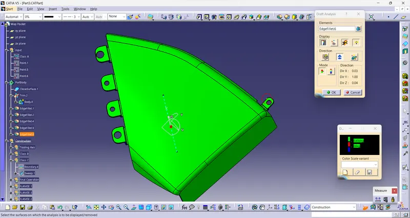
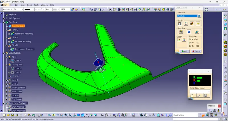
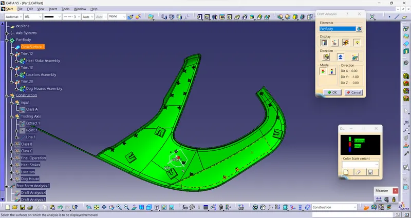
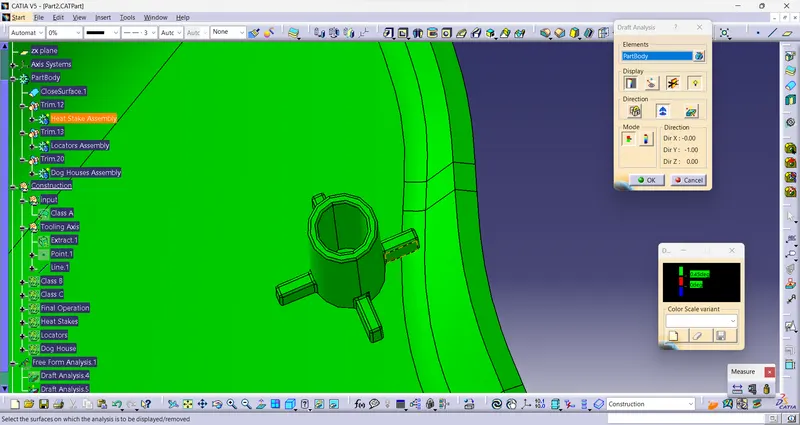
- The draft analysis is done on the basis of the Tooling Axis in order to find whether the final product is done as per the Design rules.
- The Draft angle which is assigned to the Tooling Axis defines the analysis.
- The Nominal Draft angle for the plastic product is 3 degree.
Class A
- Class A is the aesthetic surface.
- Class A is created on the basis of a concept sketch or by the predefined shape on basis of the design engineer and customer requirement.
- Class A is given to the Product design engineer in order to get the final solid part.
Class B
- Class B is the surface that is created by the product design engineer in order to get the final product from the class A surface.
- Class B is created based on the thickness that the final solid part should be.
- In other words, Class B is an Extended version of Class A with some thickness gap between them.
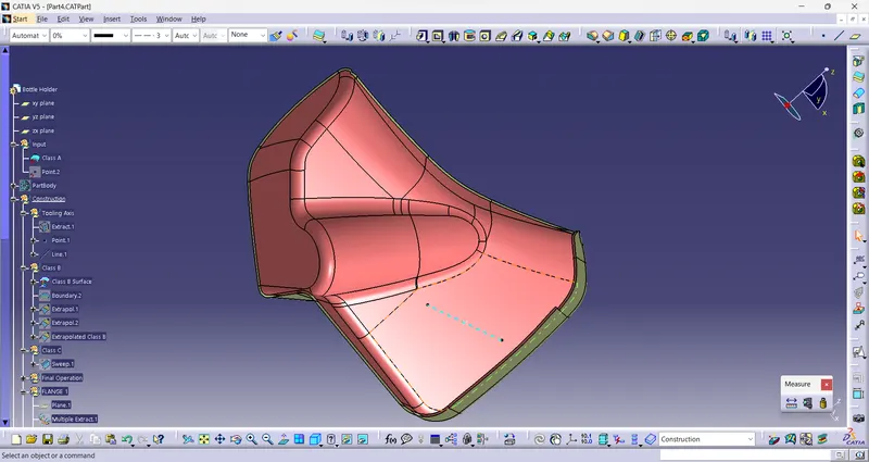
Class C
- Class C is the surface that is designed by the product design Engineer.
- Class C is created inbewteen Class A and Class B in order to connect them.
Master Sections
- Master sections are the sectional view of model which is guiding section fro designer to create solid component. Aster section provides nominal thickness of part, B side feature dimensions and location of features.
Heat Stakes
- Heat stakes are used to joint two components by melting the over the other component which fixes the components together. The process is called as Heat Staking. This reduces machinery cost because the machinery get more simple. Using this technique, we can use multiple fasting points. The weld is more dense compared to altenative methods.
Locators
- Every component has 12 degrees of freedom id 3D space.
- Locators are used to restrict this DoF. There are 2 types of locators:
- a. 2 Way Locator
- b. 4 Way Locator
Dog House
-
It is an engineering feature created on B surface of component. It is used as supporting feature. Other engineering features like screw boss, locatore are placed above dog house to increase the height.
It also helps to create fetures perpendicular to the tooling axes, and helps to avoid sink marks.
Procedure:
Studying the Input
To start the project Master sections are provided. Firstly will go through the sections ans surfaces to get an isde about the door trim.
Given Class A surface and Master Section:
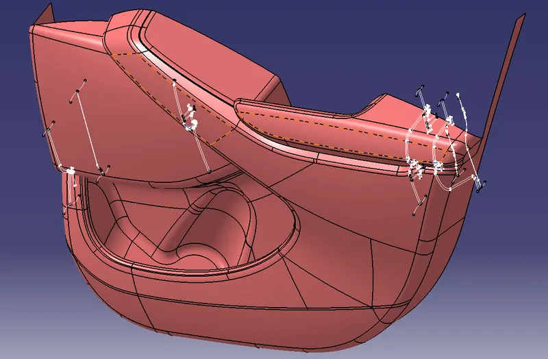
in this project, there are 4 major parts of Door Trim and need to create solid models of alll the components to complete the door trim.
- Arm Rest
- Map Pocket
- Lower Substrate
- Bottle Holder
Procedure:
Creation of Tooling Axis:
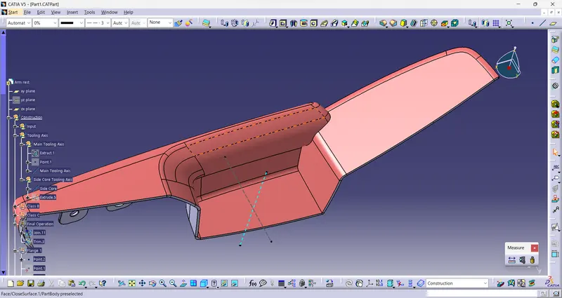
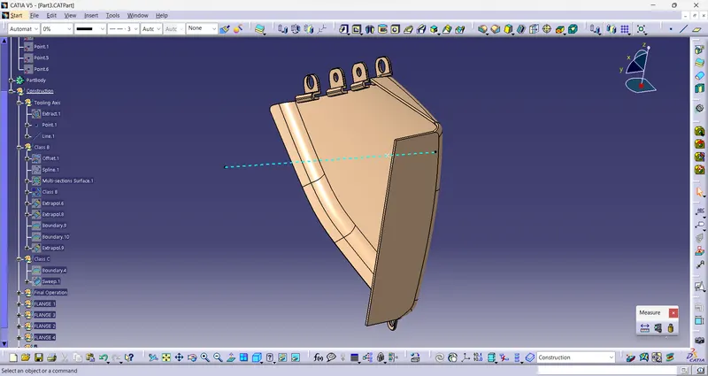
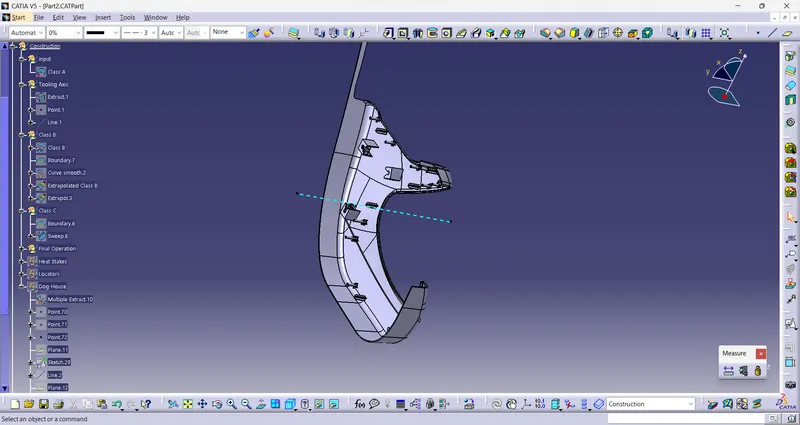
Tooling axis is created using bisecting method and by taking the reference of the master sections for both side core axis and main tooling axis.
- Arm Rest
- Map Pocket
- Lower Substrate
- Bottle Holder
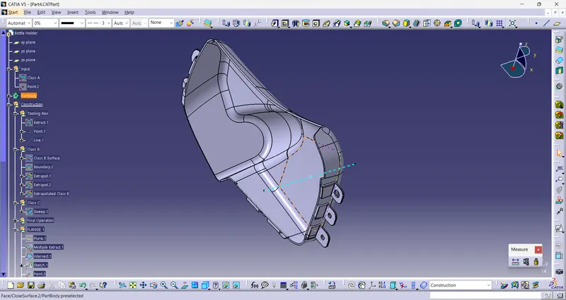
Class B Surfaces
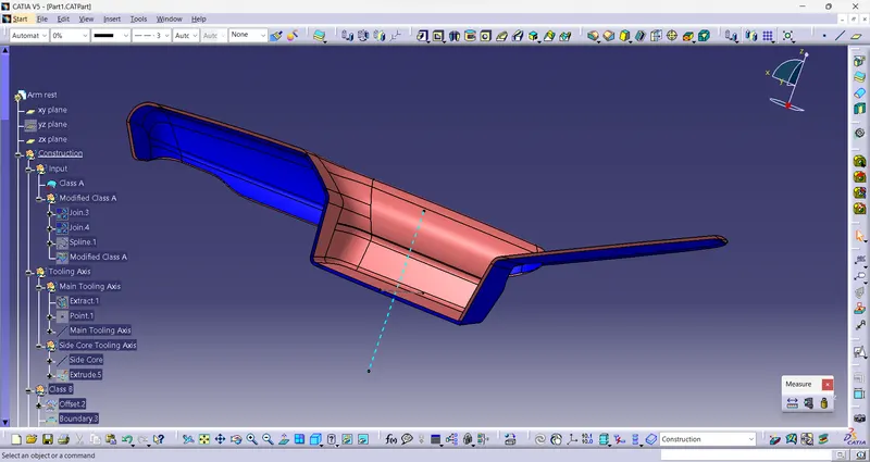
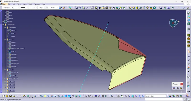
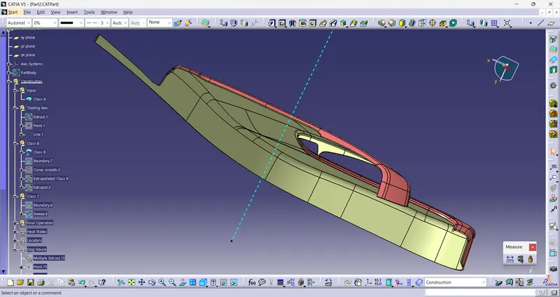
To create the Class B surface, the class A surface is offsetted at a distance of 2.5 mm(Nominal thickenss as per MAster section). Due to this, some area was unable to offset. This surfaces were recreated using extrapolate, multi section solid and spline command.
- Arm Rest
- Map Pocket
- Lower Substrate
- Bottle Holder
Class C
- Arm Rest
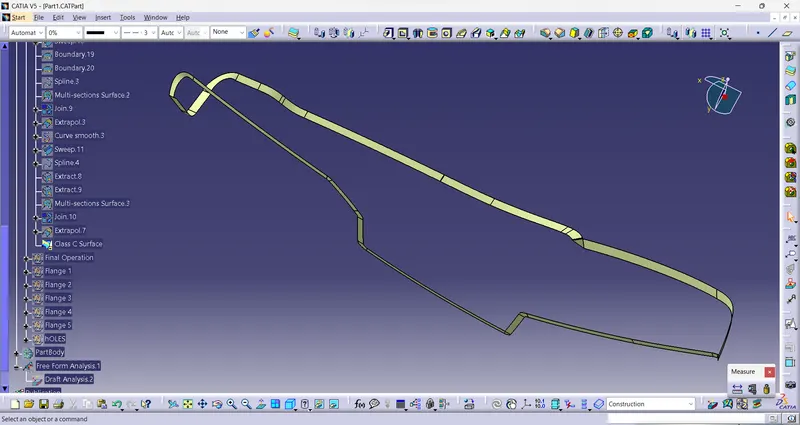
- Map Pocket
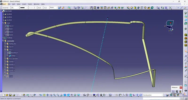
- Lower Substrate
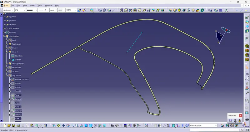
- Bottle Holder
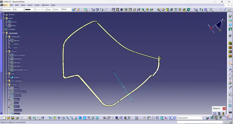
Solid Model
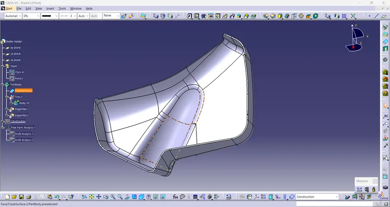
After creating Class B And Class C surfaces, Class C surface is joined with class A surface and then the output is trimmed with the Extrapolated Clas B surface. With this , a closed volume is created. Used boundary option to check whether it is completely closed or not, if not then a boundary is created.
- Arm Rest
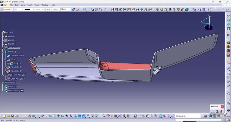
- Map Pocket
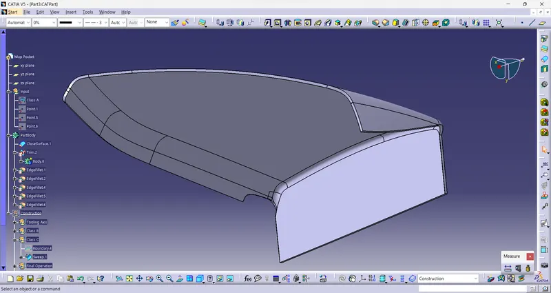
- Lower Substrate
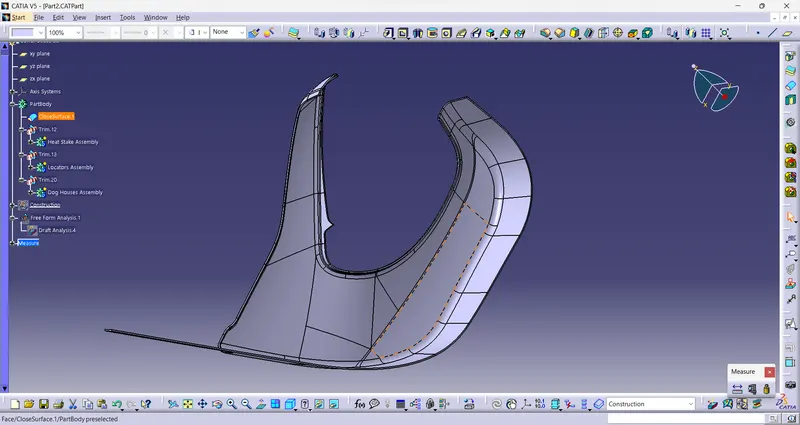
- Bottle Holder
Engineering Features
A. Heat Stake
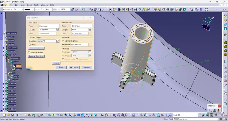
To create a Heat Stake, firstly checked the master section for Heat stake. A point is created in between the bottom points of master section of heat stake. The point is isolated and desined by using coordinates. A plane is cretaed at the point perpendicular to the tooling axis.
the outer and inner diameter is measured from master section and a positioned sketch is drawn at the point. Solid is created using Pad command. A draft of 0.5 degree is provided to inner and outer surace of the heat stake.similarly, Ribs are created to support the heat stake with 0.5 degree draft. The ribs are trimmed with heat stake using boolean operation. to create heat stake at multiple positions Translate command is used.
All the engineering features were created on Lower substrate as it is the fix part of Door Trim and all the other parts will attached to this.
Heat Stake with Ribs:
B. Locators
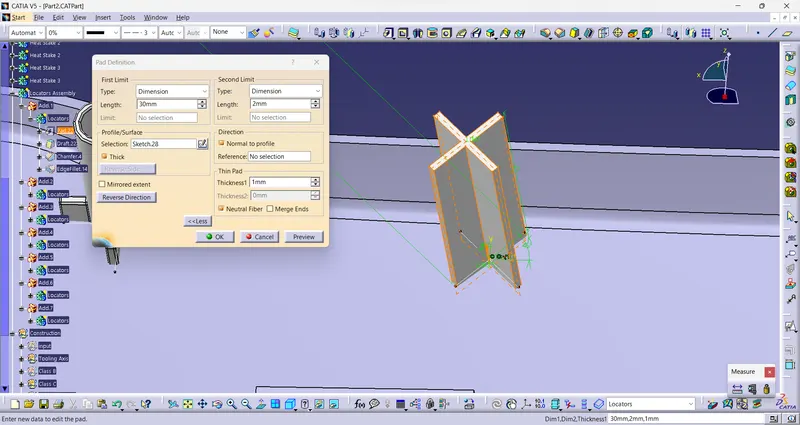
Creation of locator is same as the rib for heat stake. Only the height of locator is more than the haet stakes. A draft of 0.5 degree and fillet of 0.25 mm is also provided.
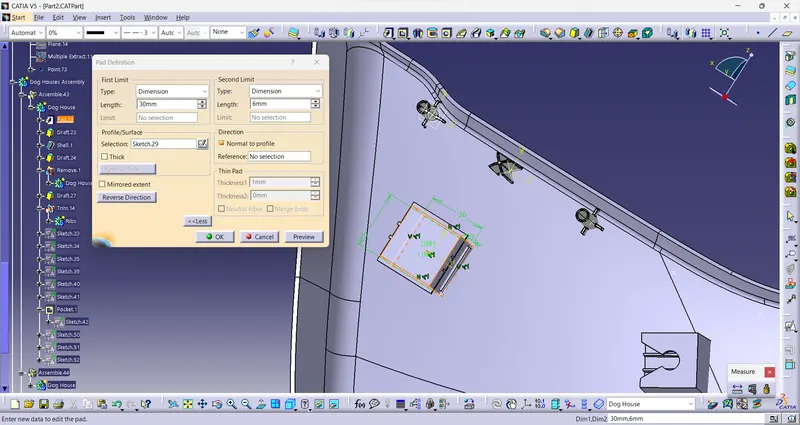
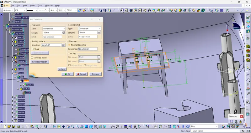
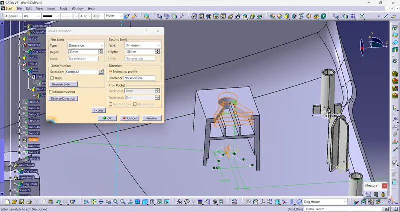
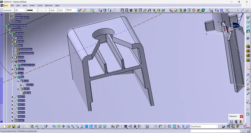
C. Dog House
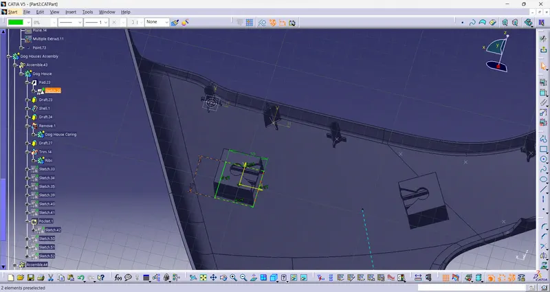
As per the master section, Dog house is created to support Push Pin Clips for assembling Door Trim in BIW.
The thicknes of dog house wall is same as 2.5 mm. A draft of 1.5 degree is provided to outer walls and dfaft of 0.5 degree is provides to the ribs as inner surfaces.
D. Flanges
Flanges are created using class C surface of part every part. And holes of required diameter are created in the flanges.
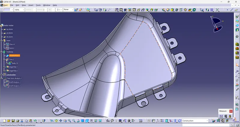
Draft Analysis of solid parts with Engineering Features:
- Arm Rest
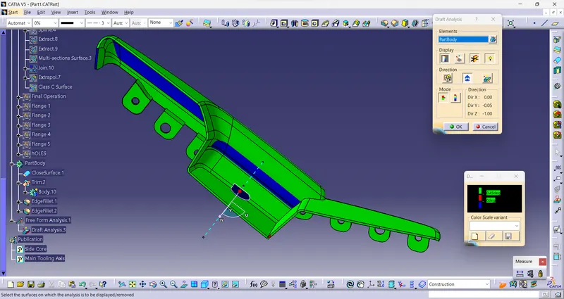
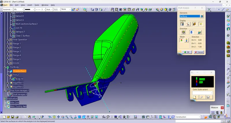
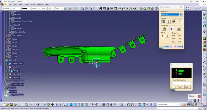
- Map Pocket
- Lower Substrate
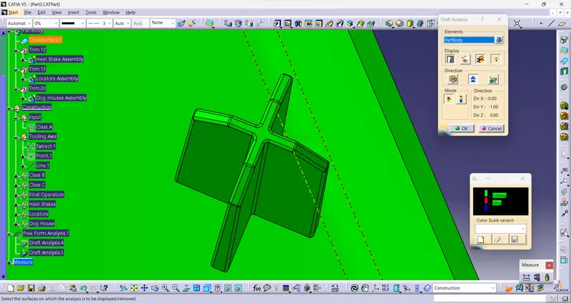
- Bottle Holder
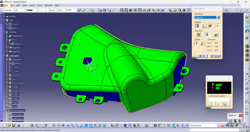
Final Model:
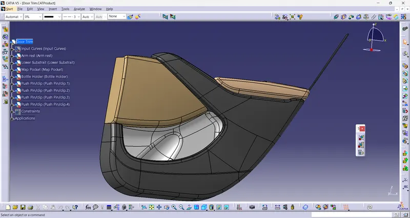
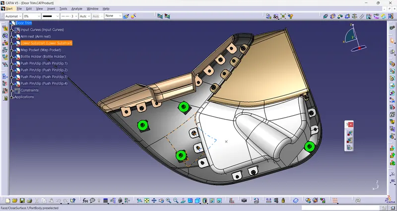
Conclusion:
Successfully crreated Door Trim assembly from given master section and Class A Surface along with B sidde features like Heat Stake, Locators and Dog House with push Pin Clips.