Week 12- Final project
AIM
To Create CAD model of a Door Trim panel considering inputs as like in OEM and tier1 companies
THEORY
Tooling Axis
Tooling Axis is the direction in which the mold or core and cavity opens and closes. While designing a component first thing is to define the tooling axis.
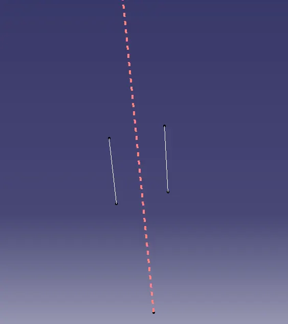
By Bisecting Method
- Check the connectivity of given Class A Surface i.e no gaps between the surfaces.
- Analyse the component along x,y,z direction and check which is the best possible tooling direction.
- Create a point at base surface by extracting it.
- Create an axis system with that point as origin.
- Create an intersection of class A with axis system.
- Create two lines with reference of faces which we think will create problems.
- Create a bisecting line with the lines drawn, which will gives us the tooling axis.
By point & Direction
- Check the connectivity of given Class A Surface i.e no gaps between the surfaces.
- Analyse the component along x,y,z direction and check which is the best possible tooling direction.
- Create a point at flat surface by extracting it.
- Draw a line perpendicular to extracted flat surface through the point and that is the tooling axis.
Draft Analysis
Draft analysis is used to analyze whether the part model created in CAD id manufacturable based on the draft condition applied.
Draft is required on all parts in the direction of mold movement in order to allow parts to release or eject from the mold properly. Most part or application require minimum `0.5^o - 1^o` as draft angle, however `3^o` is widely accepted as the norm.
Procedure
- First change the view to " Customize View Parameters" and select Material option.
- Select Feature Draft Analysis from the tool bar.
- Click on the direction, drag and drop the compass to the component such that it should coincide with the tooling axis.
- Lock the draft direction and click on the component.
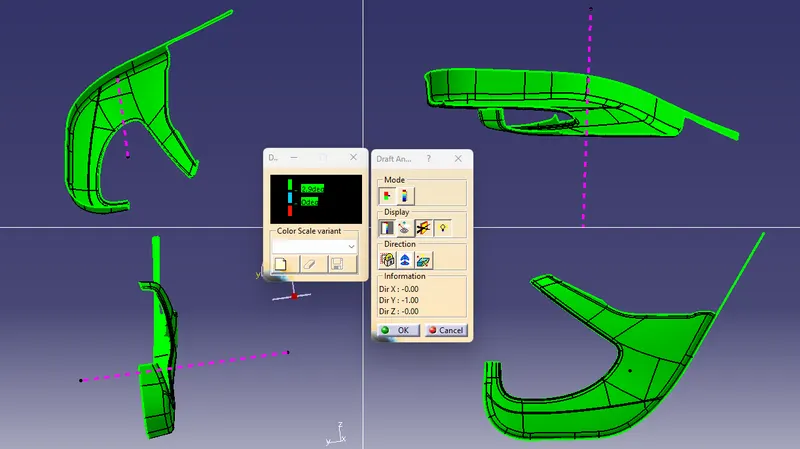
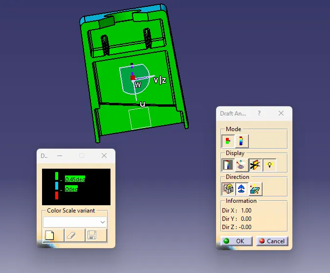
- Green colour shows the positive draft, cyan as zero degree and red as negative draft
Heat Staking
In manufacturing products with thermoplastic components, it is often necessary to join a thermoplastic to apart of dissimilar material, whether it be a metal, dissimilar plastic or other material. This technical information sheet provides design guidelines, configurations and techniques for successful heat staking.
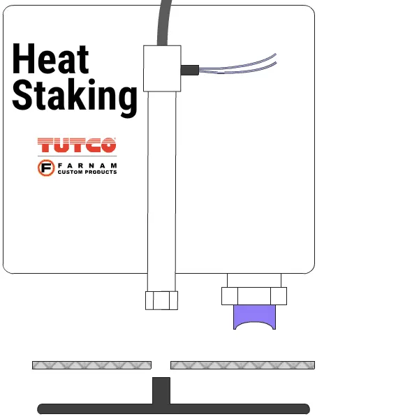
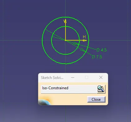
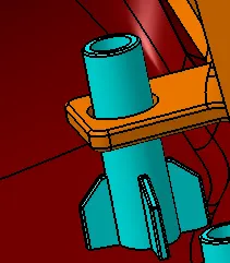
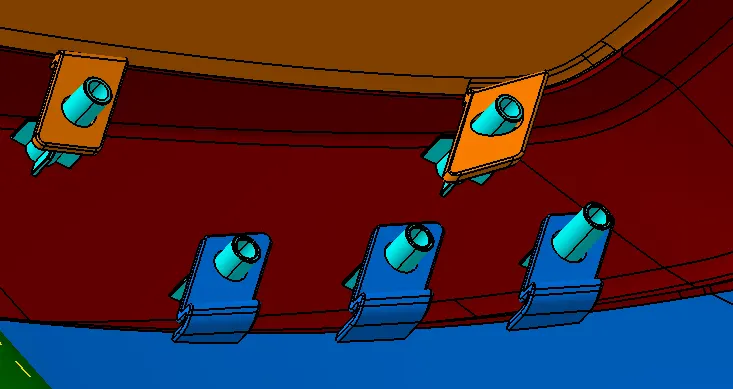
Thermal Staking or Heat staking is an assembly method that uses the controlled melting and reforming of plastic stud or boss to capture or lock another plastic or metal component of an assembly in place. The plastic stud protrudes through a hole in the component to be locked in place. The heated thermal tip contacts the top of stud, which melts and fills the volume of the tip cavity to produce a head, locking the component in place. The progressive melting of plastic under continuous pressure forms the head. When staking, the right combination of heat and pressure for the application is critical.
Heat staking also known as thermoplastic staking is the process of joining two dissimilar materials together. In heat staking we use local heating and cooling to raise the temperature of plastic components and allow plastic reforming to be carried out. This reforming can be used in a wide variety of applications.
Applications range from staking plastic boss’s for assembly of car door panels to joining PCB’s to plastic housings.
Advantages
- Simplification of machinery
- Reduced cost of machinery
- No vibration damage
- No particulates
- The ability to stake metalized coated applications
- The capability to stake in difficult to access or restricted areas.
- Multiple fastening points
- Allow higher density of welds compared to hot air cold form or ultrasonic welding.
Dog House
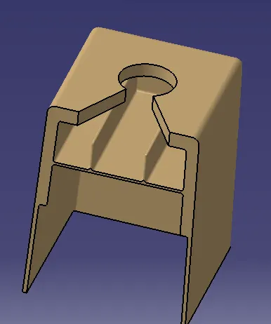
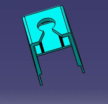
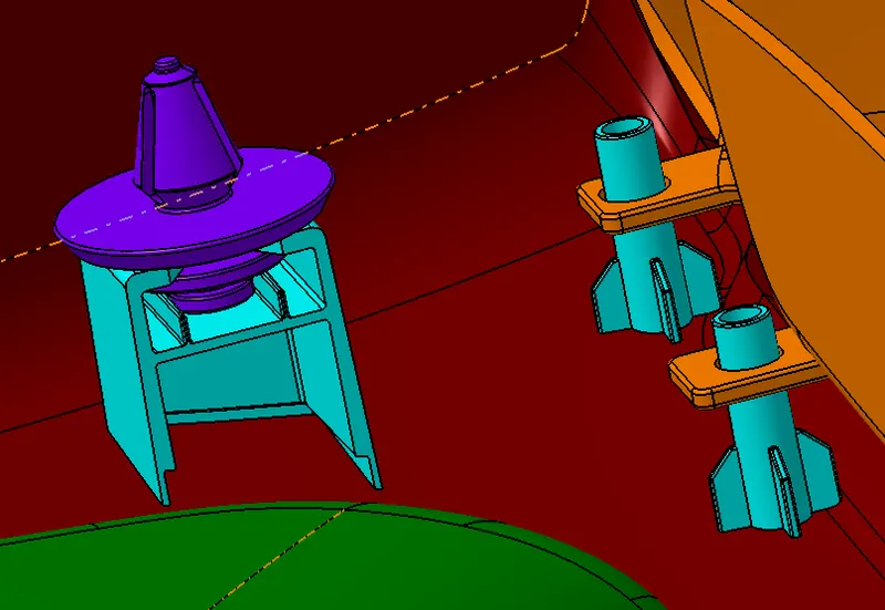
Dog house is an engineering feature used in plastic trim design. Dog houses are used as supporting feature. Sometimes other engineering features like snaps; locators etc. are mounded on them to increase their strength.
Dog houses are subjected to draft analysis to prevent breakage of the component during ejection from mould cavity. Dog house and other engineering components are built on B-surface.
Class A Surface: Class A surface is any of a set of freeform surfaces of high efficiency and quality. In other words, Class A surface is the aesthetic surface.
Class B Surface: Class B surface is the thickened suface or engineering surface where all ribs etc will come.
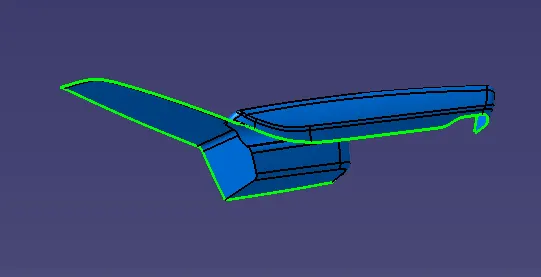
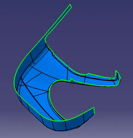
Class C Surface: It is the Surface which joins Class A and Class B surfaces.
SOFTWARE USED
Catia V5
DESIGN
Thickness, t : 2.5mm
ARM REST
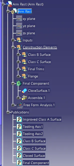
Tree Structure
Tooling Axis
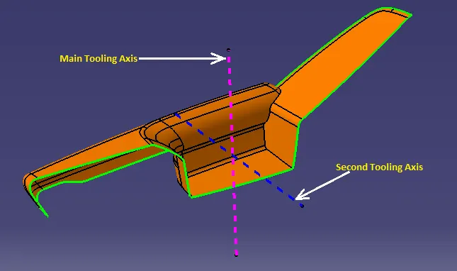
The surface is not fully clearing with main tooling axis, so we have provided second tooling axis such that it is clearing the draft.
Draft Analysis
Class A Surface

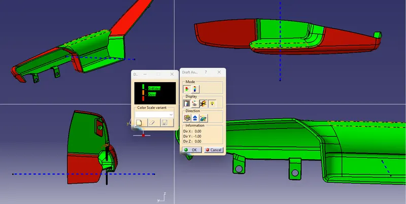
The surface is not fully clearing with main tooling axis, so we have provided second tooling axis such that it is clearing the draft.
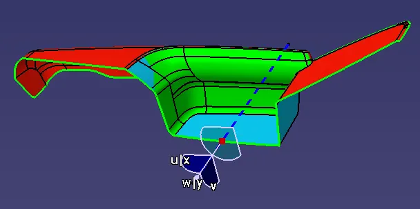
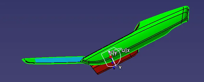
Closed Surface
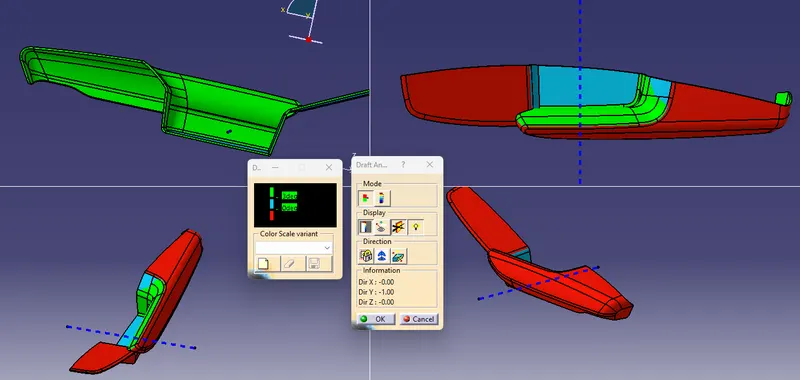
The red clear area will be cleared in main tooling axis.
Final Component
Class A Surface
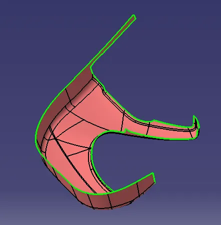
The given Class A surface was not properly finished and has some gaps. So in order to make it suitable for design we have repaired the given Class A Surface.
Class B Surface
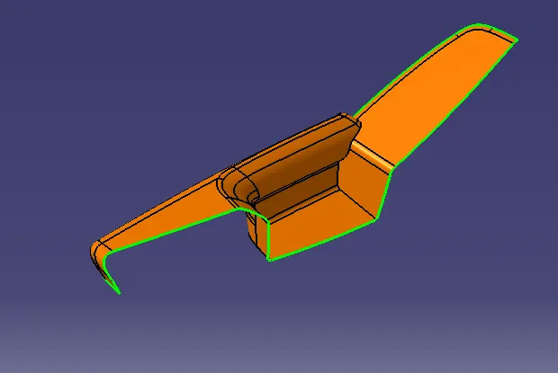
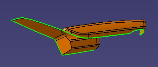
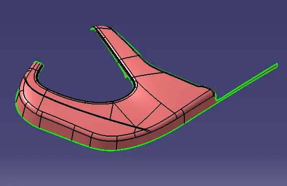
The Class A surface is offseted to 2.5mm to form Class B surface.
Class C Surface
Final Joined Surface
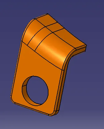
Flange
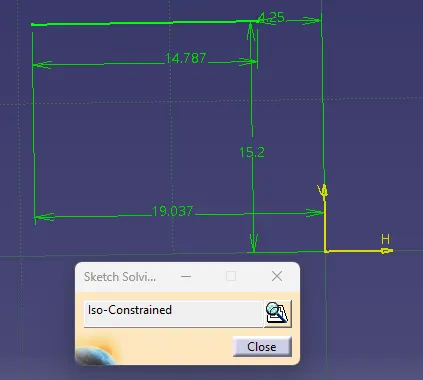
Sketch
3D Model
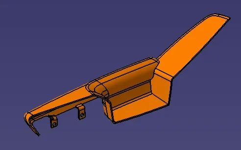
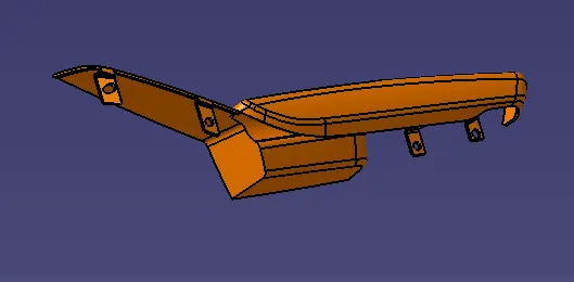
Final Component In Various Orientations
Isometric View
Front View
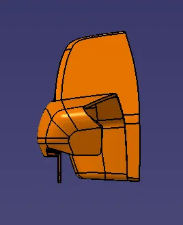
Back View
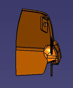
Left Side View
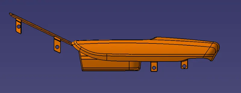
Right Side View
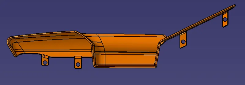
Top View
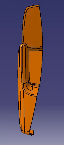
Bottom View
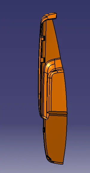
MAP POCKET
Thickness, t : 2.5mm
Tree Structure
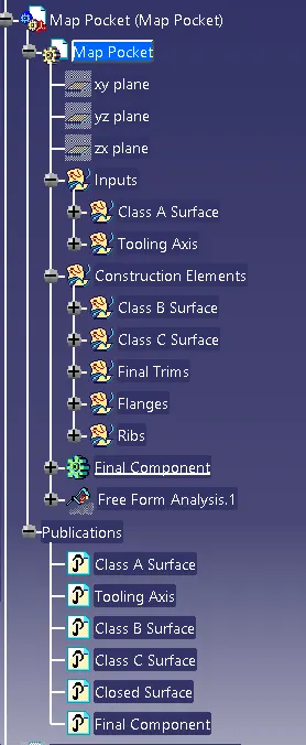
Tooling Axis
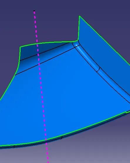
Draft Analysis
Class A Surface
The surface is clearing draft wit respect to main tooling axis.
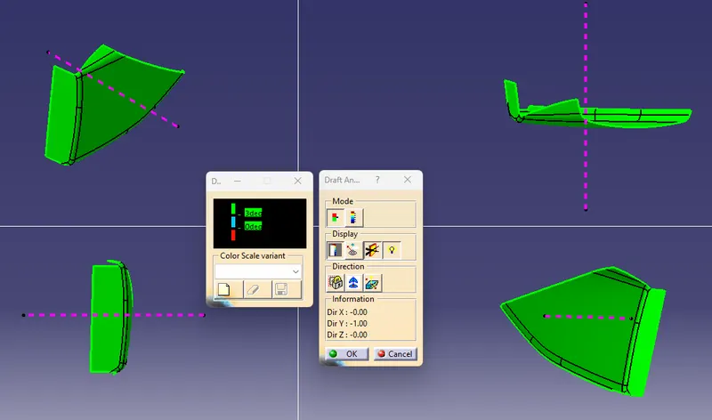
Closed Surface
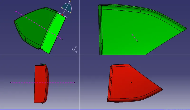
Final Component
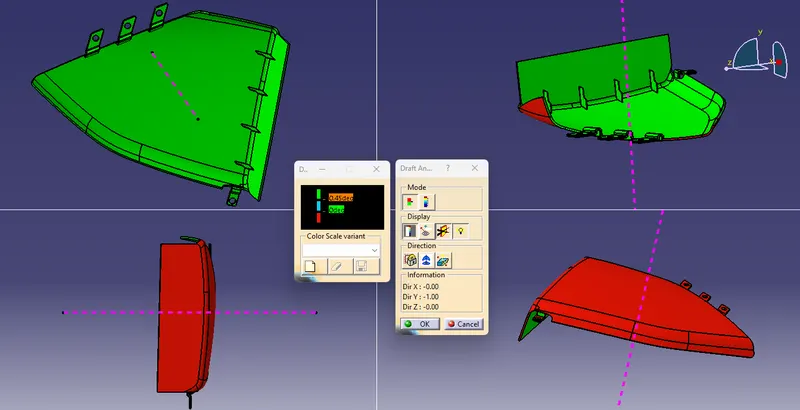
Class A Surface
The given Class A surface was not properly finished and has some gaps. So in order to make it suitable for design we have repaired the given Class A Surface.
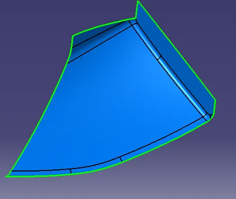
Class B Surface
The Class A surface is offseted to 2.5mm to form Class B surface.
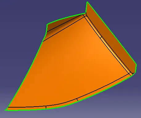
Class C Surface
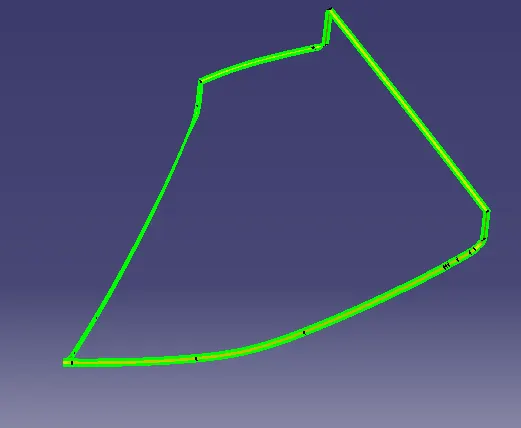
Final Joined Surface
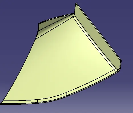
Flange
Sketch
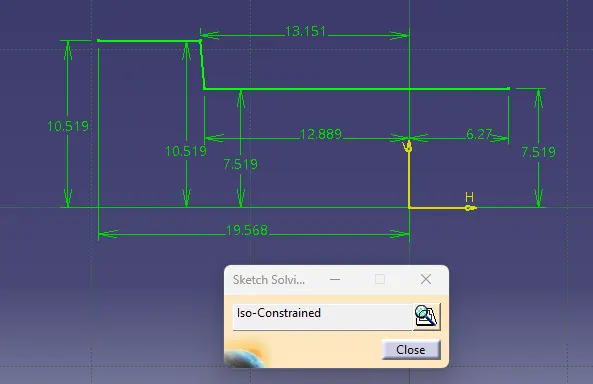
3D Model
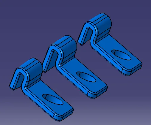
Ribs
Design
| Draft | `≥0.5^o`≥0.5o"> |
| Rib Thickness | 0.4 x t |
| Rib Thickness at Tip | `≥0.75mm` |
| Fillet Radius | 0.25 mm max |
| Rib Height | `≤5×t` |
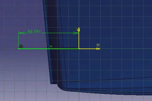
Sketch
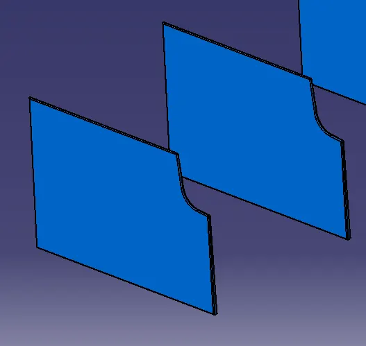
3D Model
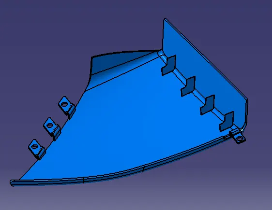
Final Component In Various Orientations
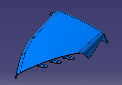
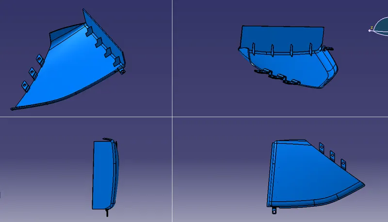
BOTTLE HOLDER
Thickness, t : 2.5mm
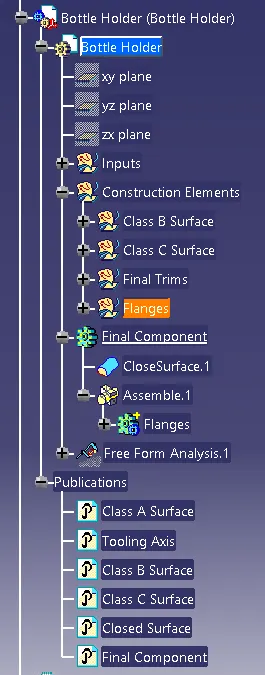
Tree Structure
Tooling Axis
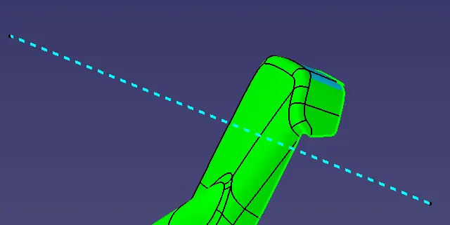
Draft Analysis
Class A Surface
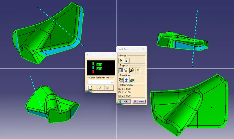
The given Class A Surface is not clearing draft fully, it has some negative draft in some of the areas. So we have to inform the Stylilng team to rectify this, but for this challenge purpose we are proceeding with this surface.
Closed Surface
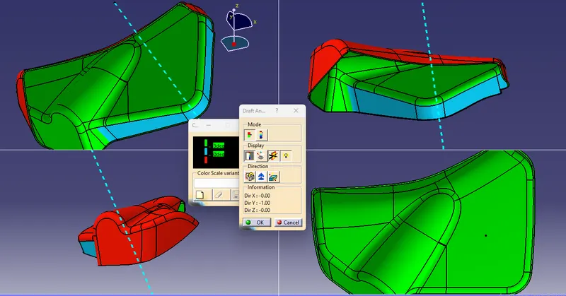
The Closed Surface is not clearing draft fully, it has some negative draft in some of the areas. So we have to inform the Stylilng team to rectify this. But the C surface formed is clearing the draft.
Final Component
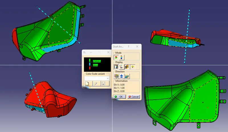
The Closed Surface is not clearing draft fully, it has some negative draft in some of the areas. So we have to inform the Stylilng team to rectify this. But the C surface and the flanges created are clearing the draft.
Class A Surface
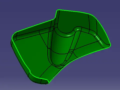
The given Class A surface was not properly finished and has some gaps. So in order to make it suitable for design we have repaired the given Class A Surface.
Class B Surface
The Class A surface is offseted to 2.5mm to form Class B surface.
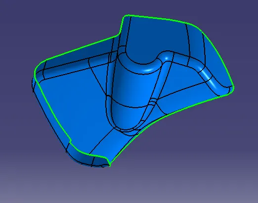
Class C Surface
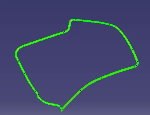
Final Joined Surface
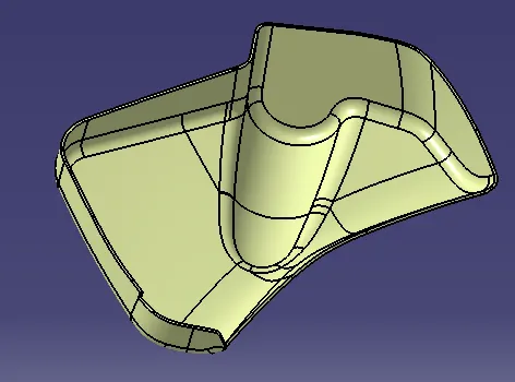
Flange
Sketch
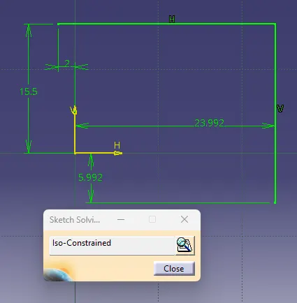
3D Model
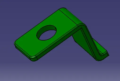
Final Component In Various Orientations
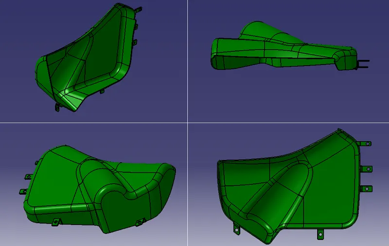
LOWER SUBSTRATE
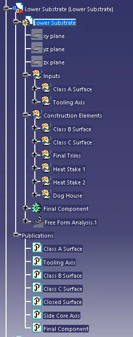
Tree Structure
Tooling Axis
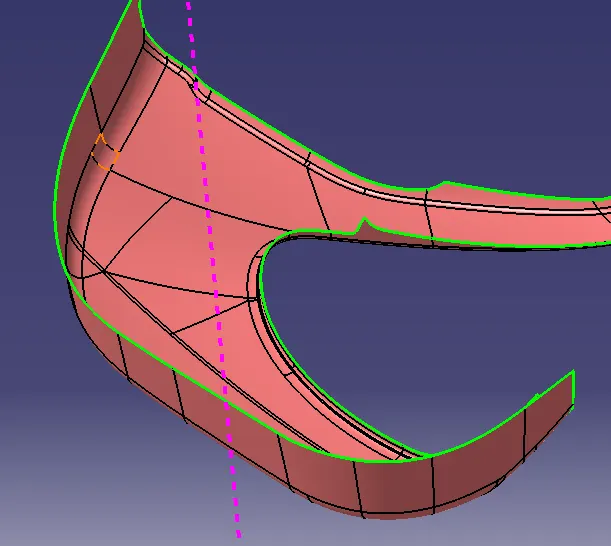
Draft Analysis
Class A Surface
The given Class A Surface is clearing the draft.
Closed Surface
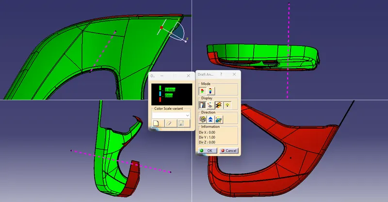
The Closed Surface is clearing the draft.
Final Component
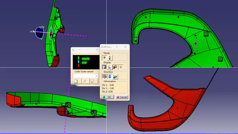
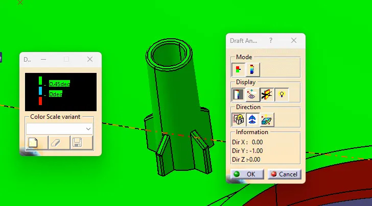
The final component along with the B side Features like Dog House, Heat Stakes are clearing the draft.
Dog House
For Clearing the draft of inside features in dog house a side core axis is provided.
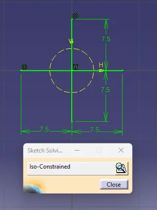
Heat Stakes
Class A Surface
Class B Surface
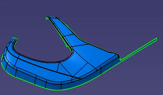
Class C Surface
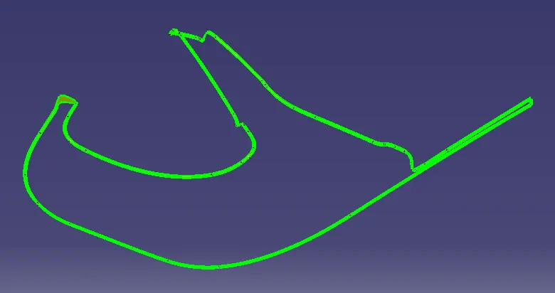
Final Joined Surface
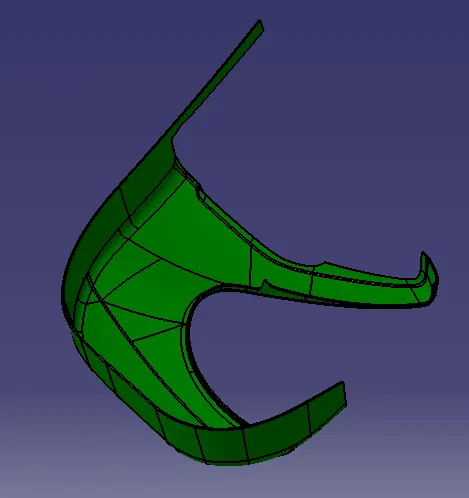
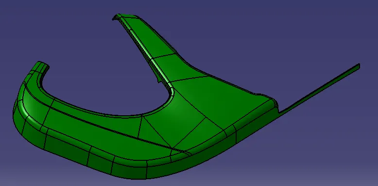
Dog House
Design
Thickness, t : 2.5mm
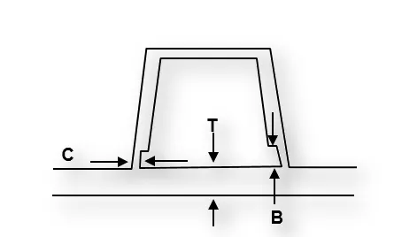
| C | `40%` of t or `≤ t` |
| B | 3 - 6 mm |
| Width | `≥12 mm` |
| Width to Height Ratio | 3:1 |
| Draft | `1.5^o` |
Sketch
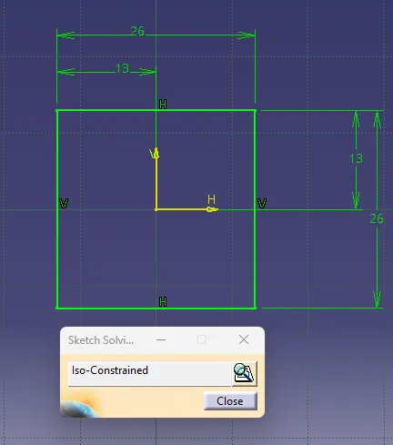
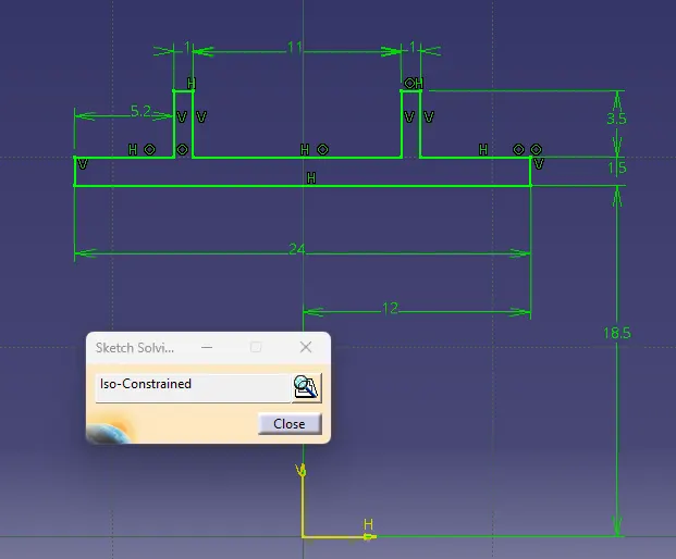
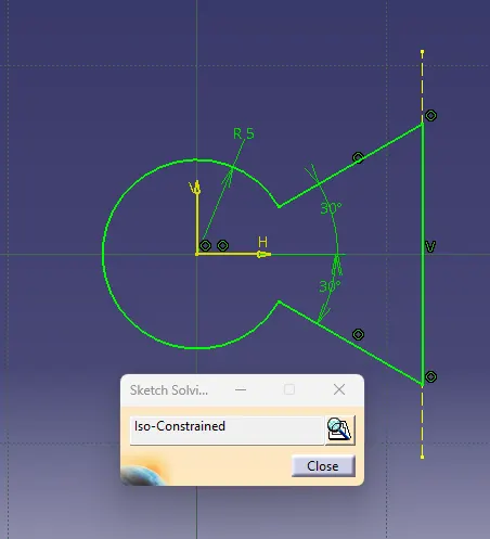
3D Model
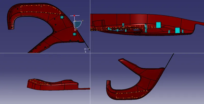
Heat Stakes
Sketch
3D Model
Final Component In Various Orientations
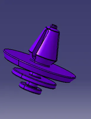
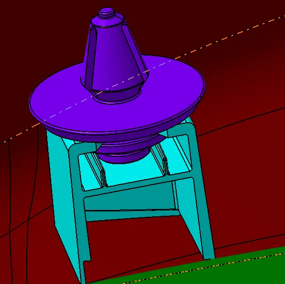
PUSH PIN
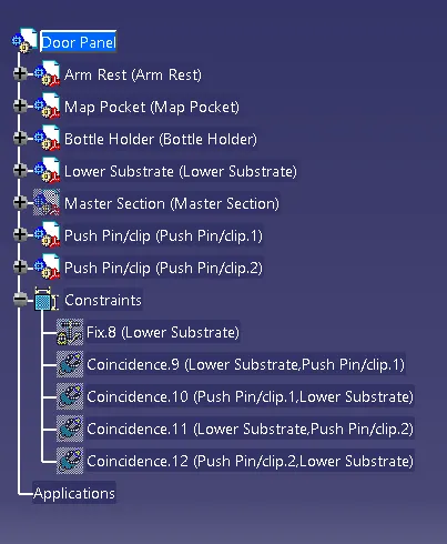
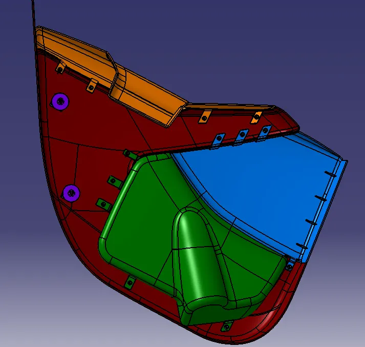
FINAL ASSEMBLY
Tree Structure
Isometric View
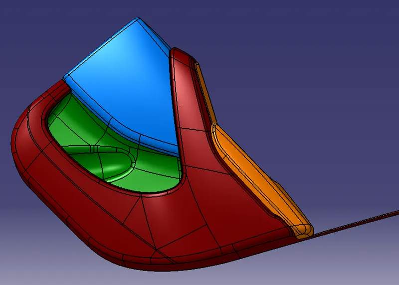
Front View
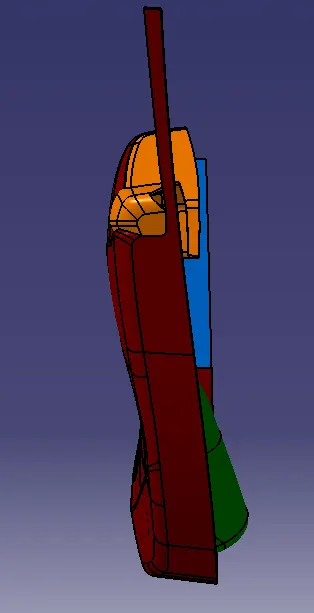
Back View
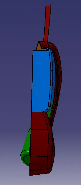
Left Side View
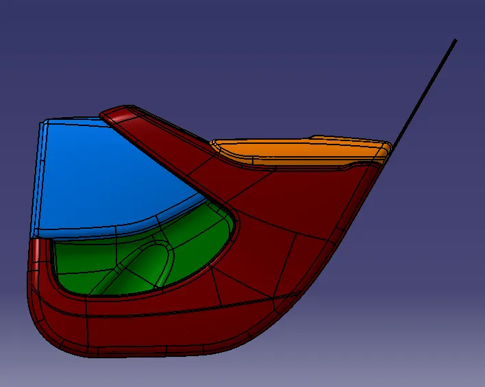
Right Side View
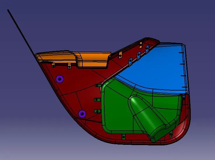
Top View
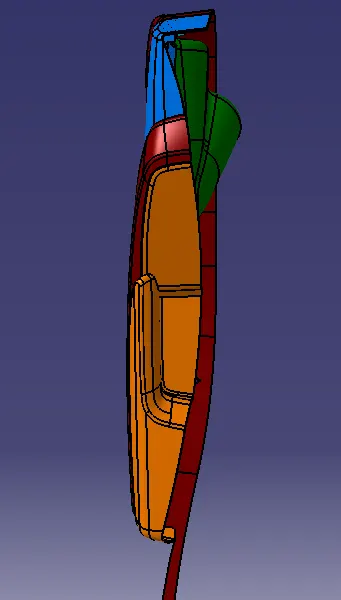
Bottom View
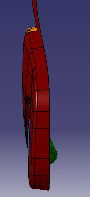
CONCLUSION
CAD model of a Door Trim panel considering the OEM standards has been created in Catia.