Week 12-Creation of 1D Connectors Challenge
1. AIM: Mesh the given Geometry & Creating the connector in assembly.
2. OBJECTIVES OF THE PROJECT:
Mesh the given Geometry as per given quality criteria and Create appropriate connections in between parts.
Target Element size - 5 Units
|
S.N |
Quality Criteria |
Value |
|
1 |
Aspect Ratio |
5 |
|
2 |
Skewness |
45 |
|
3 |
Warping |
15 |
|
4 |
Taper |
0.5 |
|
5 |
Min. Length |
2 Units |
|
6 |
Max. Length |
8 Units |
|
7 |
Min angle Quad |
45 |
|
8 |
Max angle Quad |
135 |
|
9 |
Min angle Tria |
30 |
|
10 |
Max angle Tria |
110 |
|
10 |
Tria % |
15 |
Create a connector and Attach the various parts of the given model
1. Right_Rail_2 & Front_truss_1:- Seam-Quad(angled+capped+L)
2. Left_Rail_2 & Front_truss_1:- Quad elements
3. Front_truss_2, Front_truss_1 & Right_Rail_1:- Spot weld with 2 Layers and 5 mm Diameter
4. Front_truss_2, Front_truss_1 & Left_Rail_1:- Hexa (Adhesive)
5. Rear_truss_2 & Right_Rail_2:- Bolt Connector
6. Rear_truss_2 & Left_Rail_2:- Bolt Connector
7. Right_Rail_1 & Right_Rail_2:- Spot-weld with Rigid Elements
8. Left_Rail_1 & Left_Rail_2:- Spot-weld with Spring Elements
9. Rest all the components left Join them with suitable connectors
3. BODY OF THE CONTENT:
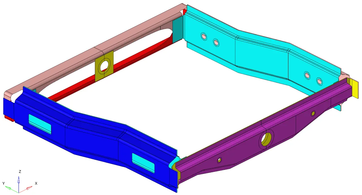
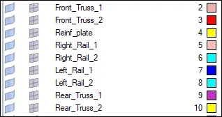
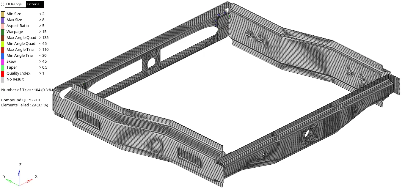
In this given model the mid-surface generation was already done(see the image). We can directly generate a mesh as per the quality criteria(see the image).
- CREATING A CONNECTIONS:
Now using a 1D > connector we are creating appropriate connections as per given.(see the below image)
1. Right_Rail_2 & Front_truss_1:- Seam-Quad(angled+capped+L)
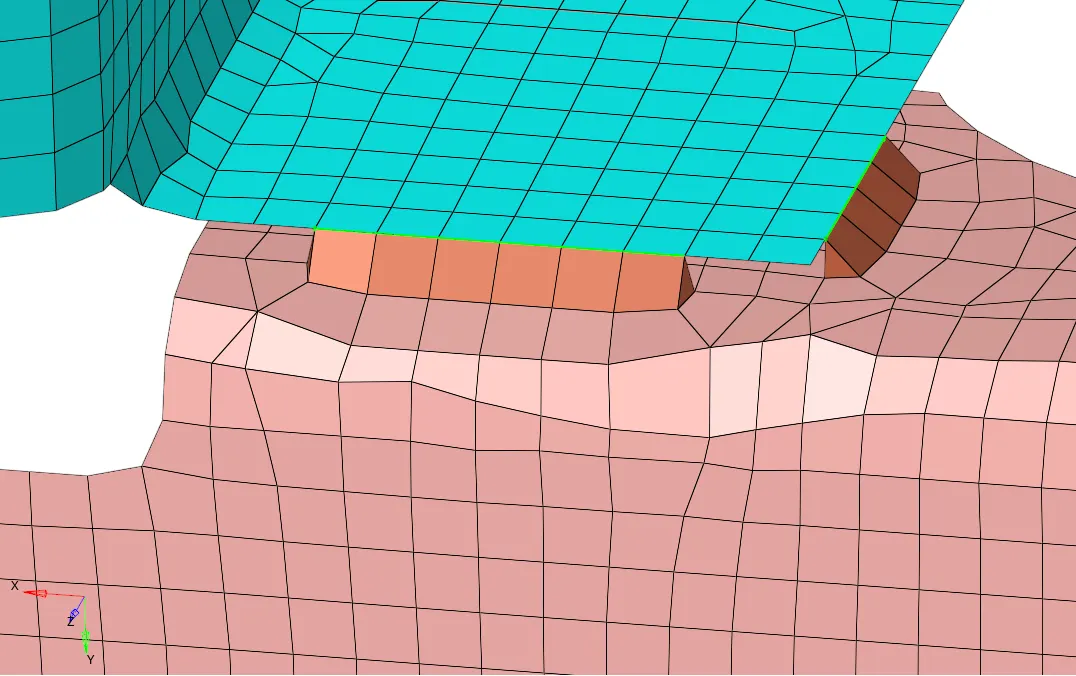

Whereas the average element size is 5. So the spacing value taken is 5. To realize the connection, tolerance value increased by 0 to 30. cap & weld angle remain default. and other values can be seen in the image.
2. Left_Rail_2 & Front_truss_1:- Quad elements
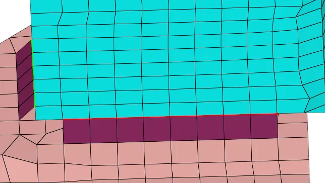

Here for quad elements, type-seam-quad(angled) selected. where the weld angle is 45.
3. Front_truss_2, Front_truss_1 & Right_Rail_1:- Spot weld with 2 Layers and 5 mm Diameter
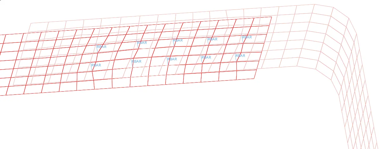

By 1D > connectors > spot command, where values like the type = weld, num. layer: total 2, diameter: 5 and other options selected as per image.
4. Front_truss_2, Front_truss_1 & Left_Rail_1:- Hexa (Adhesive)
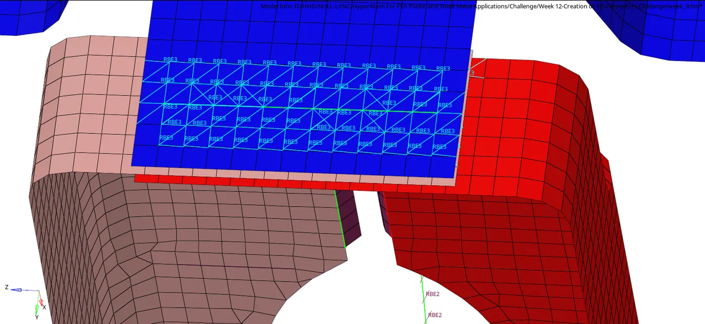
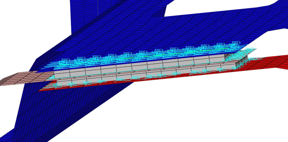

In a 1D > connectors > seam, there is an option for adhesive connection under Type= hexa(adhesive). where some node path selected and entered some values like strips= 4, coats= 2 & width= 20 and other options as per image.
5. Rear_truss_2 & Right_Rail_2:- Bolt Connector
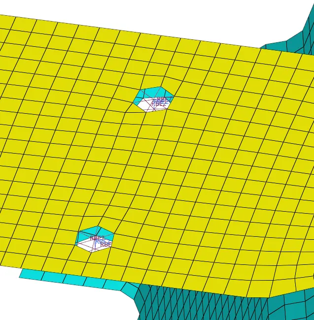
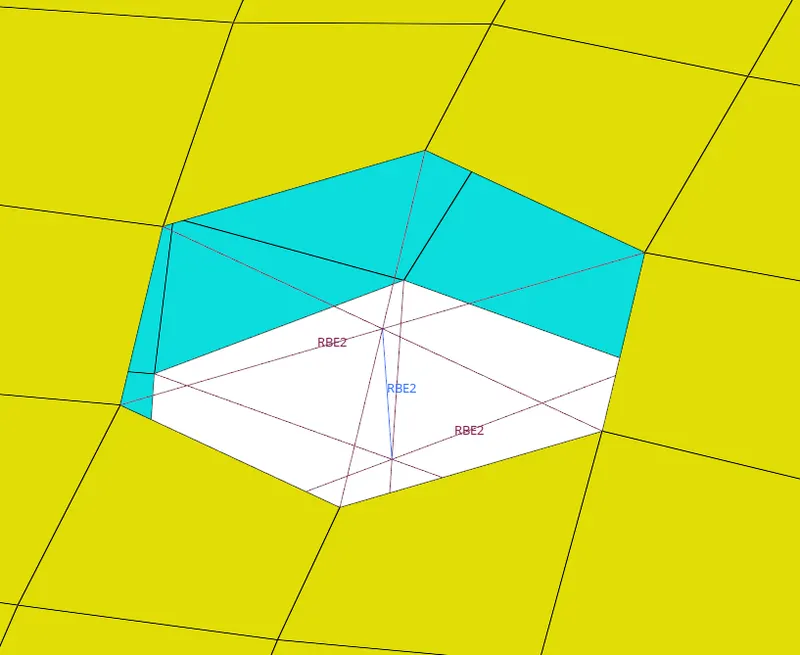

In 1D > connectors > bolt, we can create a bolt connection. where bolt type there are many options, but for now a type= bolt(general) is selected with 'create hole, if none' option. And other options as per image. With this it created RBE2 elements.
6. Rear_truss_2 & Left_Rail_2:- Bolt Connector
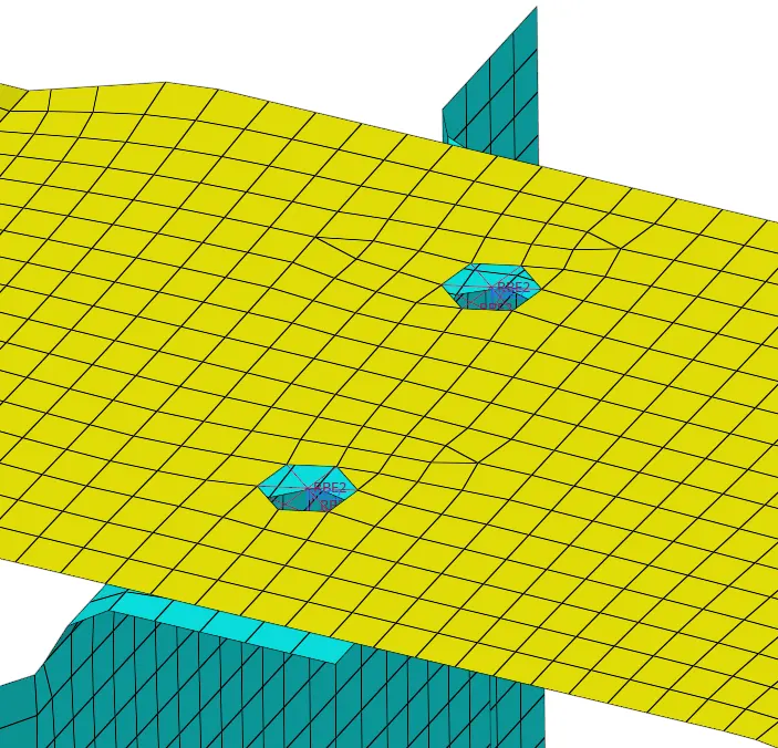
Same bolt connection is also done for Rear_truss_2 & Left_Rail_2 part connection.
7. Right_Rail_1 & Right_Rail_2:- Spot-weld with Rigid Elements
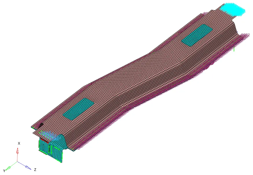
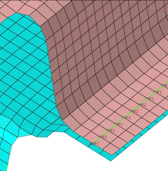
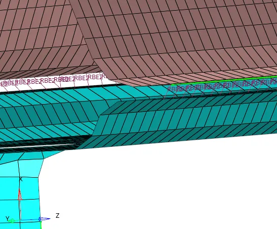

In 1D > connectors > spot choose type = rigid for 'Spot-weld with Rigid Elements'. and other details as per in image. We can see that a long spot weld seam was generated in the model. Hence its a rigid connection RBE2 elements are generated.
8. Left_Rail_1 & Left_Rail_2:- Spot-weld with Spring Elements
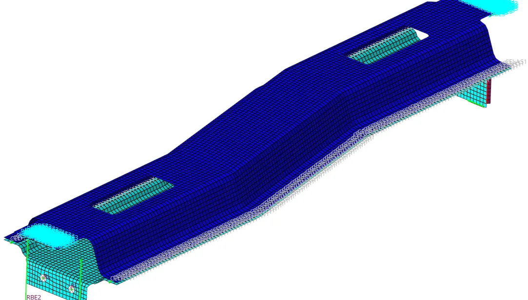
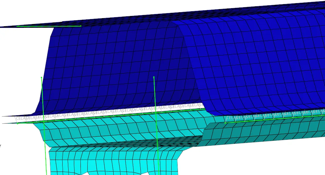

For 'Spot-weld with Spring Elements' we have chosen type= spring in '1D > connectors > spot'. can see in the images it has created a CELAS element for elastic behavior of spring.
9. Rest all the components left Join them with suitable connectors
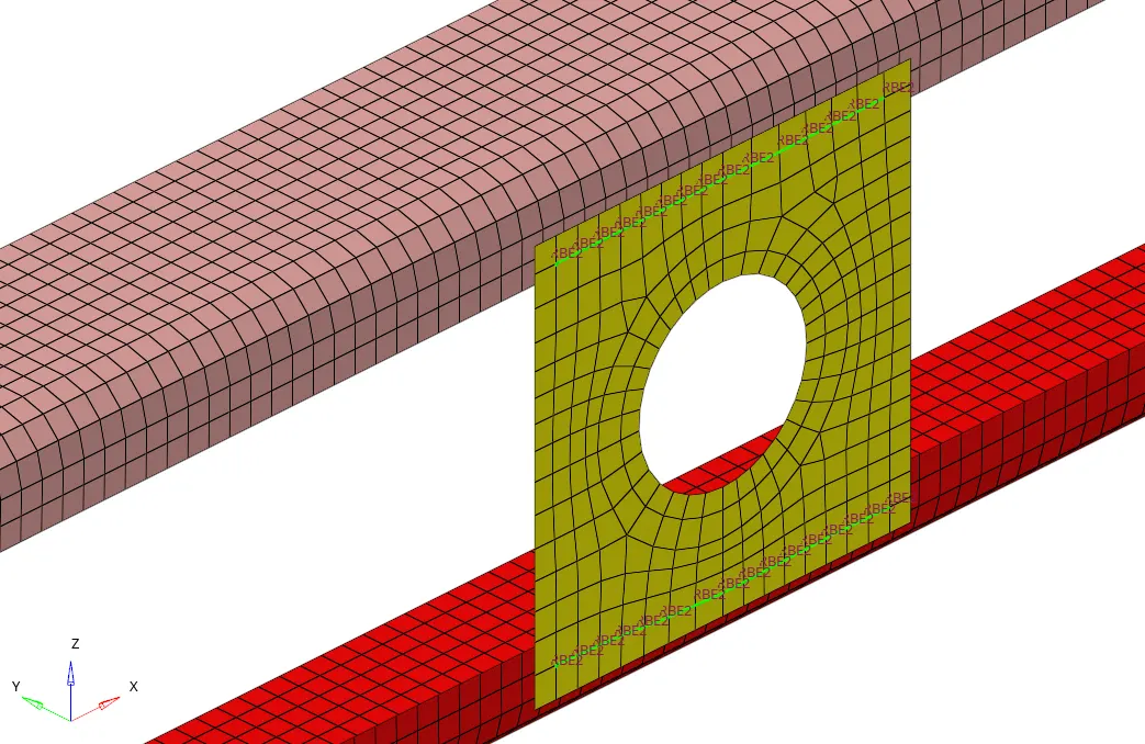
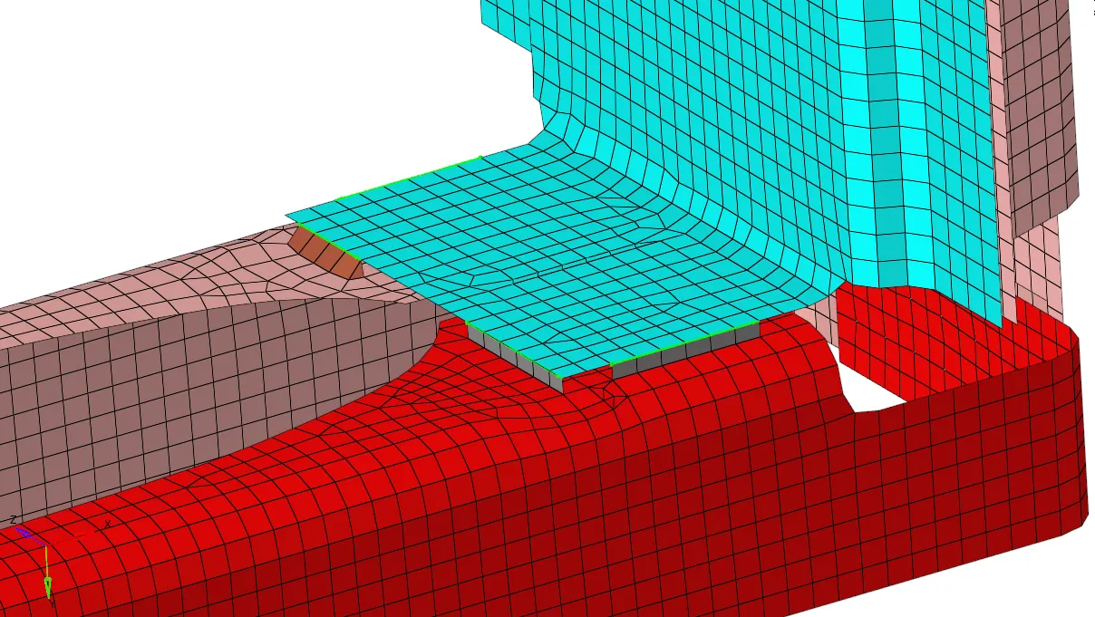
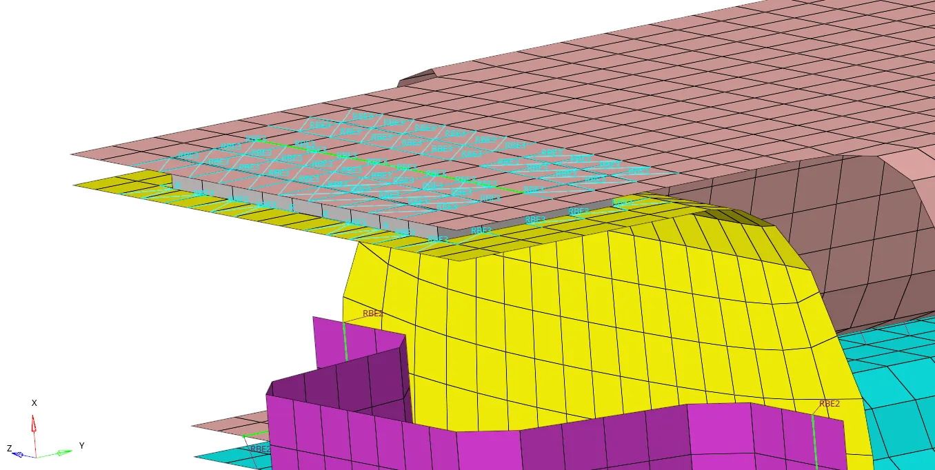
We can see in the above images that the rest of the connections are created & realized successfully. Like Spot weld, Adhesive and seam weld.
4. CONCLUSION:
The challenge is completed for given geometry. Mesh is generated & Connections are created. With this challenge I learn that for 1D connection how to ensure the connection of 1D element with one to one node. How to realize the connections. How to modify it and more.
End of Challenge