WEEK 12- CHALLENGE - OUTPUT FILES
Question
Using the provided PCB
- Generate a 3D file.
- Generate BOM and X Y Data.
- Generate Draftsman to show PCB assembly and manufacturing information.
- Generate output job as explained in the course.
Your Answers
AIM:
- To Generate a 3D file.
- To Generate BOM and X Y Data.
- To Generate Draftsman to show PCB assembly and manufacturing information.
- To Generate output job as explained in the course
PROCEDURE:
1.3D file:
Altium had a feature called 3D model to virtually see the designed components in 3 dimensional view before fabrication to analyse the shape of the object.
By pressing the key 3 we can enter into the 3d viewer.
To view the components in 3D we need to add 3D body for every individual components
3D body will be stored as step file, they can be generated by different methods
First method:
we need to select manage 3d bodies option in tools
For selected objects there will be some 3d bodies will be available we can choose according to our object
once we save the project we can get the 3d body for that components.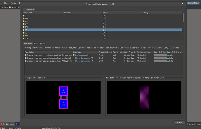
Second method:
we can download the 3d body from manufacturer website
After downloading the step file we can add that by using 3D body option
once its done we can customize the shape and fit it accordingly
By following the steps we can create the 3D body for that component
Lets see how to add the 3D step file for ATMEGA328
Step 1: search for ATMEGA328 3D stepfile in google.
Step 2: enter the website and download the particular step file.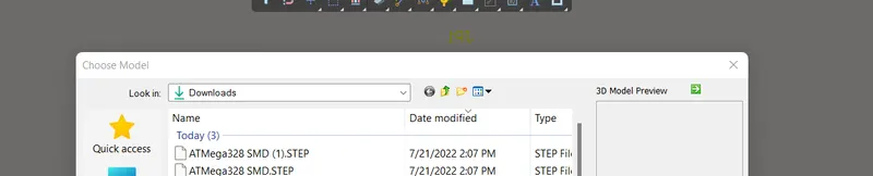
Step 3: once it was downloaded, click the ATMEGA328 component in pcb and select the 3D body option in toolsbar section.
step 4: After selecting 3D body it will ask us to navigate to the file location.
step 5: select the particular step file, so it will be imported into the pcb.
Step 6: After importing use the rotation option from properties to fit the 3D body in perfect position with ATMEGA328 component in pcb.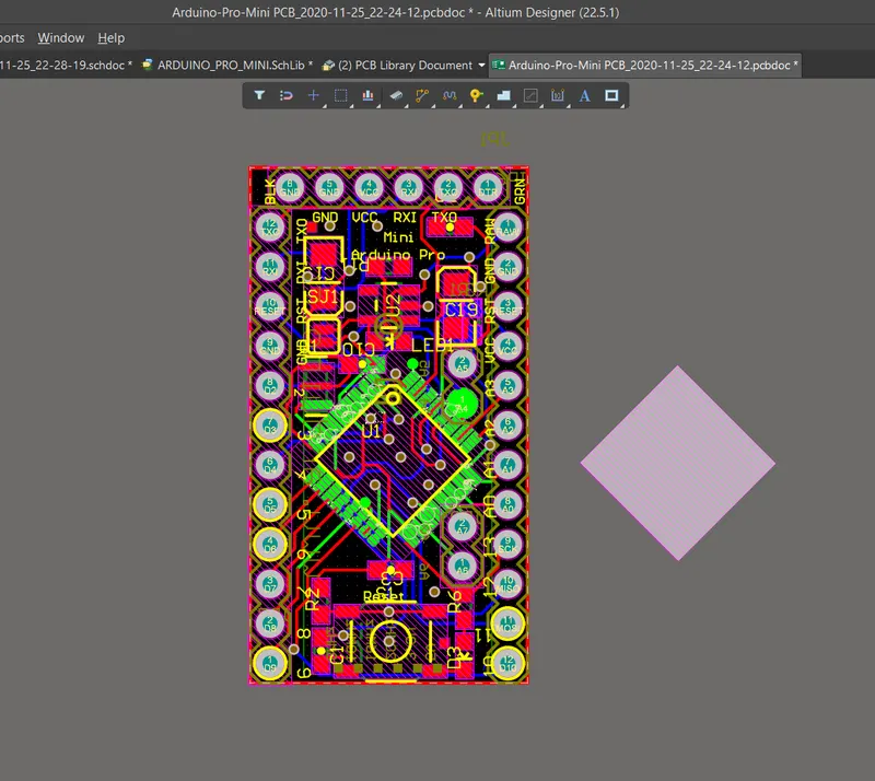
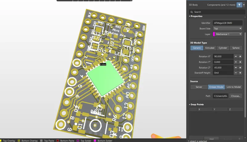
Step 7: once its completed we can click key 3 to view the 3D body of ATMEGA328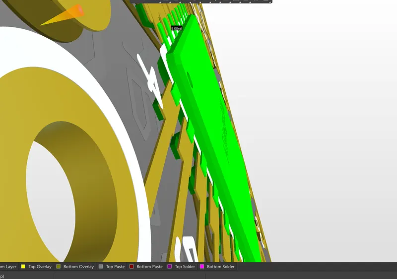
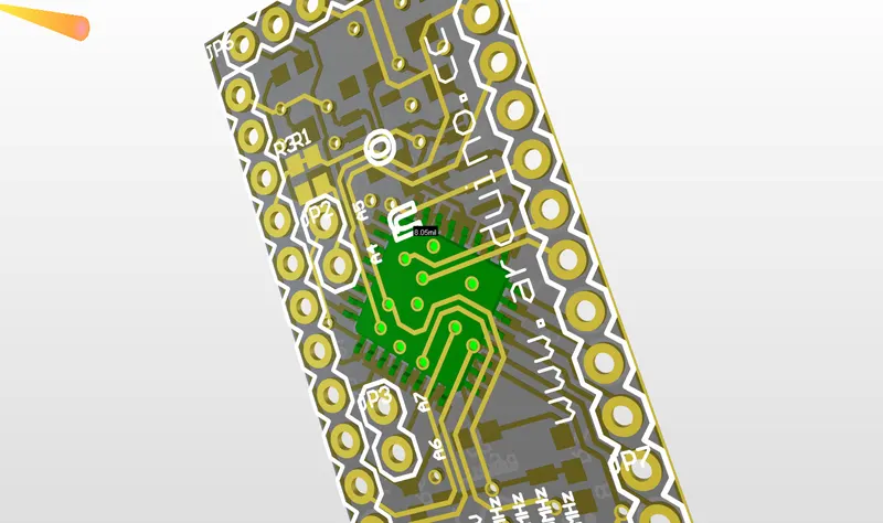
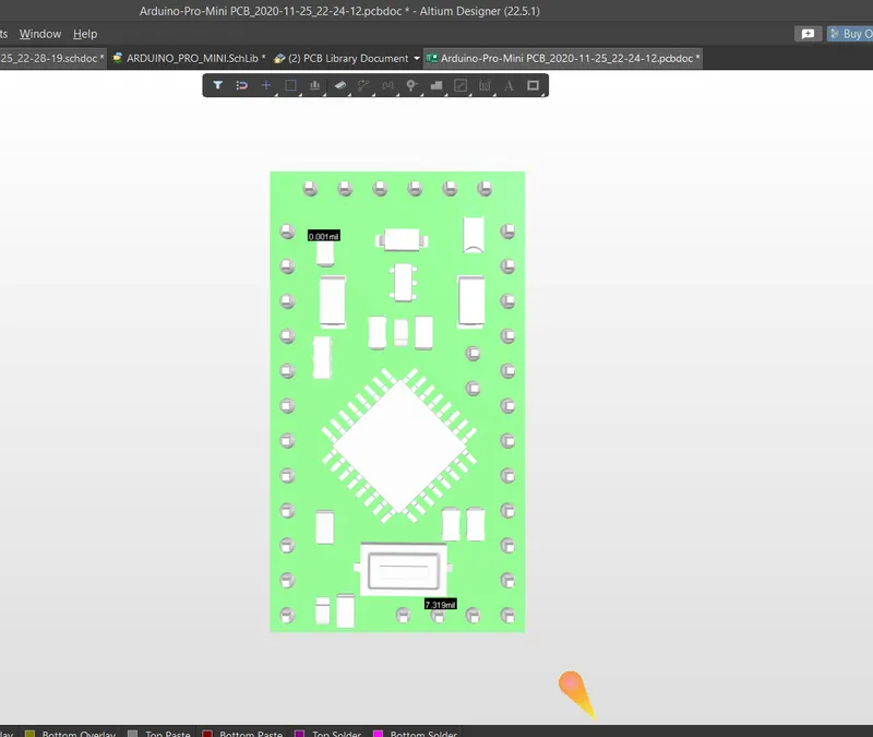
similarly we can create that all components in tha circuit to get the final step file for 3d body.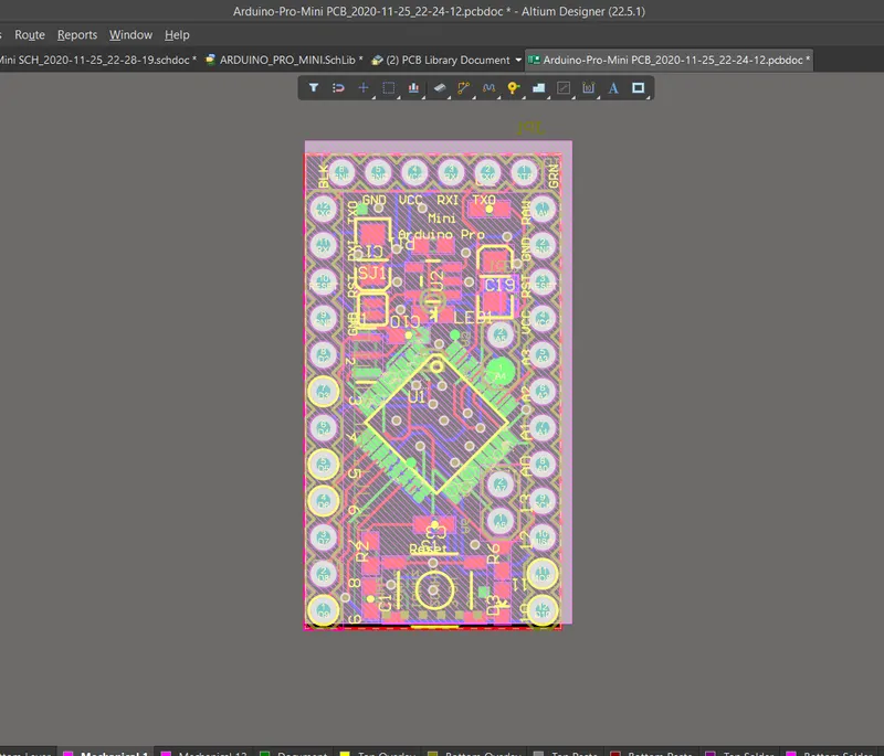
2.1 BILL OF MATERIALS:
Altium has a inbuild feature to calculate the bill of materials for each and every components.
step 1: To create bill of materials, At first we need to enter into the schematic sheet in project.
step 2: in the sheet we need to check the presence of supplier link in properties for each and every component.
Step 3: Start with any one component at first and select the component in sheet and click properties.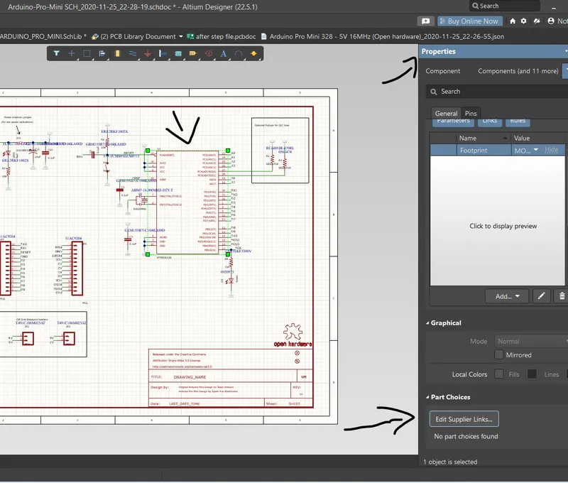
step 4: scroll down in properties section in the down section we can see the suppiler link area.
Step 5: click the section to add the link.
Step 6: once we clicked it will take us to the manufacture part search window.
step 7: in that window it will automatically search for related components.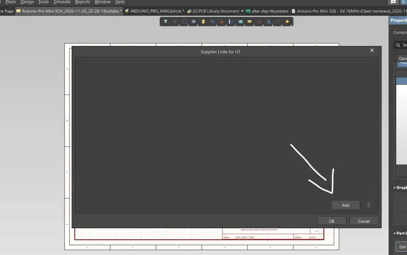
step 8: There will be number of components will be shown with dfferent manufactures, we need to find the manufacture who sells for best price, who has better minimum order quantity, and finally the stocks availablity.
step 9: depending upon this factors we need to select the supplier link to attach with the component.
Step 9: For a single component we can two or more suplier links.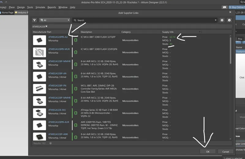
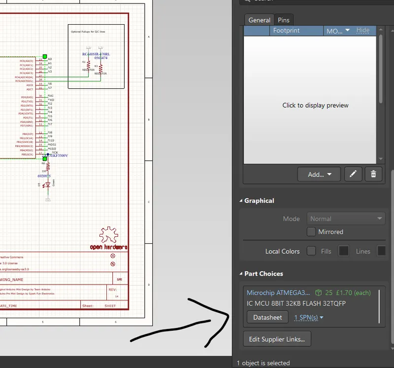
Step 10:The process will continous till all the components are connected with supplier links.
Step 11:After completing this process select bill of materials in report section
Step 12:select the list of things which we need to view there.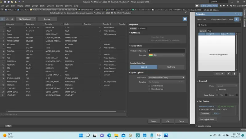
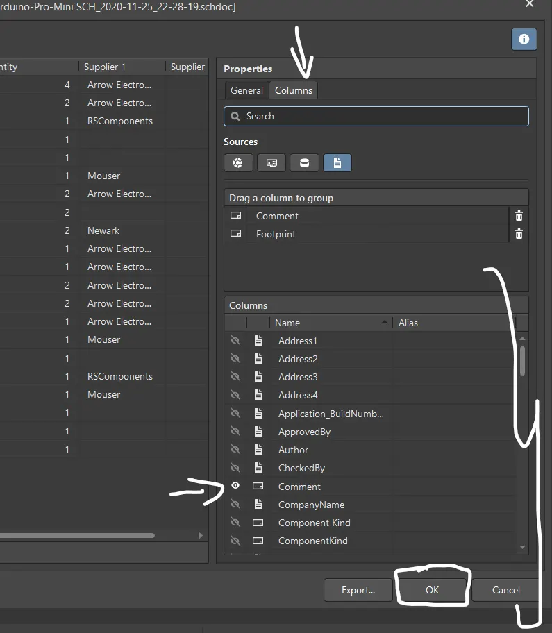
step 13:set the currency to inr, and enter the production quantity.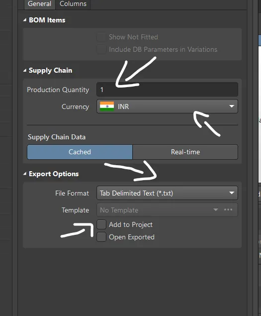
step 14:once the process was completed we can select preview to view the BOM.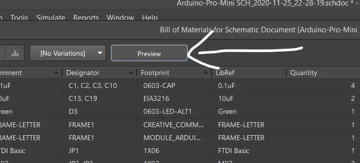
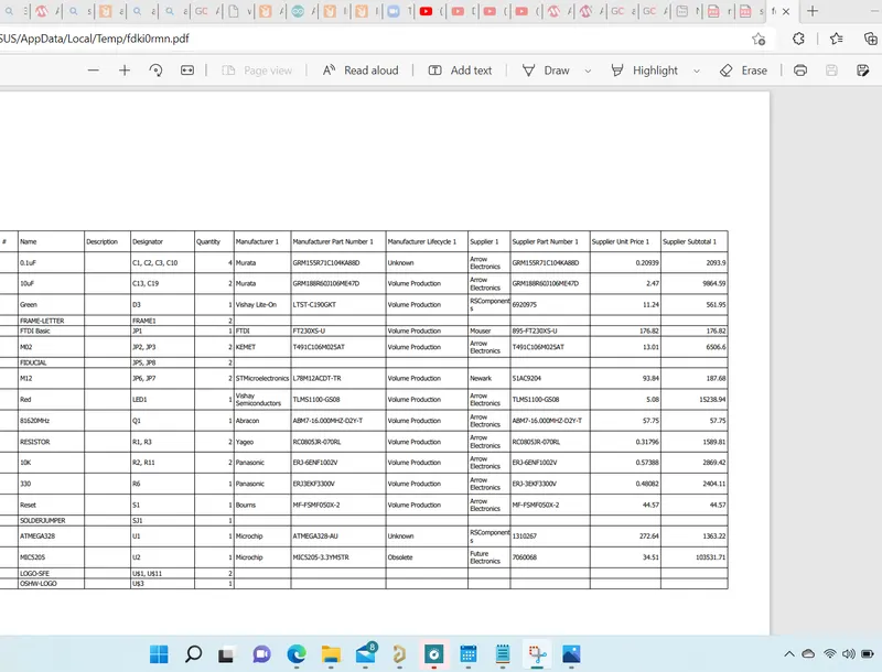
Step 15:if the BOM works file select Add to project, and select real time to get auto updated every time.
Step 16:now the BOM is created. using the item manager we can check the components status every time.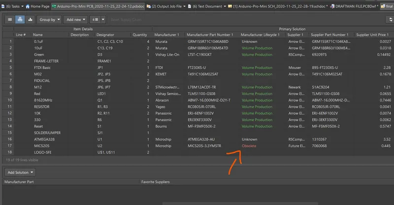
Step 17: now the above shown component is shown as obsolete, it means their is no stock from the selected supplier.
step 18: in this case we need to change the supplier, so it can be sorted out.
2.2: X AND Y DATA :
After completing the design phase the pcb will send for fabrication and assembly, there the process will be done based on the x & y axis
Step 1: Add the fiducials in the corners of the board
Step 2: Use one fiducial placed in the pcb to set as origin.
Step 3: select Edit > origin > set. and place the origin icon in fiducial.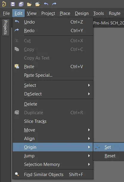
step 4: Then select File > assembly > pick and place.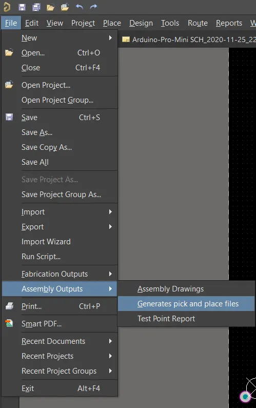
step 5: A window will popup, customize the things which we need to view and click metric, and text format as output.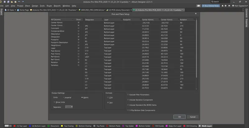
step 6: After doing this process click ok to generate the pick and place file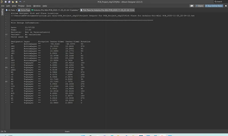
3.Draftsman:
Using draftsman we can crreate a file to show the details like stackup layer, nc drill, etc in a single file.
Step 1: select the project, and click add new project > draftsman document.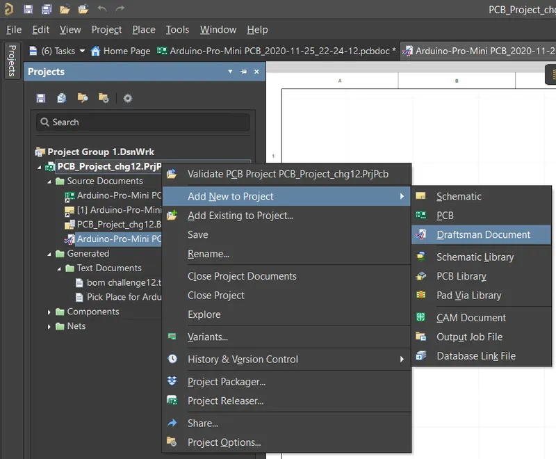
step 2: An pop up wise rise to select the pcb project, templates, etc
Step 3: draftsman has some default templates, and if we need to create we can create our own template.
step 4: once the template is fixed the file will pop up.
step 5: At first we need to set parameters in the bottom table section.
step 6: after the process using the place icon we can add the things which we need to be present in the draftsman document.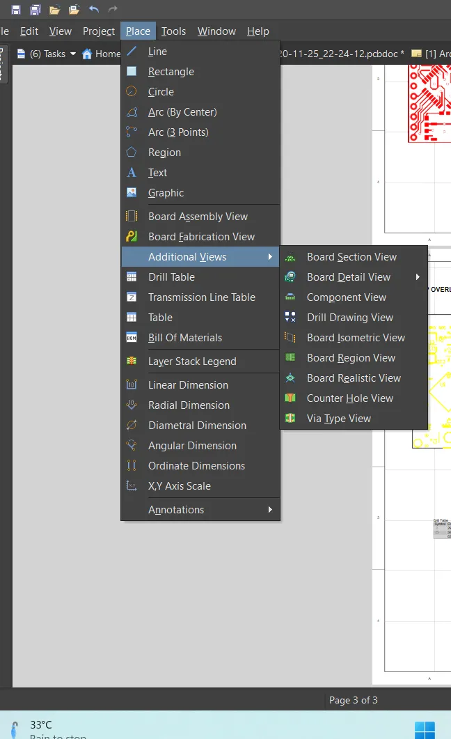
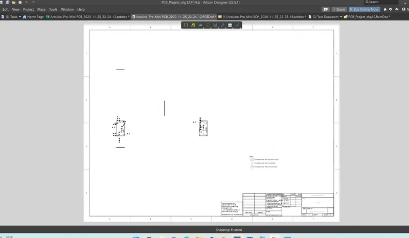
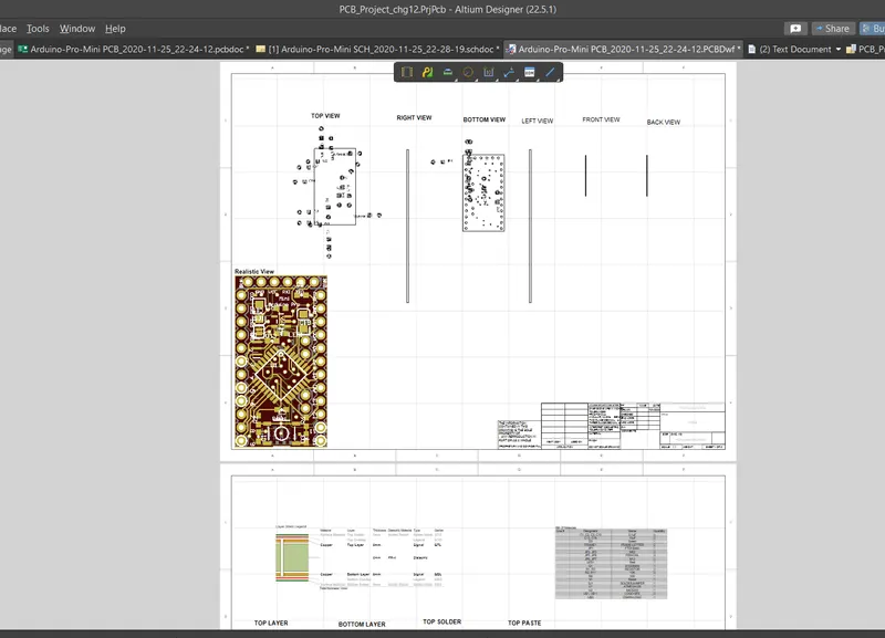
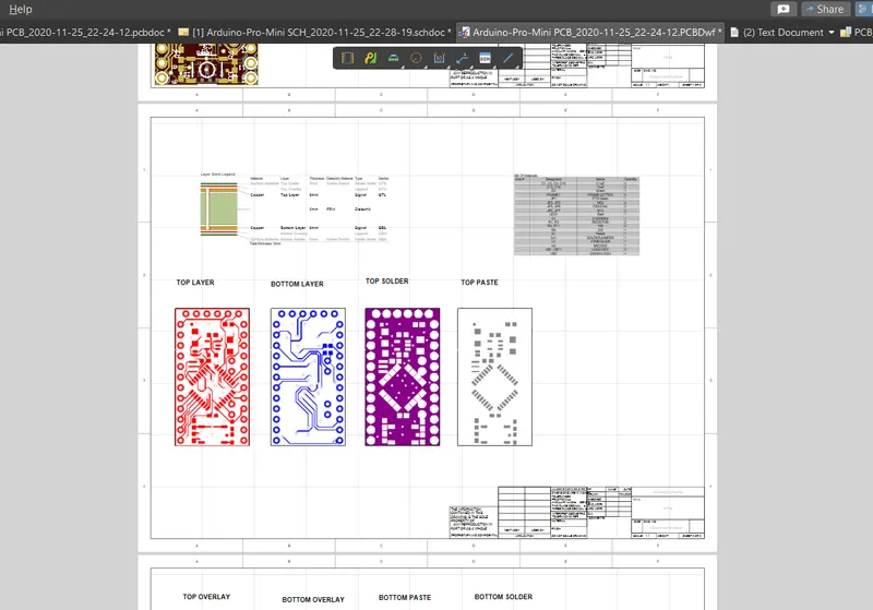
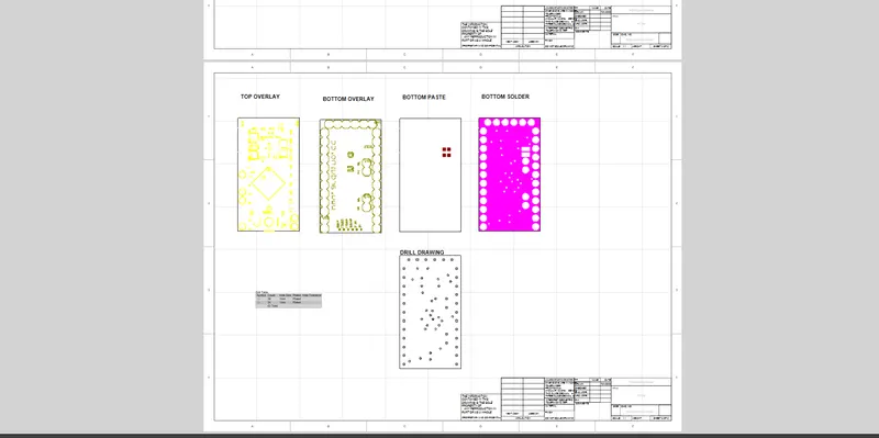
step 7: Finally save the project.
4.OUTPUT JOB:
step 1: select for output job and open the window.
Step 2: There will be lot of sections will be available to add the reports, add the reports in particular areas like assembly, etc.
step 3: Once the files was succesfully added, using the different options in right side like pdf, folder and video, categories the reports.
step 4: After this process generate the files added in right individually to see the final reports of output.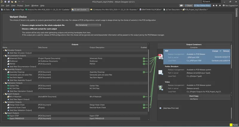
RESULT:
- Generated a 3D file.
- Generated BOM and X Y Data.
- Generated Draftsman to show PCB assembly and manufacturing information.
- Generated output job as explained in the course