Week 12 Challenge
AIM OF THE EXPERIMENT:
To determine the Barge Impact load acting on bridge and analyze accordingly in Staad.Pro.
THEORY:-
Barge Impact Load:-
- Barge impact is a potential hazard for bridge piers located in navigation waterways. The dynamic impact process is influenced by many factors, including barge mass, impact velocity, oblique impact angle, water elevation, material properties of pier members, soil properties, etc
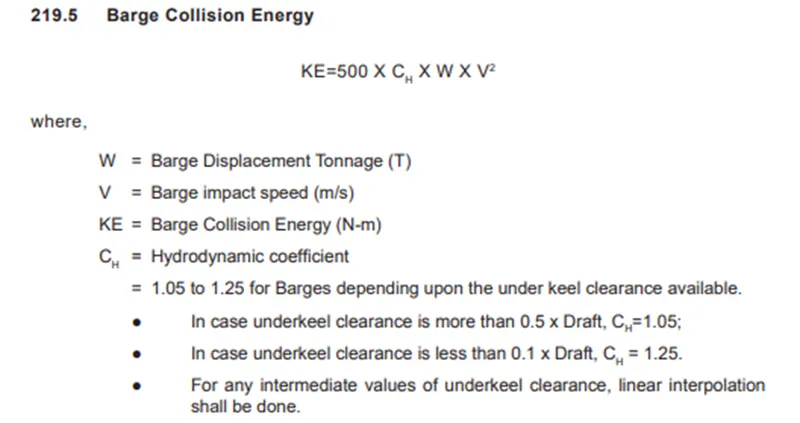
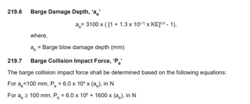
Given Data :-
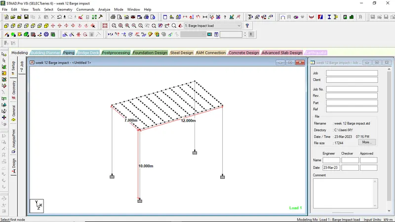
Span of bridge = 12.0 m
Width of carriage way = 7.0 m
Dead Weight tonnage of Panamax vessel = 52500 Tons
Maximum accommodation by ship = 4500 containers
Each container = 6.1 TEU
Speed of Barge = 60 km/hr
Size of Pier = 2.5 m x 2.5 m
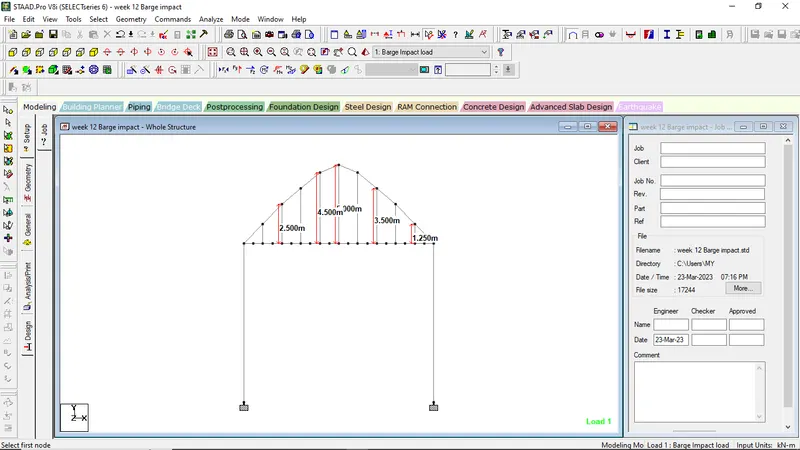
Rise of Bridge = 5.0 m
Thickness of deck slab = 500 mm = 0.5 m
Size of Cross beam = 0.75 m x 1.8 m
Hydrodynamic Coefficient (CH) = 1.25
Let us Assume that:
Size of Main Girder Beam = 0.75 m x 1.8 m
Size of the Truss member (Bracing and Vertical Strings) = 0.3 m x 0.3 m
Height of the pier=10m
Analytical Calculation:
All the loads are calculated in such a manner as mentioned below,
Hydrodynamic Coefficient (CH) = 1.25
Barge Displacement Tonnage = 52500 DWT
Barge Impact Speed (V) = 60 km/hr. = 16.67 m/s
Barge Collision Energy (KE) = 500 x CH x W x V2 = 500 x 1.25 x 52500 x (16.67)2 = 9118229531 N-m = 9.12 x 10⁹ N-m
Barge Damage Depth, aB = 3100 x ([1 + 1.3 x 10⁻⁷ KE]0.5 -1) = 3100 x ([1 + (1.3 x 10-7 x 9.12 x 109)]0.5 -1) = 103685.89 mm
Since aB > 100 mm
Then, Barge Collision Impact Force (PB)
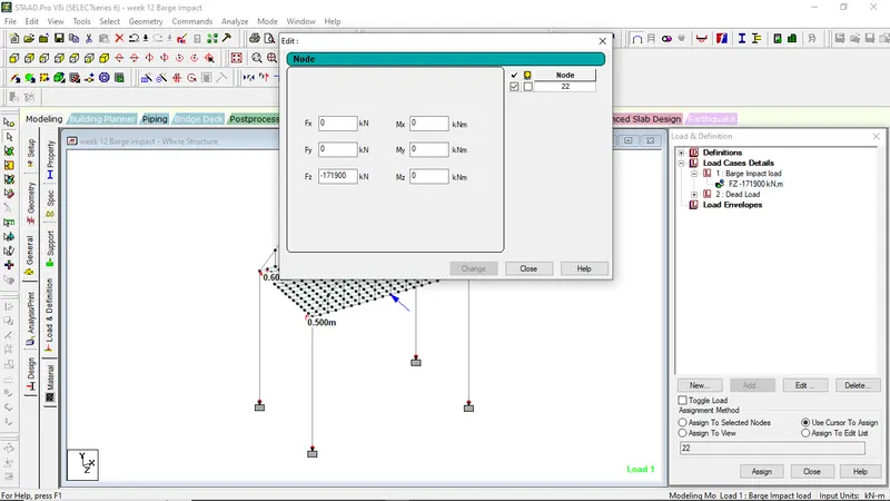
PB = 6.0 x 10⁶ + 1600 x aB = 6.0 x 10⁶ + 1600 x 103685.89 = 171897424 N = 171900 KN
PROCEDURE IN STAAD:-
STEP 1:
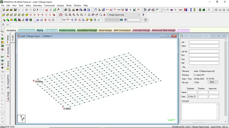
Model a rectangle of 7m x 12m i.e carriage way and span and pier of height 10m
Now as per question model the ox bow truss model with rise height of 5m,4.5m, 3.5m, 2.5m and 1.25m simulatanously on both the side
Now for the deck slab mesh element, take unit element as 0.6m x 0.5m
STEP 2:-
Assigning of Properties:-
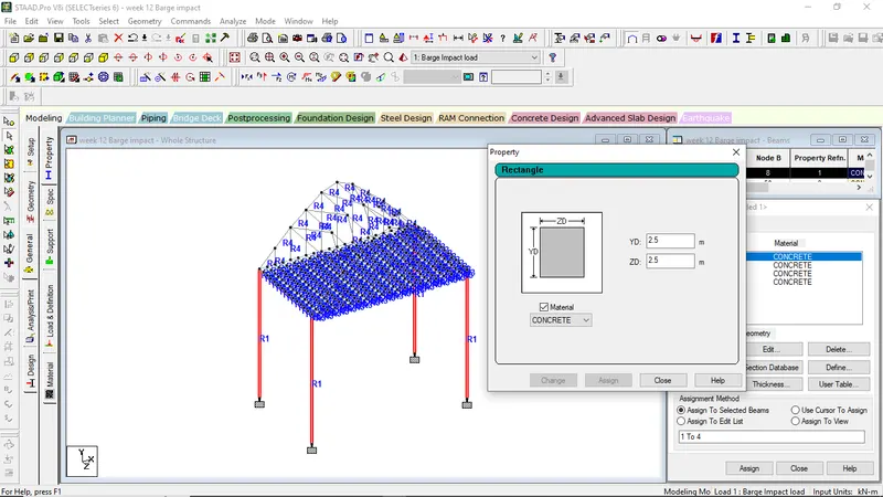
For Piers size 2.5m x 2.5m
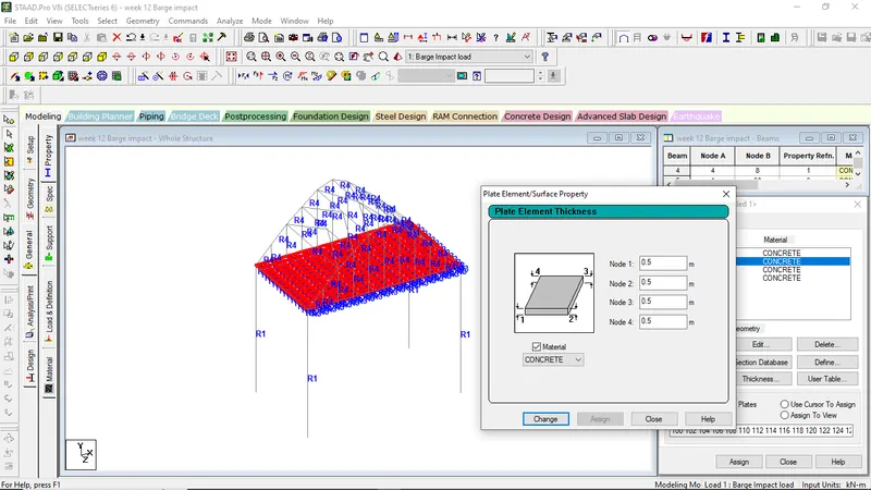
For Deck Slab 0.500m
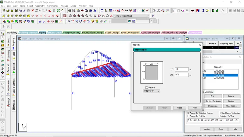
For Girders and Cross Girders size = 0.75m x 1.8m
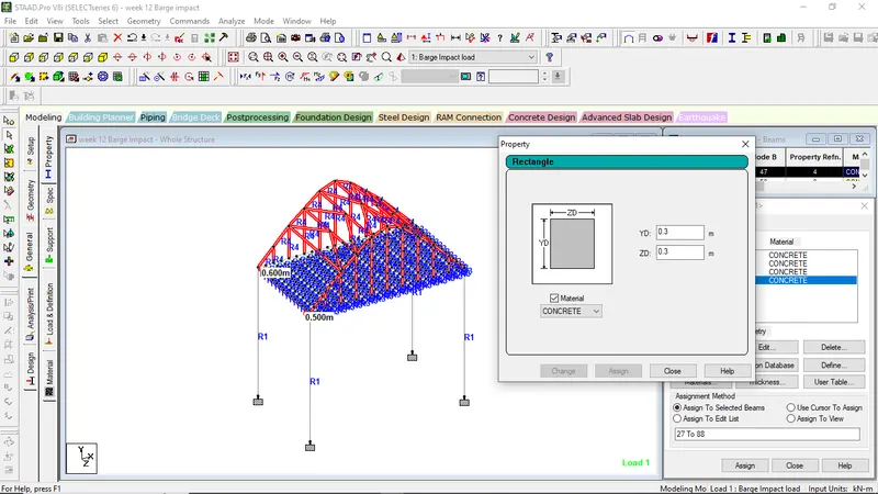
For Truss Elements size 0.3m x 0.3m
STEP 3:-
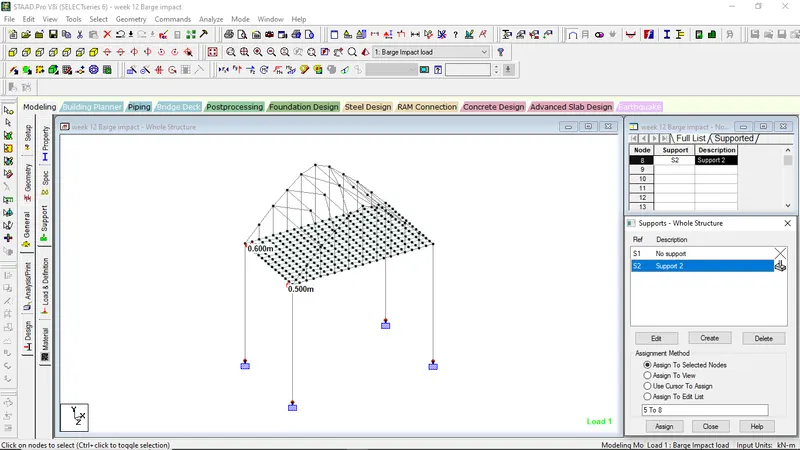
Support assignation
Step 4:-
- Assigning of Barge Impact Load to the Structure:-
- Go to Loads and Defination
- Click on Load Cases Details
- Click Add
- Rename Barge Impact Load
- Select on Barge Impact Load
- click Add
- Give the Nodal load value
Step 5:-
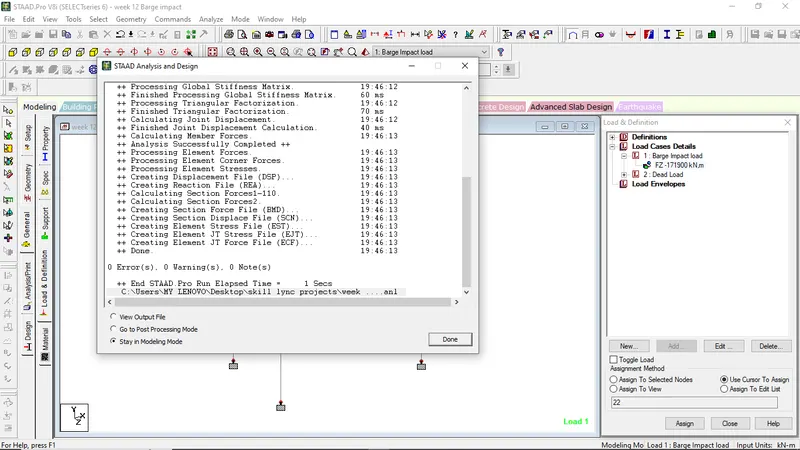
- Go to Analalysis and Print
- select No print
- Go to Analyze menu
- Click on Run Analysis
Step 6:-
Go to post processing mode to get out final analytical values
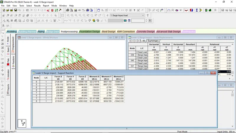
Results showing maximum support reaction for the structure on FY
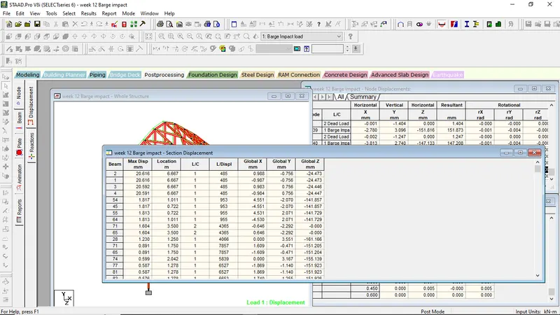
Results showing maximum displacements for the structure
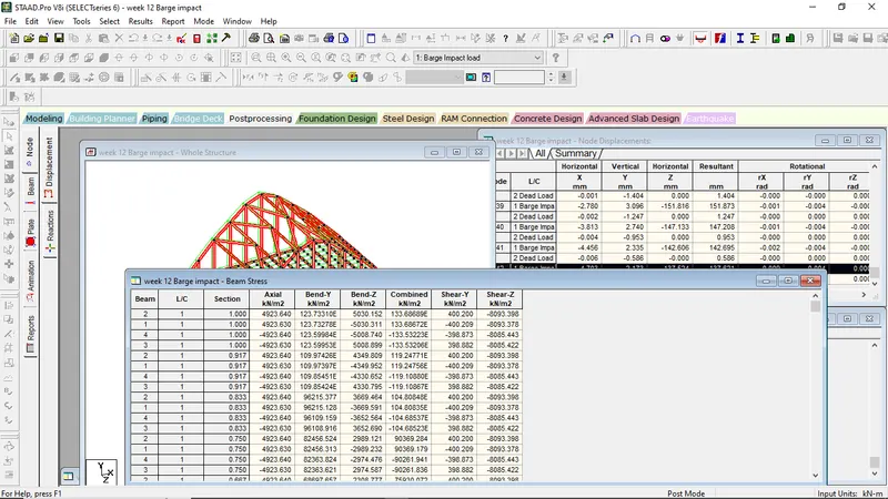
Results showing maximum beam stresses
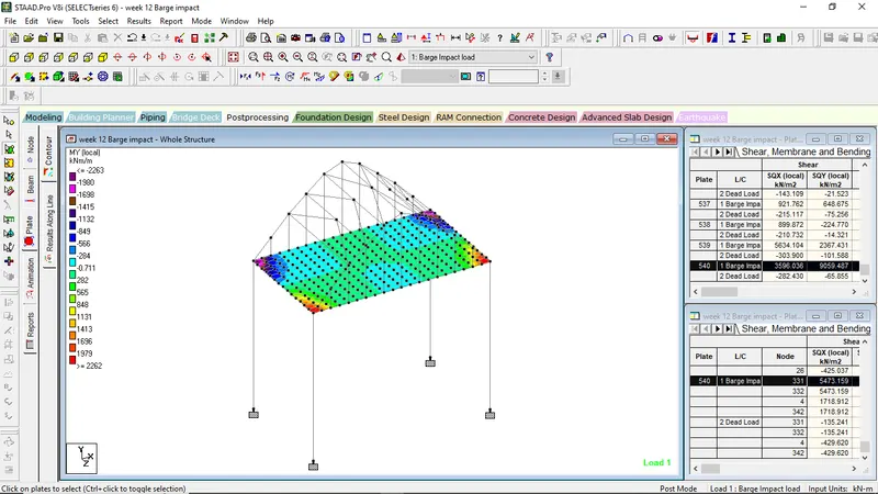
Plate contour showing maximum My values