Week 12 Challenge
Aim of The Challenge : To Model & Analyse the Bridge Section which is having span of 12m length for Barge Impact Loads acting on the bridge having Width of Deck Slab 7.0 m, The Bridge is Supported by 4 Piers having 2.5m x 2.5m rectangular size having height of 5m. The Bridge is having Truss Bridge Components the specifications of the elements can be assumed accordingly.
Introduction : As we Know Staad Pro is Designed and Maintained by Bentley Systems Software Company, Staad Pro is used for Structural Analysis and Design Purposes, As the Given Structure is a Bridge of 12m span, we have to analyse the structure for Barge Impact Loadings and briefly describe the analysis results.
Procedure :
Calculation of Barge Impact Loads:
Barge collision energy.
KE = 500 X CH X W X V2
= 500 X 1.25 X 52500 X (16.67)2
= 9118229531
Barge damage depth 'aB'.
ab = 3100 X [ (1 + 1.3 X 10⁻⁷ X KE ) x 0.5 - 1 ]
= 3100 X [ (1 + 1.3 X 10−7 X 9118229531) x 0.5 - 1]
=103675.53 mm.
Barge Collision Impact force Pb.
Pb = 6.0 X 10⁶ + 1600 X (ab)
= 6.0 X 10⁶ + 1600 X 103675.53
= 171880848 N
= 171880.848 KN.
Uniform Force.
= Pb / length of bridge
= 171880.848 / 12
= 14323.404 kN/m
Modeling :
- 1. Open Staad Pro and Create a new Project and select Metric in Unit, this will allow us to model the structure in metres as shown in the given diagram and get results in Kn.
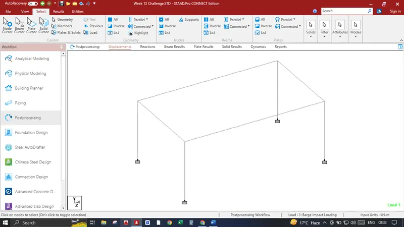
- 2. Input the origin node as 0,0,0 Select the node press CTRL C+ CTRL V input 5 in Y and press ok, create beam between two nodes, again select the beam and press CTRL C+ CTRL V input 7 in Z and press ok, again select both the beam and press CTRL C+ CTRL V input 12 in X and press ok, connect the top nodes to create main girders.
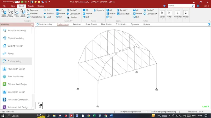
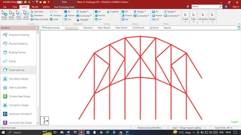
- 3. Now Create Vertical Bracings, Top Chords with Cross Girders - Select the Left Main Girder and right click select the input node command and create a node at the center. Now select the newly created center node and press CTRL C+ CTRL V input 1.5 in X and press ok, again press CTRL C+ CTRL V input -3 in X and press ok, again press CTRL C+ CTRL V input -4.5 in X and press ok, repeat this process in positive X size and this will create us nodes for our cross girders and vertical bracings, Now select the center node and press CTRL C+ CTRL V input 5 in Y and press ok join these points with the beam, again select the left and right nodes from the center and press CTRL C+ CTRL V input 4.8 in Y and press ok, again select the other 2 nodes having distance 3m from center and press CTRL C+ CTRL V input 4 in Y and press ok, again select the other 2 nodes having distance 4.5m from center and press CTRL C+ CTRL V input 3 in Y and press ok. After these beams have been created sleect the all the vertical beams from the main girders and perform Translational repeat No. of steps is 1 and distance is 7 in Z Direction and click on link steps. Also Create center nodes in top bracings and connect with the beams in zigzag manner as shown in the image below.
- 3. Now Create a Deck Slab Select the corner node of the Pier press CTRL C+ CTRL V input -0.5 in Z press ok. Select both the nodes and press CTRL C+ CTRL V input 0.5 in X press ok, create a plate inside the 4 nodes, now select the plate and perform Translational Repeat No. of steps 23, Step Spacing 0.5m in X Direction, again select all the newly created plates perform Translational Repeat No. of steps 13, Step Spacing 0.5 m in Z Direction. which creates our deck slab of 7m wide and 12m long.
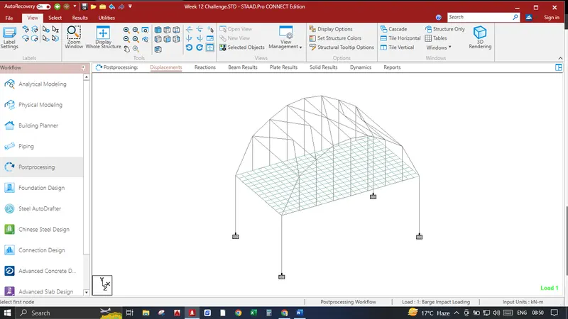
- 4. Now we have to Provide Supports in Pier Bottom Select all the bottom Nodes Click on Specification in Upper Tab Create a Fixed Support and Assign the Bottom Nodes to Fixed end Support. After all the steps the Model will look like this.
Assingning Specifications :
Creating Groups :
- 1. Click on Utilities and Click on Groups, again click on Create enter name as MAINGIRDERS and type Beam new group has been created, click on select click on Parallel under Beams click on parallel to X which selects both the Longitudinal Girders Click on associate to selected Geometry. again click on Create enter name as CROSSGIRDERS and type Beam new group has been created, click on select click on Parallel under Beams click on parallel to Z which selects all the Cross Girders Click on associate to selected Geometry. again click on Create enter name as PIERS and type Beam new group has been created, click on select click on Parallel under Beams click on parallel to Y which selects All the Piers Click on associate to selected Geometry. again click on Create enter name as DECKSLAB and type Plate new group has been created, Select all the plates Click on associate to selected Geometry.
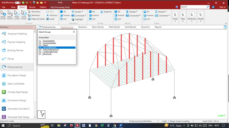
- 2. Now Group the Vertical Bracings and Top Chord Members, again click on Create enter name as TRUSSVERTICAL and type Beam new group has been created, Select the Vertical Trusses as shown in the image Click on associate to selected Geometry.
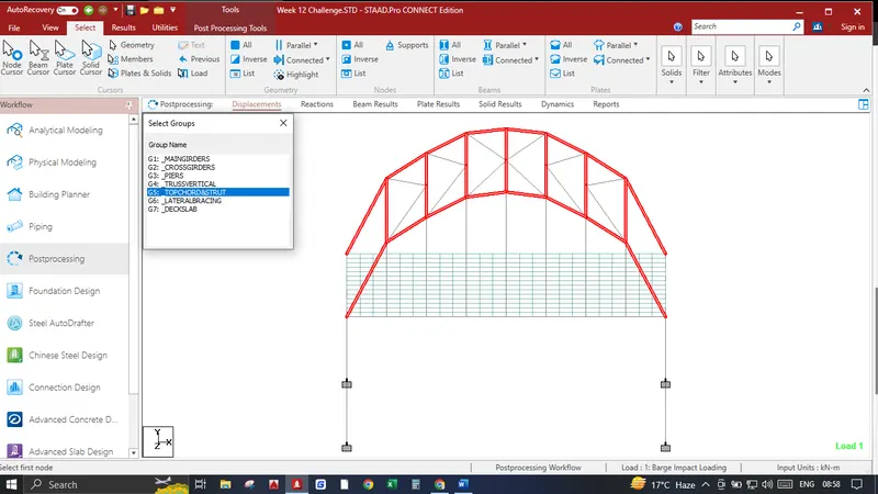
- 3. Again click on Create enter name as TOPCHORD&STRUT and type Beam new group has been created, Select the Components as shown in the image Click on associate to selected Geometry.
- 4. Again click on Create enter name as LATERALBRACINGS and type Beam new group has been created, Select the Components as shown in the image Click on associate to selected GeometrY
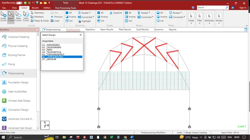
Hence all the Groups has been Created it is lot easier for us to assign specifications for certain objects.
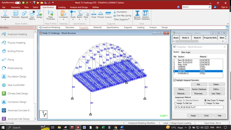
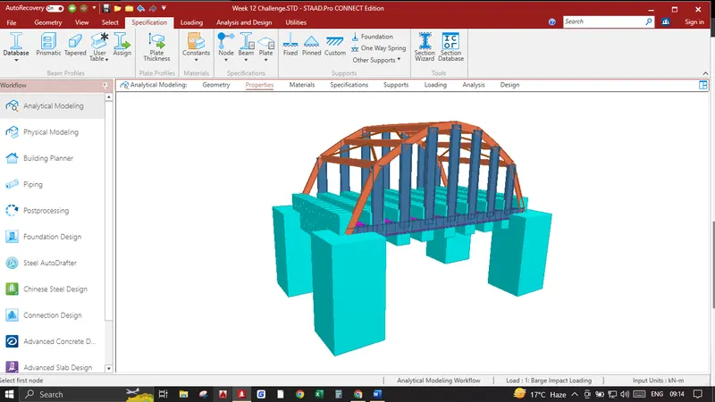
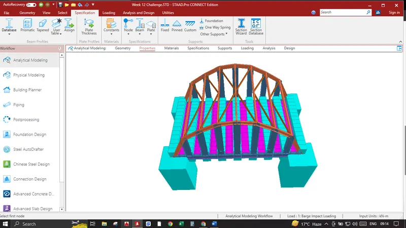
- Click on Specification Tab click on Define click on Rectangle and input YD-2.5 and ZD-2.5 this will create a specification for piers select the piers from groups and assign. Again click on Define click on Rectangle and input YD-1.8 and ZD-0.75 this will create a specification for Cross Girders select the Cross Girders from groups and assign. Again Click on Thickness and add a plate of 0.5 m click ok this will create specification for Deck Slab select the deck slab from groups and assign.
- Now Select the Section Database and add ISMB 600 Steel and assign it to main girder group, again add ISMB 550 Steel and assign it to Vertical truss group, again add ISMC 350 Steel and assign it to TOPCHORD&STRUT group. again add ISA 90x90x12 Steel and assign it to LATERALBRACINGS group.
Adding Barge Impact Load:
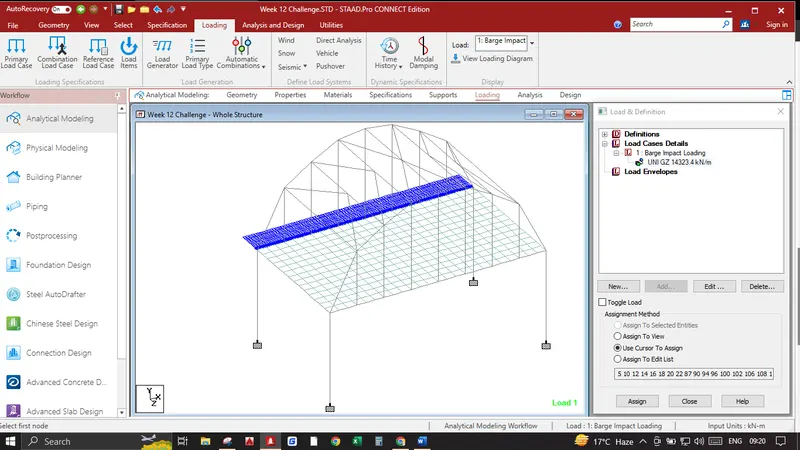
- 1. Click on Load Cases Details Click add write name Barge Impact Loading click add again click add select Member Load , under member load select uniform force and input the values mentioned in the image below.click add
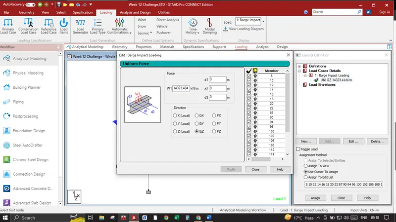
- Select the Left Main Girder and assign it to the selected geometry.
Analysis & Results :
- 1. Click on analysis and design click on define commands click add which adds a command for perform analysis, press run analysis, again go to post processing
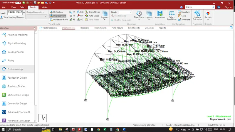
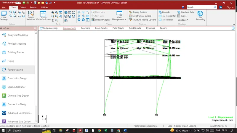
In Results Tab Displacement Pattern show in the image below
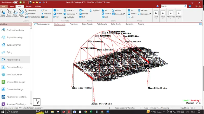
In Results Bending Moments shown in the image below
In Results Shear Stresses are shown in the image below
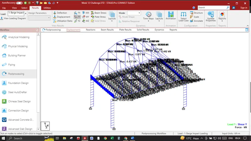
In Results Plate Stresses in MX Local are shown in the image below
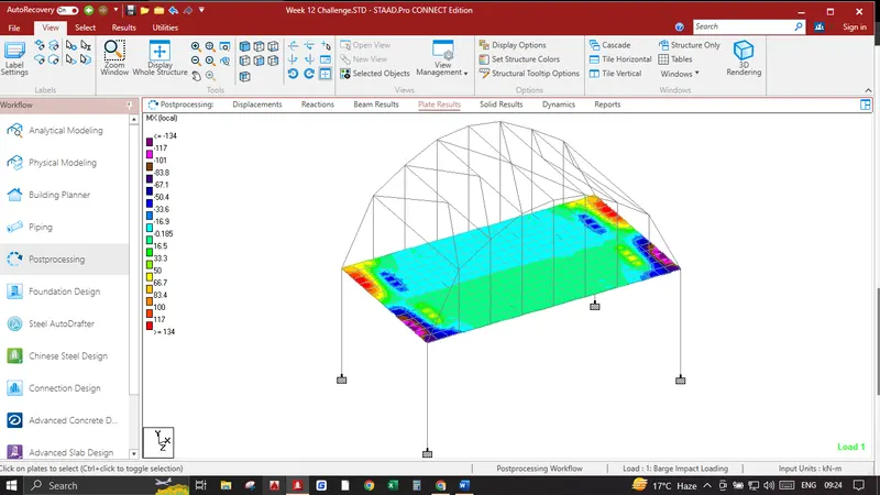
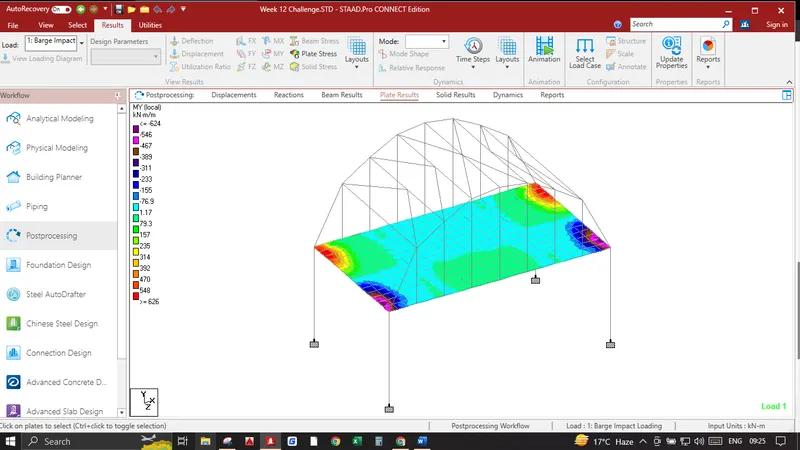
In Results Plate Stresses in MY Local are shown in the image below