Week 12 Challenge
Intrduction:-
Barage impact load , As per IRC Code 6 -2017,Clause 219
Bridge components located in a navigable channel of rivers and canals shall be
designed for barge impact force due to the possibility of barge accidentally colliding
with the structure.
For bridges located in sea, and in waterways under control of ports, the bridge
components may have to be designed for vessel collision force, for which the details
of the ships/barges shall be obtained from the concerned authority. Specialist
literature may be referred for the magnitudes of design forces and appropriate
design solutions.
The design objective for bridges is to minimize the risk of the structural failure of a
bridge component due to collision with a plying barge in a cost-effective manner and
at the same time reduce the risk of damage to the barge and resulting environmental
pollution.
AIM :-
Here we calculate Barge impact load on given bridge with the help of staad pro as per given data.
Procedure :-
For barge impact on bridge here some data are given as,
I. Dead weight -52500 DWT
II.No of container -4500
III.Weight of one container -6.1 TEU
IV.Speed of Barge -60km/h
V.Length of vessel -294m
VI.Span of bridge -12m
VII.Width of bridge -7m
VIII.Pier size -2.5mX2.5m
IX.Rise of bridge -5m
X.Type of bridge -Steel Bridge
XI.Thickness of slab -0.500m
XII.Cross girder size -0.75mX1.8m
XIII.Hydronamic cofficient(CH) -1.25
Now calculate Load due to brage impact with the help of IRC-6,
Barge Collision Energy-
KE=500 X CH X W X V2
where,
W = Barge Displacement Tonnage (T)
V = Barge impact speed (m/s)
KE = Barge Collision Energy (N-m)
CH = Hydrodynamic coefficient
= 1.05 to 1.25 for Barges depending upon the under keel clearance available.
● In case underkeel clearance is more than 0.5 x Draft, CH=1.05;
● In case underkeel clearance is less than 0.1 x Draft, CH = 1.25.
● For any intermediate values of underkeel clearance, linear interpolation
shall be done.
Put the values as given,
KE=500 X1.25X52500X(60X1000/(60X60))^2
=9,11.495X10^7 n-m
Now,
Barge Damage Depth, ‘aB’
aB= 3100 x ( [1 + 1.3 x 10(-7) x KE]0.5 - 1),
where,
aB = Barge blow damage depth (mm)
=3100X ([1+1.3X10^-7X911.495X10^7]0.5-1)
=1,03,656.344 mm
Barge Collision Impact Force, ‘PB’
The barge collision impact force shall be determined based on the following equations:
For aB<100 mm, PB = 6.0 x 10⁴x (aB), in N
For aB ≥ 100 mm, PB = 6.0 x 10⁶+ 1600 x (aB), in N
Here value of aB is more than 100mm so
PB=6X10⁶+1600X (103656.344)
=1.658x10^8 N
=1.658x10^5 Kn
Uniform force at bridge slab is ,
PB/Length of bridge
=1.658X10^5/12
=13821 Kn/M
=13821N/MM,
Now we create the model with the help of staad pro and apply the calculated load on model and get the results .
for staad pro we follow the given steps ,
as
1. Open the staad pro and start as new model which load is barage load and get the new window such as

2.Start the modeling from pier node as showing .
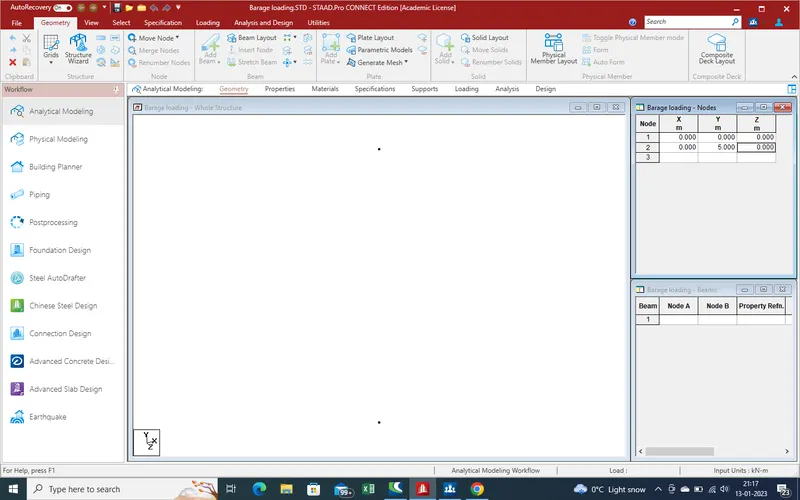
3.Use of translation repeat command we get the remainig pier get.
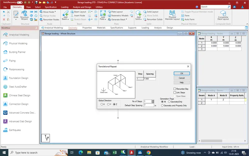
4.
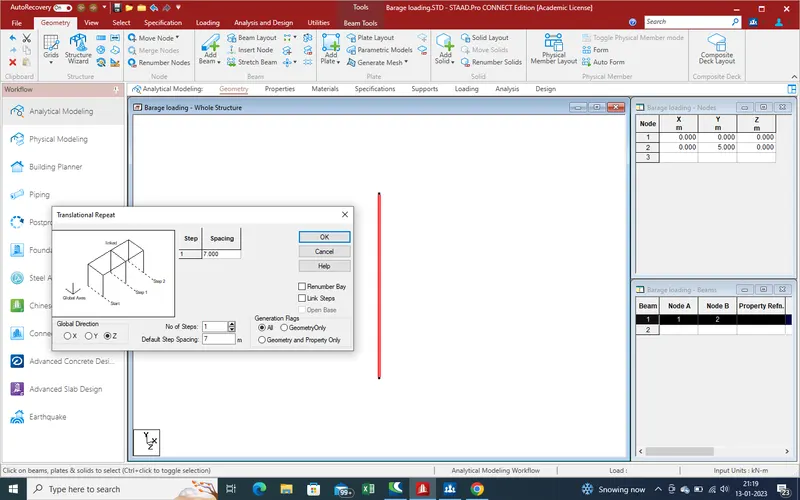
5.
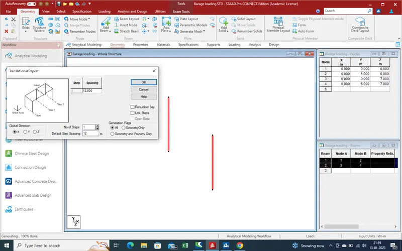
6.With the help of beam command the create the main and cross girder as showing .
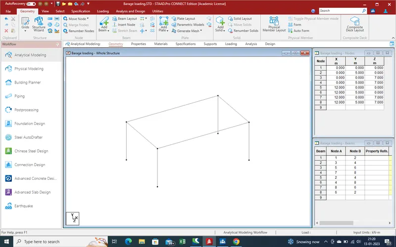
7.With the trainslation command create nodes for arch
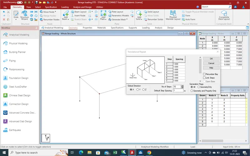
8. And get the results as below showing
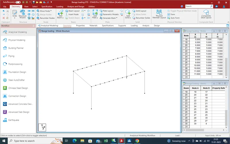
9.Now select the node and with the help of translation repeat command get the second node at specifiy height in y- direction .
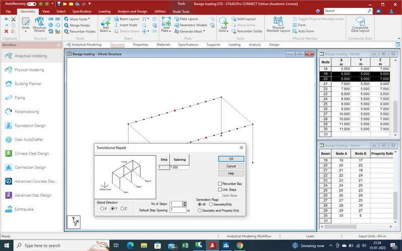
10.As we get the arch node as showing
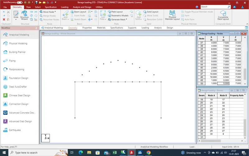
11.
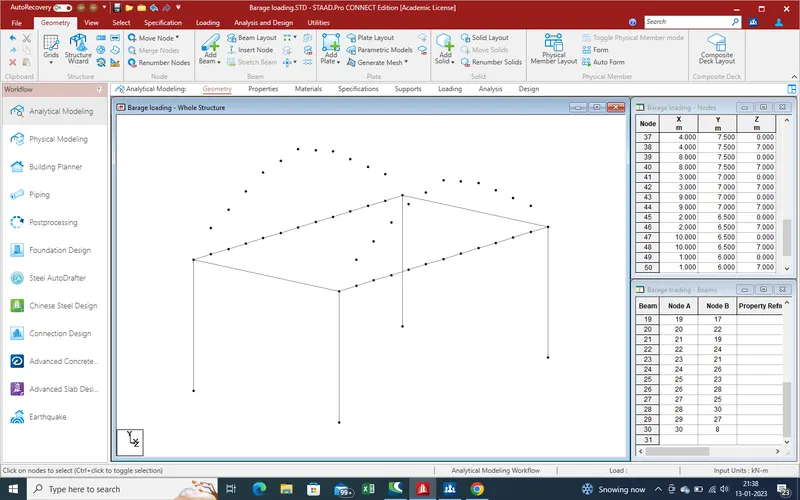
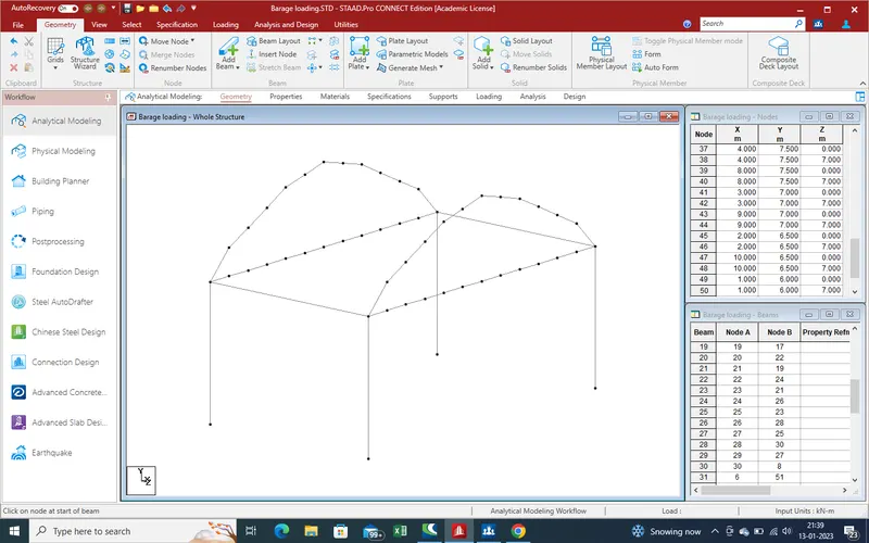
12.Connect the nodes with the help of Beam command for arch
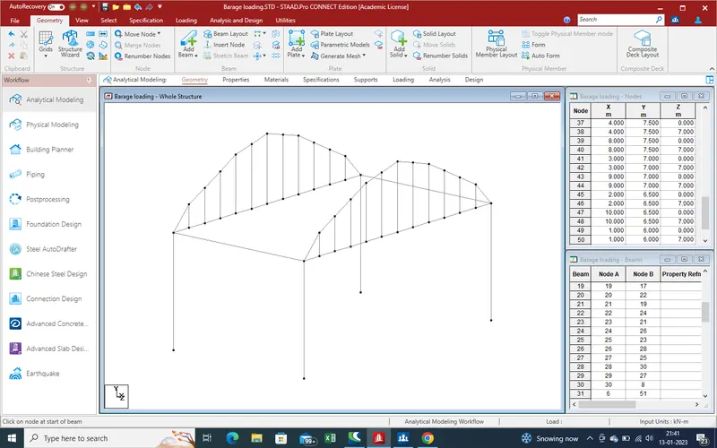
13.Also connect the vertical nodes for vertical connection .
14.
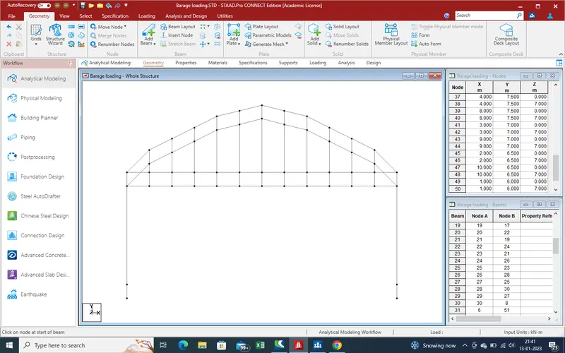
15.Also connect the arch horizontal .
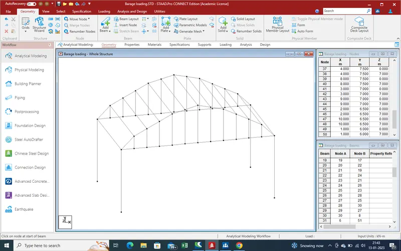
16.
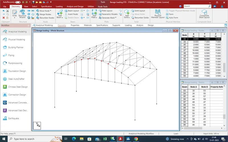
17.With the help of new view open the slab section for create the plate section at slab section .
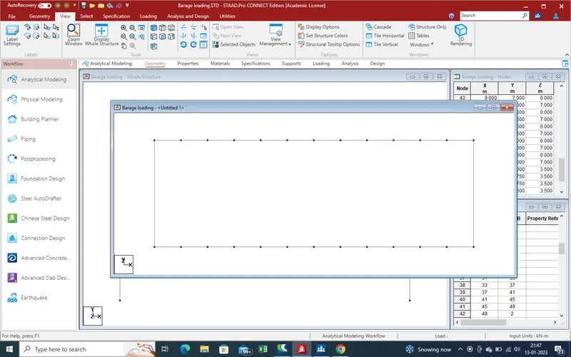
18.Create the cross girder beam with the help of translation repeat command .
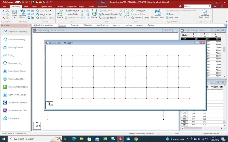
19.Now add new node for create plate nodes for slab with the help of translation repeat command.
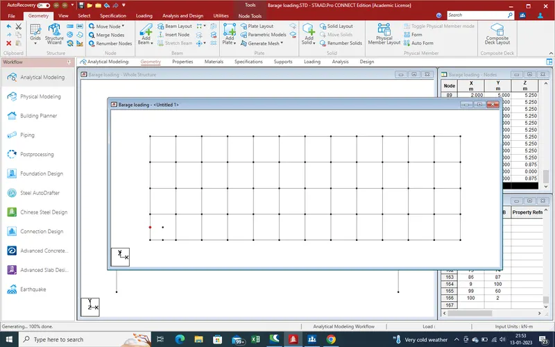
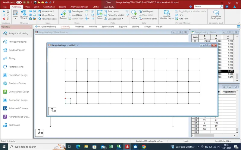
20. Now create the plate section with the help of new 4 nodes
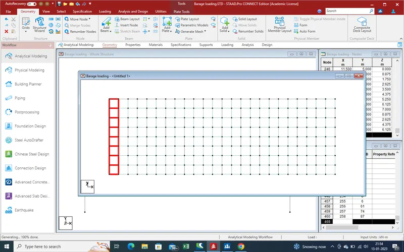
20. With the help of translation repeat command we get the plates section over whole slab section as showing in given pic .
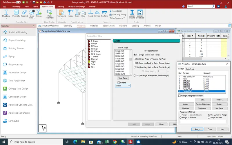
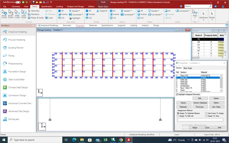
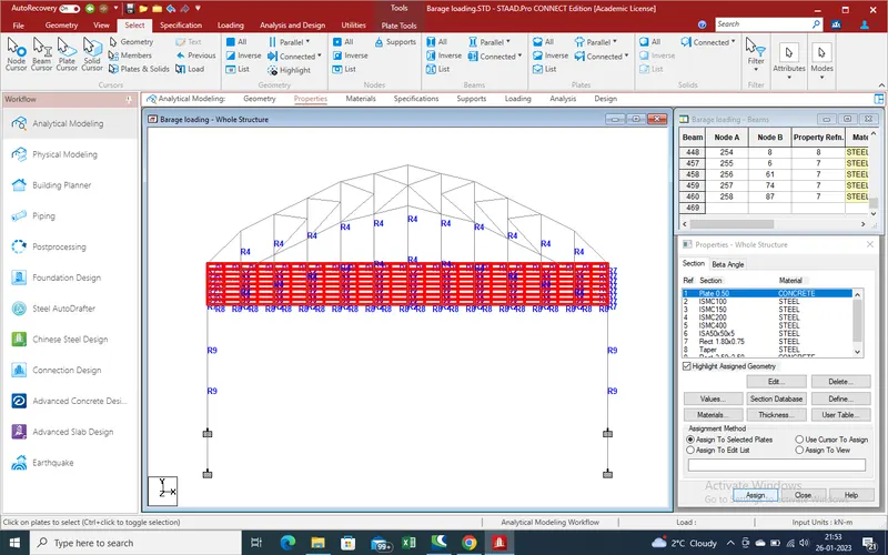
21.Now define the properties for assume different section as shown in given pic as below.
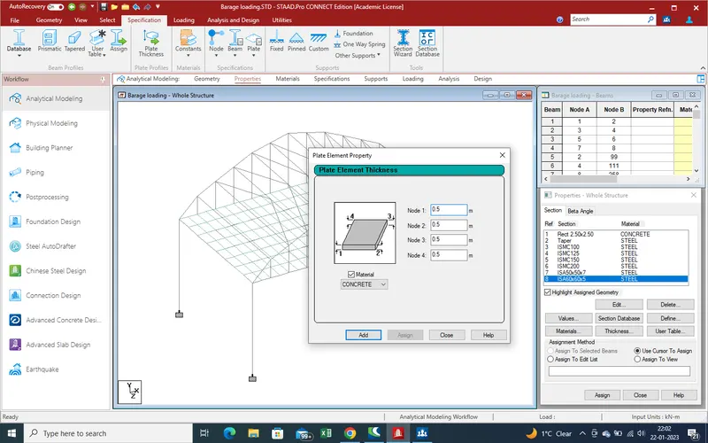
22. As given that the slab thickness given as 500mm thick .
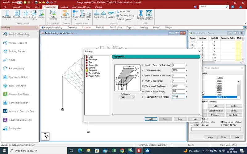
23. Main girder diamension as such as .
24.Apply the properties of pier as shown
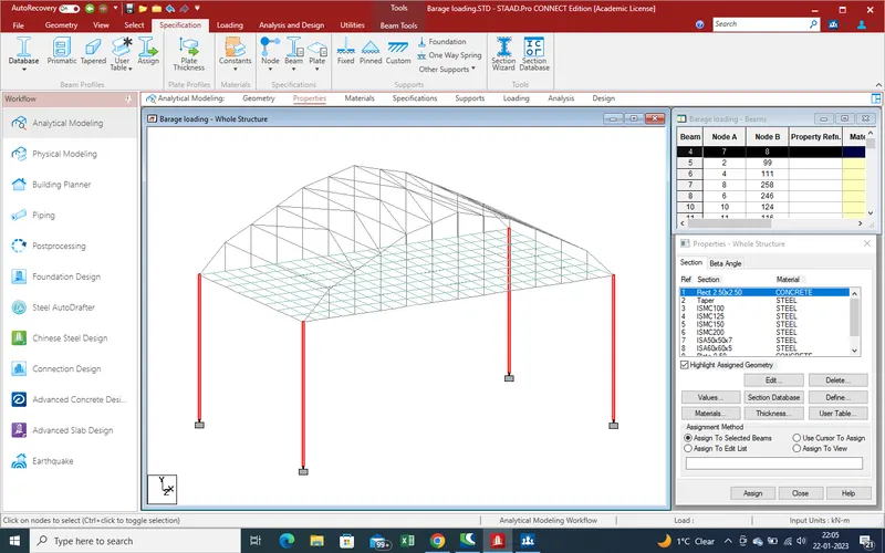
properties for main steel girder .
properties of pier as 2.5m X2.5m rec.
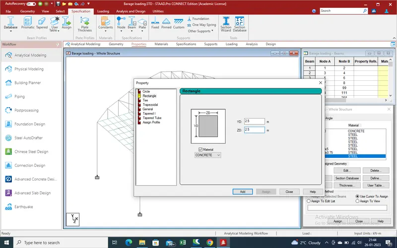
Assign of properties of pier
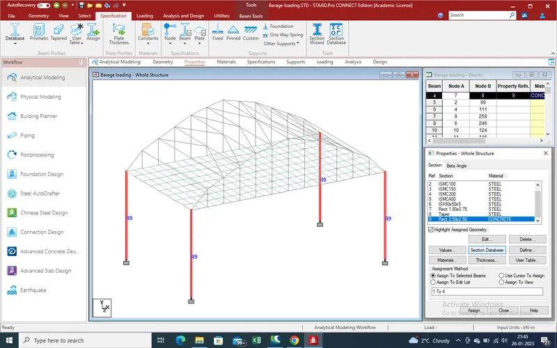
vertical main beam for conect the slab to arch
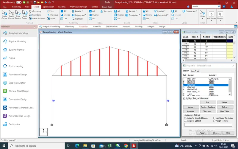
main girder of slab .
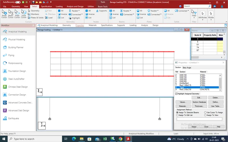
cross girder
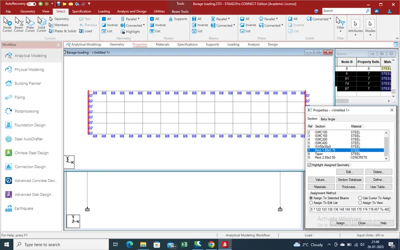
intermediate main girder
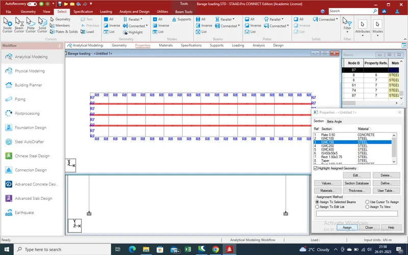
Properties for cross girder of slab .
Properties for plates section of slab .
Arch main beam
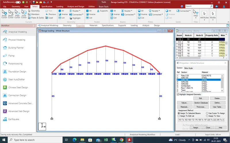
Arch main beam for assign properties .
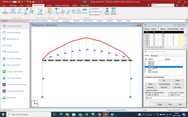
Assign the properties for connection of main both arch .
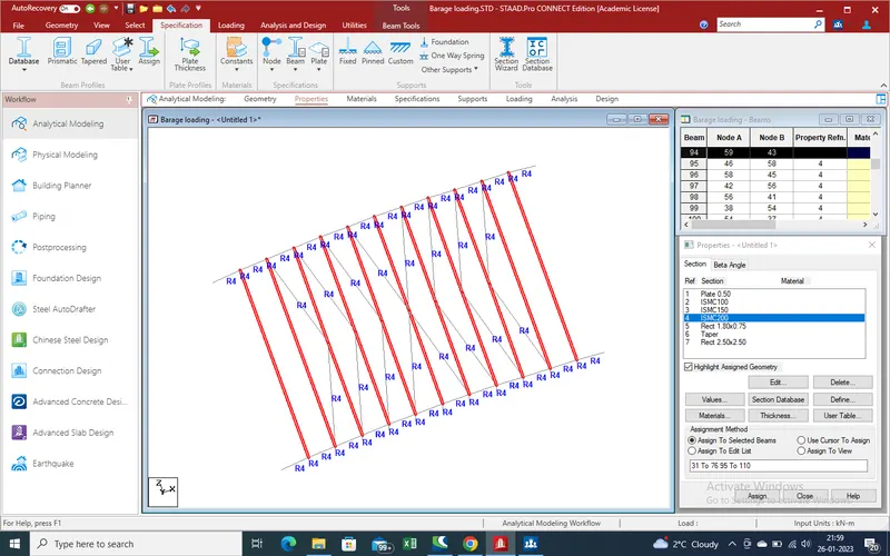
Selection of cross of top of arch .
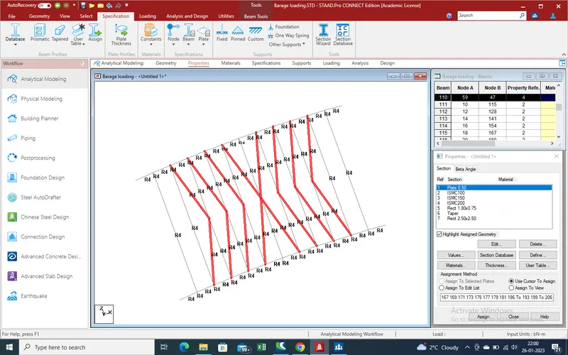
25. Select the node of pier bottom for apply support .
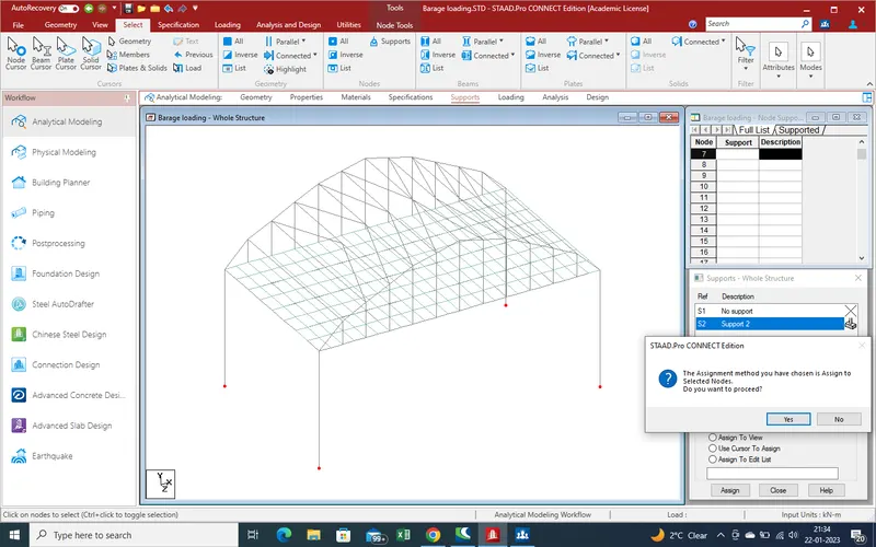
26. Apply the support reaction as fixed support .
27.Now define load due to barrage load on bridge .
Go to load case details for define new load case
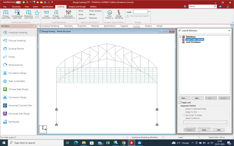
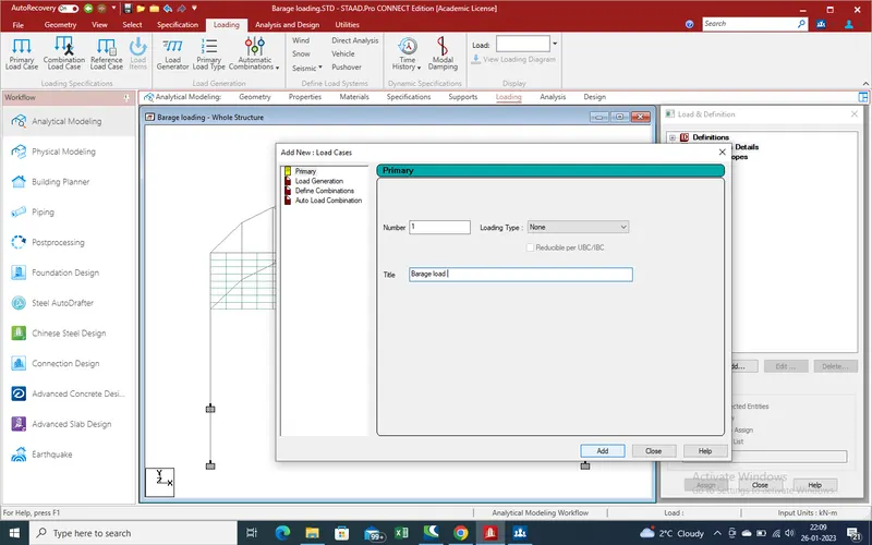
28.Add new slection a new window open as showing and primary load is barage load and add and close the window .
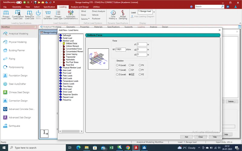
29.As barage load act on bridge as uniform member load in Z-direction ,So select the member load in uniform load .
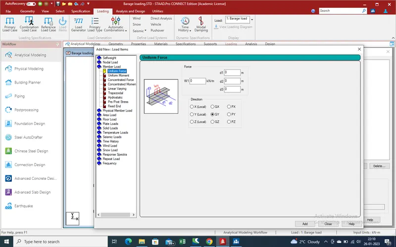
30.As above we calculate the load which is 13821 kn/m will apply as w1 load in Z-direction add and close the window .
31.Now select the main girder of outer side for assign the load and apply .
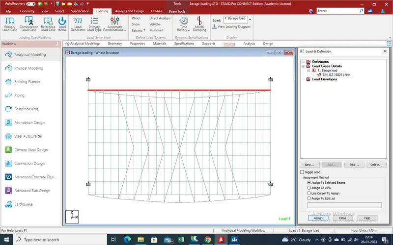
32.Selection of beam where we apply the load .
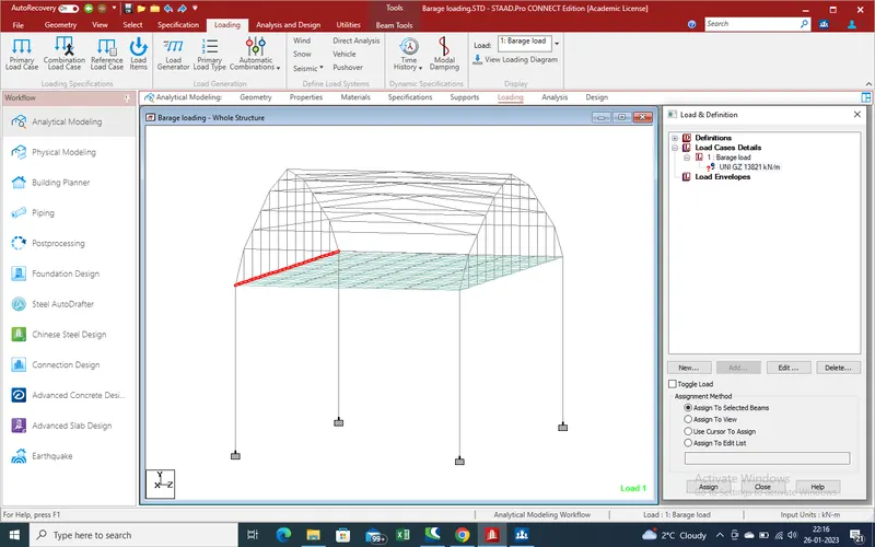
33.View of load on bride.
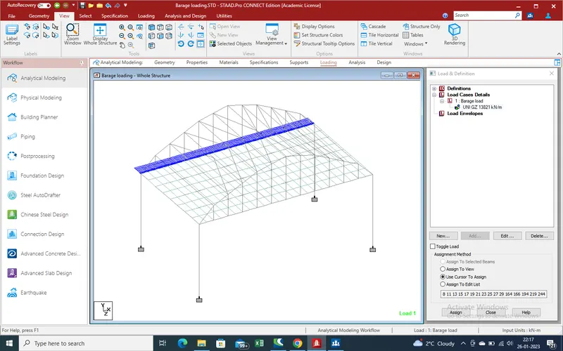
34.Now run the analysis and get the zero error so go for post processing for get the results
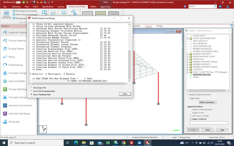
Results :-
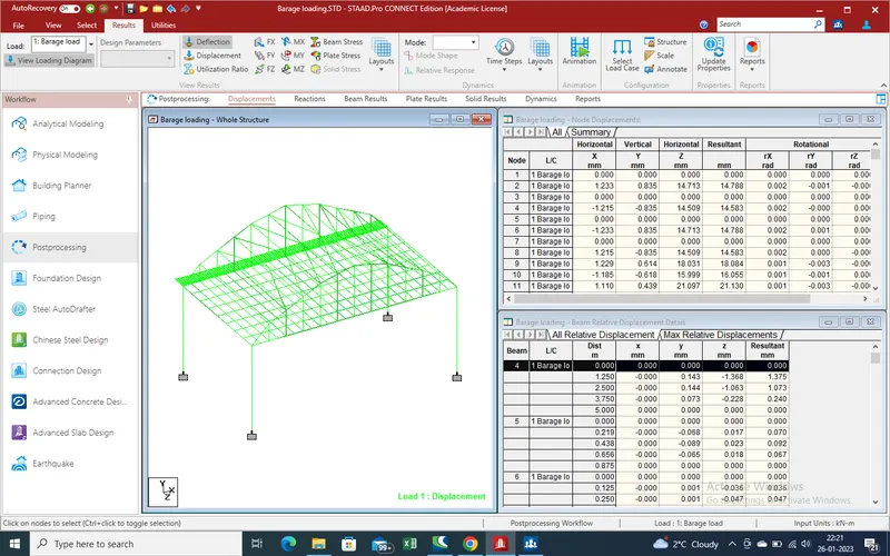
Now we get the results due to barage load on bridge .
1.Deflection due to barage load .
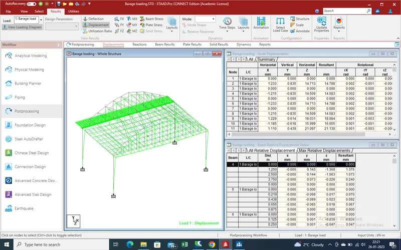
2.Displacement in bridge due to barage load .
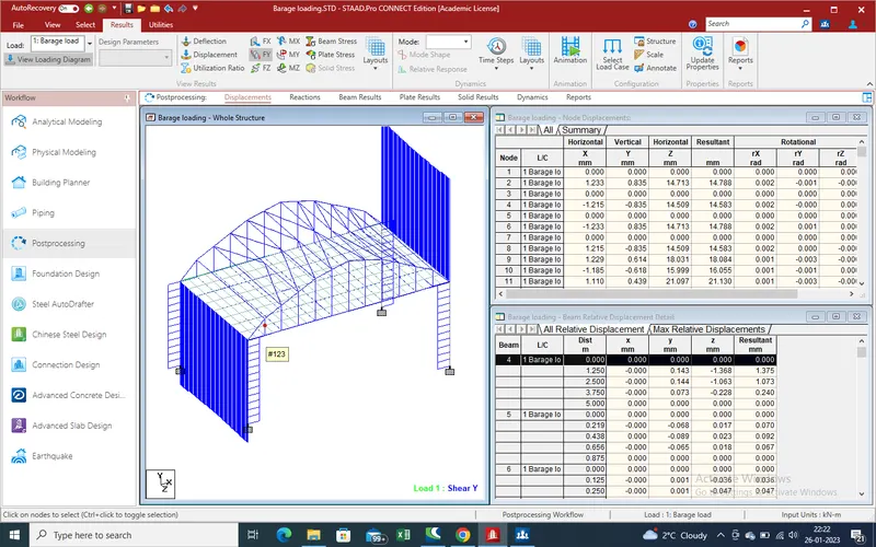
3.Displacement due to force act as shear force .
4.Displacement due to load act as shear force in z-direction .
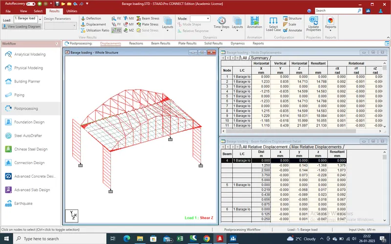
5.Displacement due to moment in X-direction by barage load .
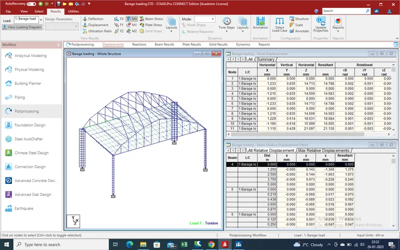
6.Displacement due to moment in y-direction .
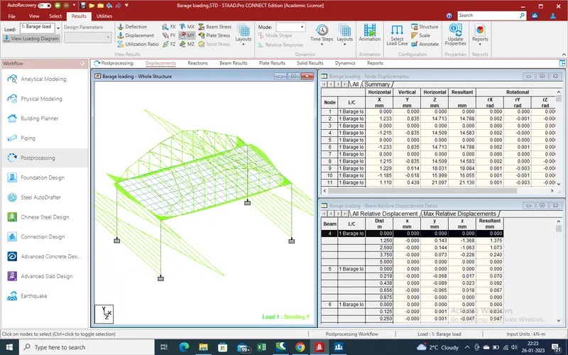
7.Moment displacement in Z-direction due to barage load .
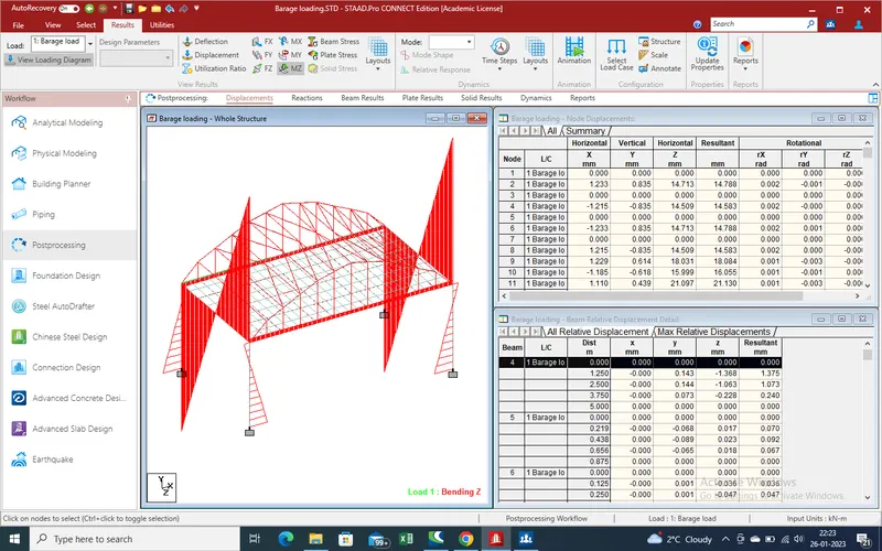
8.Beam stresses.
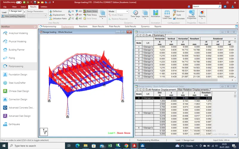
9.Plates stresses in Max absolute load
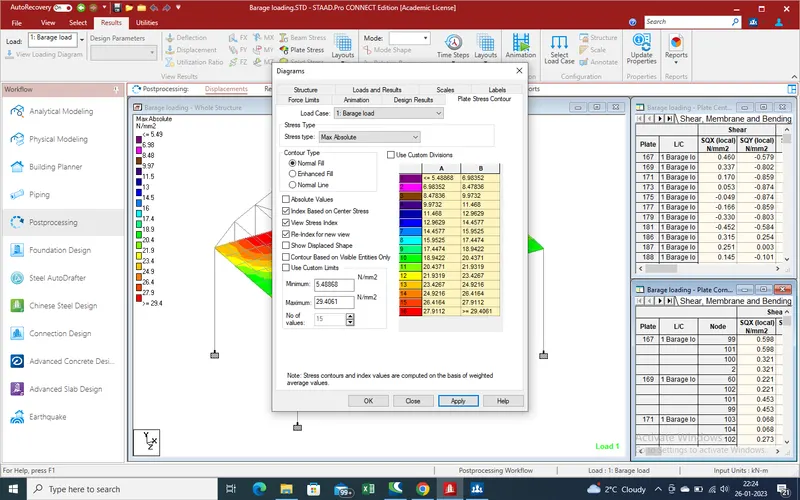
10.
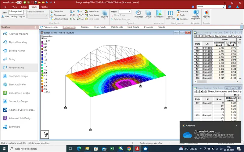
11.
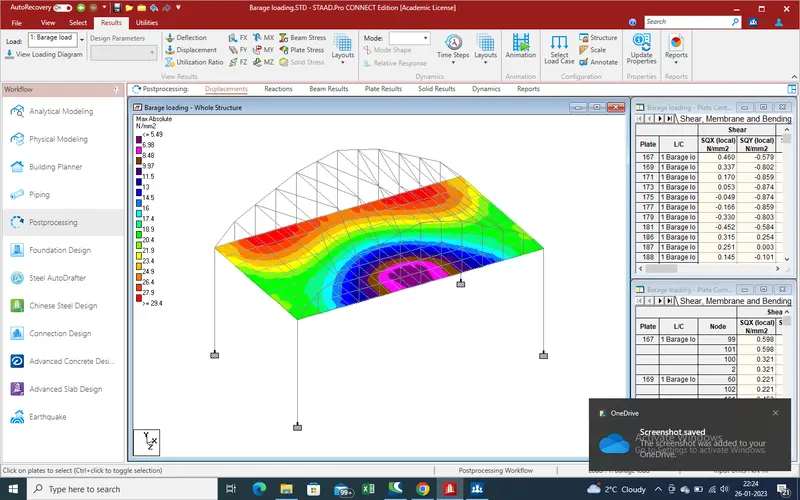
12.Support reaction
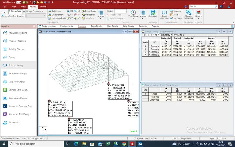
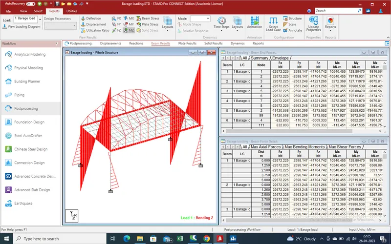
13. Beam results due to moment in z-direction .
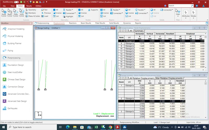
14.Dispacement in pier .
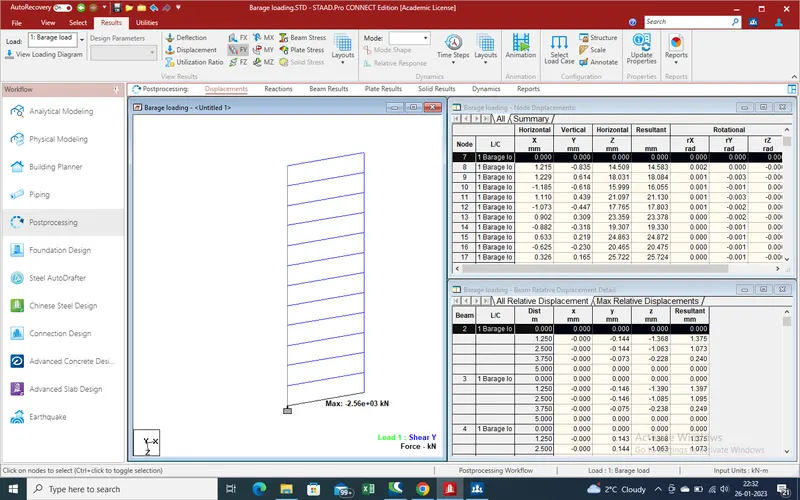
 15.Dispalcement due to shear force in y-direction .
so we get the all effects due to barage load on a bridge. Here also attached the report copy and staad copy also for referance .