Week 12 Challenge
Aim : To calculate the barge impact load of the panamax vessel on the bridge.
Given data :
- Dead weight tonnage of panamax vessel is 52000 DWT.
- Speed of the barge is 60 km/hour
- Span of bridge is 12 m
- Width of bridge is 7 m
- The pier of size is 2.5 x 2.5 m
- The cross girder size is 0.75 x 1.8 m
- Thickness of deck slab is 500 mm
Theory :
Barge impact is a potential hazard for bridge piers located in navigation waterways. The dynamic impact process is influenced by many factors, including barge mass, impact velocity, oblique impact angle, water elevation, material properties of pier members, soil properties.
Calculation :
Hydrodynamic coefficient 1.25
KE = 500 x CH x W x V2
= 500 x 1.25 x 52500 x 16.622
KE = 906.36 x 10⁷
ɑβ = 3100 x [ 1 + ( 1.3 x 10-7 x 906.3 x 107]0.5 -1)
ɑβ = 106406.79
Pβ = 6 x 10⁶ + ( 1600 + 106406.79)
Pβ = 7.34 x 10¹⁰ N
Aim : To prepare the model in a STAAD Pro and perform the analysis and justify with the results.
Theory : The general steps to be create a STAAD Pro model is given below,
Step 1 : Create the nodes by using the nodes cursor.
Step 2 : Joining the nodes by using the respective beam plate cursor.
Step 3 : Supports given to the nodes whether its pinned or fixed or any other custom supports
Step 4 : specifications given to the respective beams plates
Step 5 : Assign the dead load as per calculation
Step 6 : Save the model and perform the analysis
Step 7 : The results are obtained and discuss with the results
Step 8: Take the print out of report of necessary results.
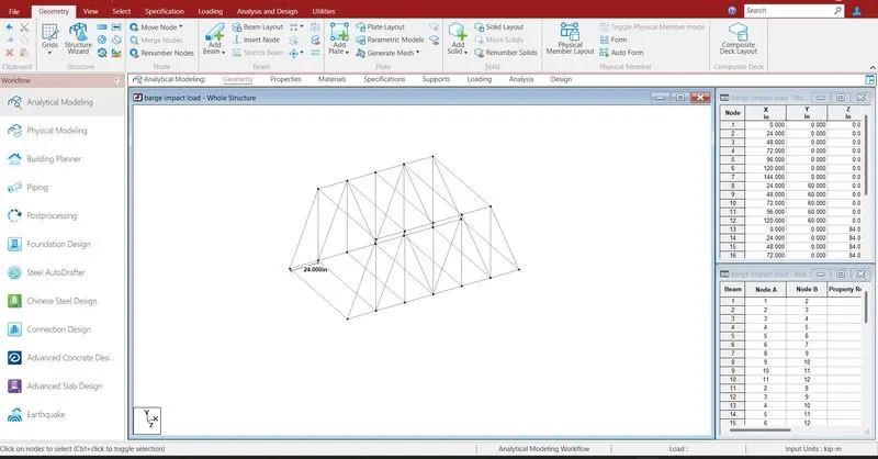
Creating the nodes by using node cursor.
Open the STAAD Pro window > Select > Node cursor > enter the value with respect to X Y Z axis > click enter.
By using structure wizard truss model has been transferred to the staad window with suitable given data.
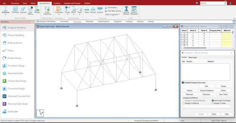
To draw additional beams which is to be drawn apart from truss model has been modeled by using below method.
Join the nodes by using beam cursor.
Select > beam cursor > join by dragging the mouse or enter the node numbers > click enter
Supports are given to the respective nodes.
Specifications > Supports > select the supports > click enter
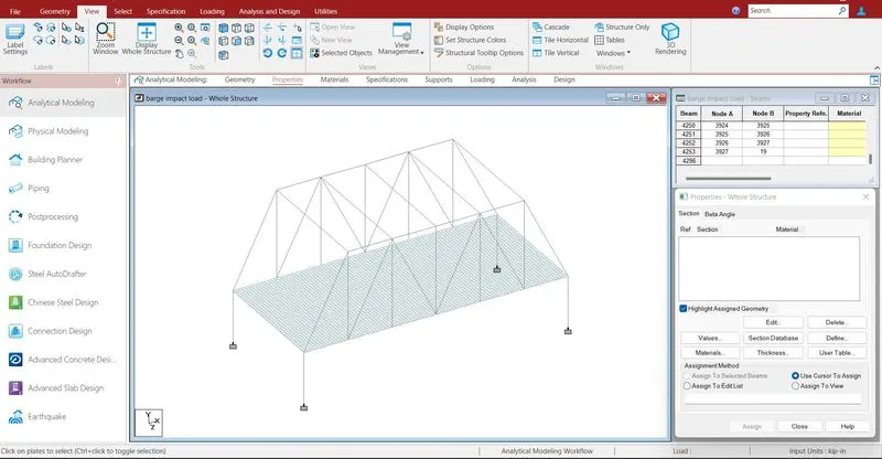
Mesh like structures has been drawn to create a deck slab.
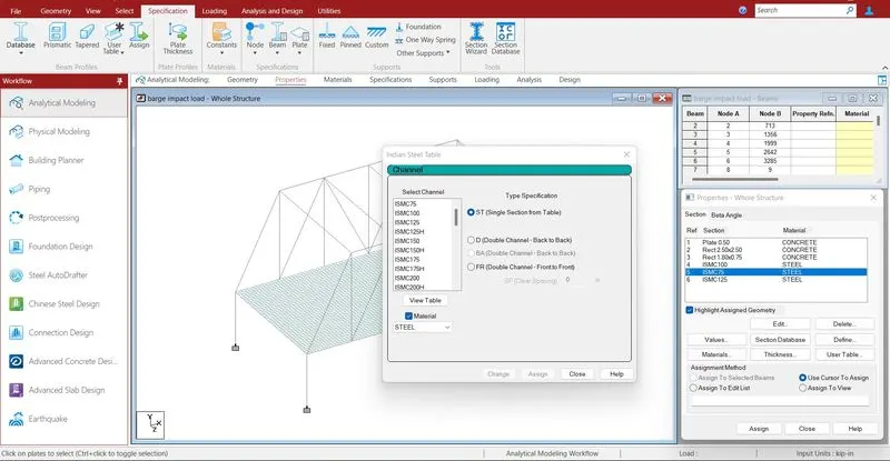
Specification > Prismatic > Rectangle > enter dimensions > select the beam > assign the properties to selected beams.
All the concrete structures and steel section data base has been defined.
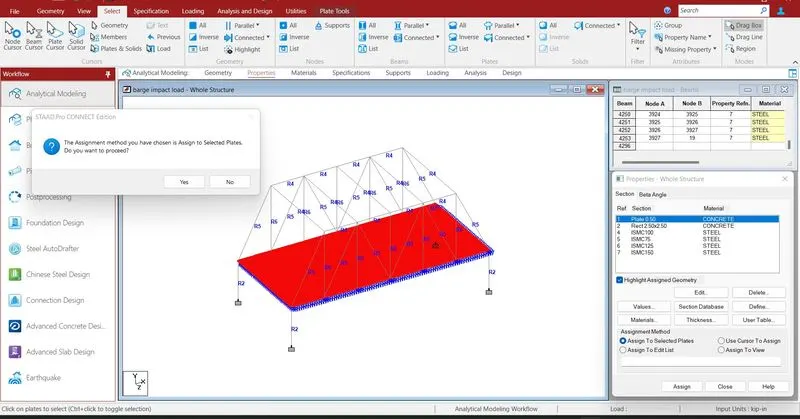
All properties are assigned with respective structures deck slab, beam, piers.
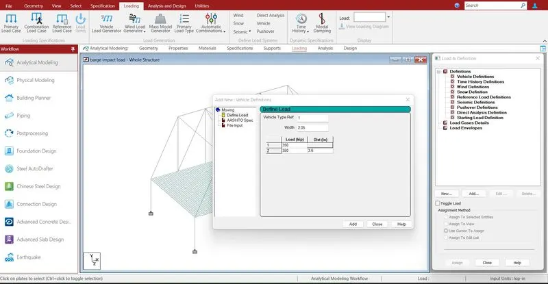
Defining the load cases .
Loading > definition > vehicular load > define type of vehicle > add
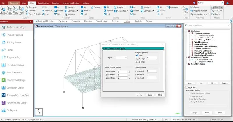
Loading > Load case detail > load generation > Add
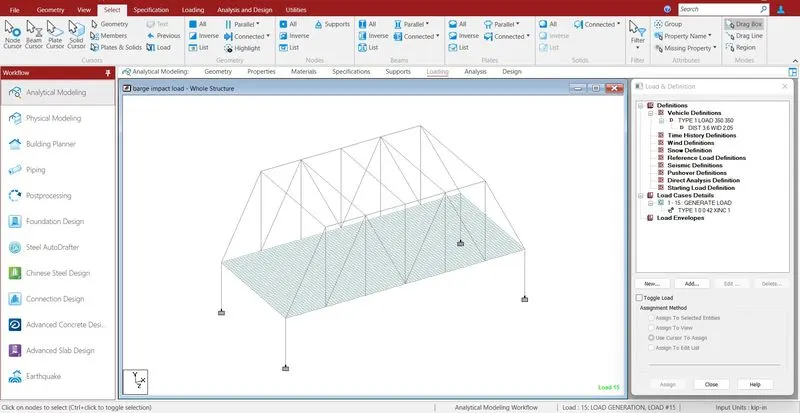
click add > enter the ranges to be load assigned > ok
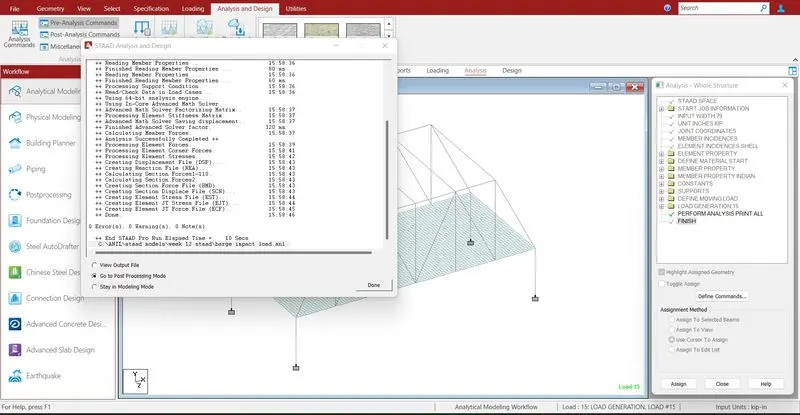
Run analysis > go to post processing mode > Results
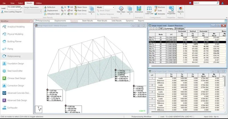
The reactions are generated at the end of the nodes .the reaction value is 709.980 KN
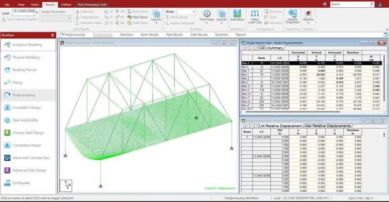
- The maximum deflection in X direction is 0.179 mm
- The minimum deflection in X direction is -0.246 mm
- The maximum deflection in Y direction is 0 mm
- The minimum deflection in Y direction is -29.956 mm
- The maximum deflection in Z direction is 0.140 mm
- The minimum deflection in Z direction is -0.014 mm
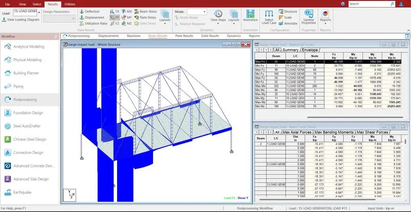
- The maximum shear force in X direction is 709.98 KN
- The minimum shear force in X direction is -274.543 KN
- The maximum shear force in Y direction is 669.523 KN
- The minimum shear force in Y direction is -642.019 KN
- The maximum shear force in Z direction is 46.135 KN
- The minimum shear force in Z direction is -46.199 KN
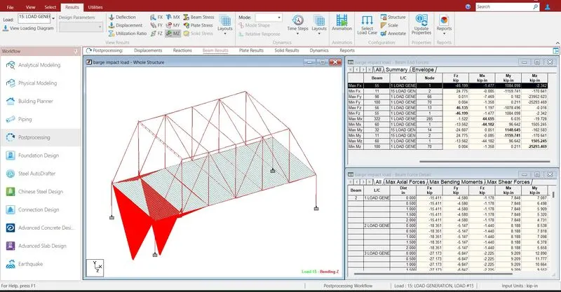
- The maximum bending moment in X direction is 44.655 KN-m
- The minimum bending moment in X direction is -44.182 KN-m
- The maximum bending moment in Y direction is 1148.645 KN-m
- The minimum bending moment in Y direction is -1159.741 KN-m
- The maximum bending moment in Z direction is 1505.245 KN-m
- The minimum bending moment in Z direction is -25293.469 KN-m
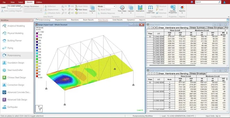
- The maximum shear stress in X direction is 591 KN/m2
- The minimum shear stress in X direction is -1362 KN/m2
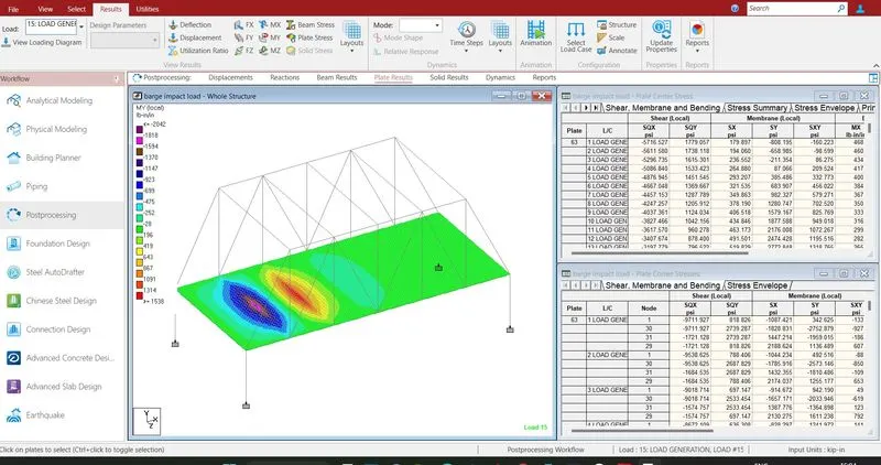
- The maximum shear stress in X direction is 1538 KN/m2
- The minimum shear stress in X direction is -2042 KN/m2
- Reports are taken printout which ever is necessary by using report
- In the report option we obtain the results of section forces, displacement, reactions, plate
- The exact report is to be taken further move to design