Week 11 - Simulation of Flow through a pipe in OpenFoam
simulation flow through a pipr from open foam
objective:
- the main objective of the project is to simulate the flow through the pipe in OPEN FOAM software.
- we have to write the program fro the generation of the blockmeshdict file, or computational mesh for wedge angle and grading scheme.
- calculate the length of the pipe using the entry length formula through the laminar flow through the pipe.
- show that the entry length is enough for producing the fully developed flow.
- and we have to compare the velocity profile at the different lengths of the pipe.
- we have to show our velocity profile is fully developed.
- post-process velocity and shear stress.
ASSUMPTIONS
- flow is steady, incompressible, and laminar.
- flow is two dimensional.
- fluid properties are constant(viscosity ,density ,etc..)
introduction to laminar flow through a pipe:
In this project, we aim to simulate a section of pipe (Wedge shaped geometry) to understand various aspects of flow through the pipe. The fluid chosen is water & the flow is laminar & incompressible. Also, we choose to neglect any changes in cross-section. The specified Reynold's number Re is 2100.
Internal flow occurs when the fluid is filled entirely in a conduit & is driven primarily by a pressure difference.
Fluid velocity in a pipe changes from zero at the surface because of the no-slip boundary condition to a maximum at the pipe center. The average velocity remains constant in an incompressible flow when the cross-section of the pipe is constant.
Reynold's Number (Re):
The transition from laminar flow to turbulent flow occurs from laminar (Re≤">≤≤2100) to Transition (2100≤">≤≤Re≤">≤≤4000) to turbulent (Re ≥">≥≥4000) for smooth pipe with no viscous dissipation. It depends on the geometry, face roughness, flow velocity, surface temperature, etc. Reynold's number is an important non- Dimensionless number which is the ratio of the inertial force to viscous force and is expressed for internal flow in a circular section pipe as,
Hydrodynamic Length (Le) :
The region from the pipe inlet to the point at which the velocity boundary layer merges at the centreline is called the hydrodynamic entrance region in which the velocity profile is fully developed is called the fully developed region.
In laminar flow, the entry length is given approximately as,
DIAMETER OF PIPE:
we can assume the diameter of the pipe i.e
diameter = 10mm = 0.001 meter.
to calculate the hydrodynamic entry length we have a formula,
and the Reynolds number for the laminar flow is 2100. i.e Re= 2100
`L_e = 0.06*R_e*D`
`L_e = 0.06*2100*0.001`
Le= 12.6 meters
so we can take the nearer value of length that is equal to = 15
TO CALCULATE THE VELOCITY OF THE FLUID THAT IS AVERAGE VELOCITY.
AT THE INLET OF THE PIPE.
`R_e = (V*D)/v`
where v is the viscosity of the fluid i.e = `8.9 *10^-7`
Re is the Reynolds number, for laminar flow = 2100
D is the density of the liquid at 25-degree Celcius = 0.01
so by this equation, we can calculate the velocity of the moving fluid inside the pipe
`V_(avg) = (2100* 8.9*10^-7)/0.01`
WHICH GIVES TYHE RESULT OF V = 0.1869`m/s`
according to haigen poisulles equation
the pressure drop
`DeltaP = (32 *mu*LV)/D^2`
`DeltaP = (32 *8.4*10^-4*1.5*0.1869)/0.01^2`
`DeltaP = 79.84 p`
`Delta P = 0.0789 m^2/s^`
to calculate the maximunm velocity we have formula
`V_(max) = 2 *V_(avg)`
`V_(max) = 0.3738 m/s`
PROGRAMME TO GENERATE THE BLOCKMESHDICT FILE FOR ANY WEDGE ANGLE.
close all
clear all
clc

theta = 4 %input(' input the wedge angle =  ')
theta = theta /2
L = 1.5
d = 0.01
r = d/2
height_wedge = r*cosd(theta)
width_wedge  = r*sind(theta)

b1=('/*--------------------------------*- C++ -*----------------------------------*')
b2=('  =========                 |')
b3=('  \      /  F ield         | OpenFOAM: The Open Source CFD Toolbox')
b4=('   \    /   O peration     | Website:  https://openfoam.org')
b5=('    \  /    A nd           | Version:  8')
b6=('     \/     M anipulation  |')
b7=('*---------------------------------------------------------------------------*/')


f1 = fopen('blockmesh.txt','w')

fprintf(f1,'%s n',b1)
fprintf(f1,'%s n',b2)
fprintf(f1,'%s n',b3)
fprintf(f1,'%s n',b4)
fprintf(f1,'%s n',b5)
fprintf(f1,'%s n',b6)
fprintf(f1,'%s n',b7)
fprintf(f1,'FoamFile n{  n version     2.0; n format      ascii; n class       dictionary; n object      blockMeshDict; n}' )
b8 =('// * * * * * * * * * * * * * * * * * * * * * * * * * * * * * * * * * * * * * //')
fprintf(f1,'n%s n',b8)
fprintf(f1,'nconvertToMeters  1;')
fprintf(f1,'nnvertices n( nn')

%creating the vertices
fprintf(f1,' (0         0     0)')
fprintf(f1,'n (0         0     0)')

ver3 = zeros(1,3)
ver4 = zeros(1,3)

ver3(2) = height_wedge
ver3(3) = -width_wedge

ver4(2) =height_wedge
ver4(3) = width_wedge

fprintf(f1,'n (%f  %f  %f )',ver3)
fprintf(f1,'n (%f  %f   %f )nn',ver4)

fprintf(f1,' (1.5        0     0)')
fprintf(f1,'n (1.5        0     0)')

ver3 = zeros(1,3)
ver4 = zeros(1,3)

ver3(1) =L
ver3(2) = height_wedge
ver3(3) = -width_wedge

ver4(1) =L
ver4(2) =height_wedge
ver4(3) = width_wedge

fprintf(f1,'n (%d  %f  %f )',ver3)
fprintf(f1,'n (%d  %f   %f )n',ver4)

fprintf(f1,'n );nn')
fprintf(f1,'blocks n(n')
fprintf(f1,'   hex (0 1 2 3 4 5 6 7)  (1  20 100) simpleGrading (1 0.4 1) n); nedges n( n); n')
fprintf(f1,'boundary  n(  n   top  n    { n       type wall;  n       faces n     (  n         (2 3 7 6) n      ); n    }')
fprintf(f1,'n    bottom  n    { n       type empty;  n       faces n     (  n         (1 5 4 0) n      ); n    }')
fprintf(f1,'n    frontwedge  n    { n       type wedge;  n       faces n     (  n         (0 4 7 3) n      ); n    }')
fprintf(f1,'n    backwedge  n    { n       type wedge;  n       faces n     (  n         (1 2 6 5) n      ); n    }')
fprintf(f1,'n    inlet  n    { n       type patch;  n       faces n     (  n         (1 0 3 2) n      ); n    }')
fprintf(f1,'n    outlet  n    { n       type patch;  n       faces n     (  n         (5 6 7 4) n      ); n    }')
fprintf(f1,'n); nnmergePatchPairs n( n);')
b9 =('// ************************************************************************* //')
fprintf(f1,'nn%s',b9)
fclose(f1)
blockmeshDict file:
in the blockmeshdict file we are creating the wedge means the simplest section of pipe in that we are applying the boundary condition and calculating how flow going to change.
/*--------------------------------*- C++ -*----------------------------------*
  =========                 |
  \      /  F ield         | OpenFOAM: The Open Source CFD Toolbox
   \    /   O peration     | Website:  https://openfoam.org
    \  /    A nd           | Version:  8
     \/     M anipulation  |
*---------------------------------------------------------------------------*/
FoamFile
{
 version     2.0;
 format      ascii;
 class       dictionary;
 object      blockMeshDict;
}
// * * * * * * * * * * * * * * * * * * * * * * * * * * * * * * * * * * * * * //

convertToMeters  1;

vertices
(

 (0     0          0)
 (0     0          0)
 (0     0.004997  -0.000174 )
 (0     0.004997   0.000174 )

 (1.5   0          0)
 (1.5   0          0)
 (1.5   0.004997  -0.000174 )
 (1.5   0.004997   0.000174 )

 );

blocks
(
   hex (0 1 2 3 4 5 6 7)  (1  20 100) simpleGrading (1 0.4 1)
);
edges
(
);
boundary
(
   top
    {
       type wall;
       faces
     (
         (2 3 7 6)
      );
    }
    bottom
    {
       type empty;
       faces
     (
         (1 5 4 0)
      );
    }
    frontwedge
    {
       type wedge;
       faces
     (
         (0 4 7 3)
      );
    }
    backwedge
    {
       type wedge;
       faces
     (
         (1 2 6 5)
      );
    }
    inlet
    {
       type patch;
       faces
     (
         (1 0 3 2)
      );
    }
    outlet
    {
       type patch;
       faces
     (
         (5 6 7 4)
      );
    }
);

mergePatchPairs
(
);

// ************************************************************************* //
controldict file
/*--------------------------------*- C++ -*----------------------------------*
  =========                 |
  \      /  F ield         | OpenFOAM: The Open Source CFD Toolbox
   \    /   O peration     | Website:  https://openfoam.org
    \  /    A nd           | Version:  8
     \/     M anipulation  |
*---------------------------------------------------------------------------*/
FoamFile
{
    version     2.0;
    format      ascii;
    class       dictionary;
    location    "system";
    object      controlDict;
}
// * * * * * * * * * * * * * * * * * * * * * * * * * * * * * * * * * * * * * //

application     icoFoam;

startFrom       startTime;

startTime       0;

stopAt          endTime;

endTime         0.4;

deltaT          0.00007;

writeControl    timeStep;

writeInterval   20;

purgeWrite      0;

writeFormat     ascii;

writePrecision  6;

writeCompression off;

timeFormat      general;

timePrecision   6;

runTimeModifiable true;


// ************************************************************************* //
velocity boundary file
/*--------------------------------*- C++ -*----------------------------------*
  =========                 |
  \      /  F ield         | OpenFOAM: The Open Source CFD Toolbox
   \    /   O peration     | Website:  https://openfoam.org
    \  /    A nd           | Version:  8
     \/     M anipulation  |
*---------------------------------------------------------------------------*/
FoamFile
{
    version     2.0;
    format      ascii;
    class       volVectorField;
    object      U;
}
// * * * * * * * * * * * * * * * * * * * * * * * * * * * * * * * * * * * * * //

dimensions      [0 1 -1 0 0 0 0];

internalField   uniform (0.1869 0 0);

boundaryField
{
    inlet
    {
        type            fixedValue;
        value           uniform (0.1869 0 0);
    }
    outlet
    {
        type            zeroGradient;
    }

    frontwedge
    {
        type            wedge;
    }
    backwedge
    {
        type            wedge;
    }

    top
    {
        type            noslip;
    }
    bottom
    {
        type            empty;
    }
}

// ************************************************************************* //
pressure boundary file
/*--------------------------------*- C++ -*----------------------------------*
  =========                 |
  \      /  F ield         | OpenFOAM: The Open Source CFD Toolbox
   \    /   O peration     | Website:  https://openfoam.org
    \  /    A nd           | Version:  8
     \/     M anipulation  |
*---------------------------------------------------------------------------*/
FoamFile
{
    version     2.0;
    format      ascii;
    class       volScalarField;
    object      p;
}
// * * * * * * * * * * * * * * * * * * * * * * * * * * * * * * * * * * * * * //

dimensions      [0 2 -2 0 0 0 0];

internalField   uniform 0;

boundaryField
{
   inlet
    {
        type            zeroGradient;
    }
    outlet
    {
       type            fixedValue;
        value           uniform 0;
    }

    frontwedge
    {
        type            wedge;
    }
    backwedge
    {
        type            wedge;
    }

    top
    {
        type            zeroGradient;
    }
    bottom
    {
        type            empty;
    }
}

// ************************************************************************* //
transportproperties file
/*--------------------------------*- C++ -*----------------------------------*
  =========                 |
  \      /  F ield         | OpenFOAM: The Open Source CFD Toolbox
   \    /   O peration     | Website:  https://openfoam.org
    \  /    A nd           | Version:  8
     \/     M anipulation  |
*---------------------------------------------------------------------------*/
FoamFile
{
    version     2.0;
    format      ascii;
    class       dictionary;
    location    "constant";
    object      transportProperties;
}
// * * * * * * * * * * * * * * * * * * * * * * * * * * * * * * * * * * * * * //

nu              [0 2 -1 0 0 0 0] 0.001;


// ************************************************************************* //
RESULTS FOR PIPE DIAMETER OF 10 mm.
the cells(divisions) along the length of the wedge = 150
the (cells) divisons along the length of the y axis = 20
the cells(divisions) along the mlength of the z axis= 1 because we consider it as the two dimentional flow.
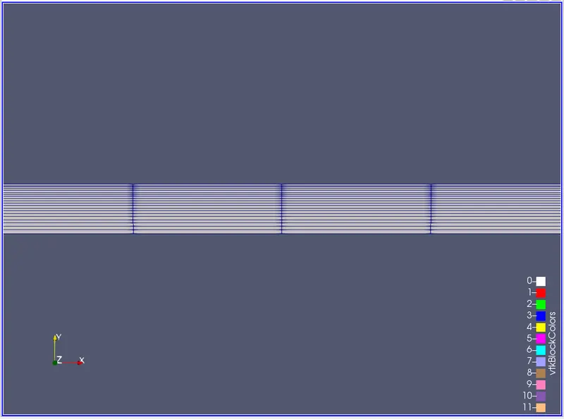
- this is the mesh we are created without using any grading factor it will take default
- along yaxis means along the height of the wedge we are conserdering the grading factor of 0.4 .
- the end cell is 0.4 times smaller than the size of starting cell.
the left side view of the mesh using the view
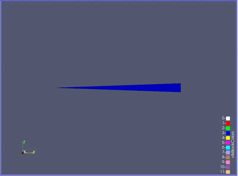
- this image shows the side view of the wedge
- we taken the 20 cell division along the y axis
this is the mesh shown using the wife frame type if we use wire frame type we can see the mesh-like this
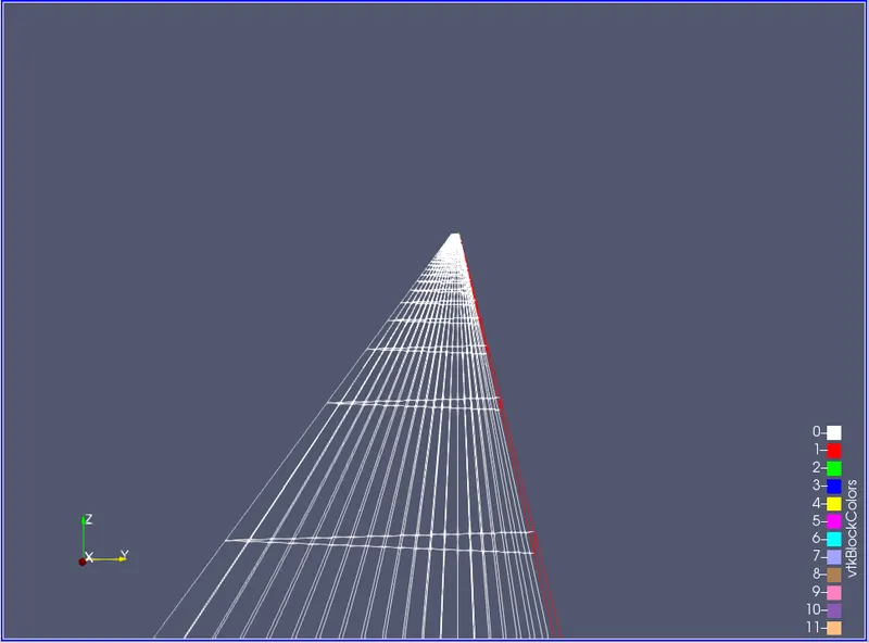
- this figure also showing the mesh.
- but the figure is transparent i.e we have to choose wire frames instead of surface of surface with edges .
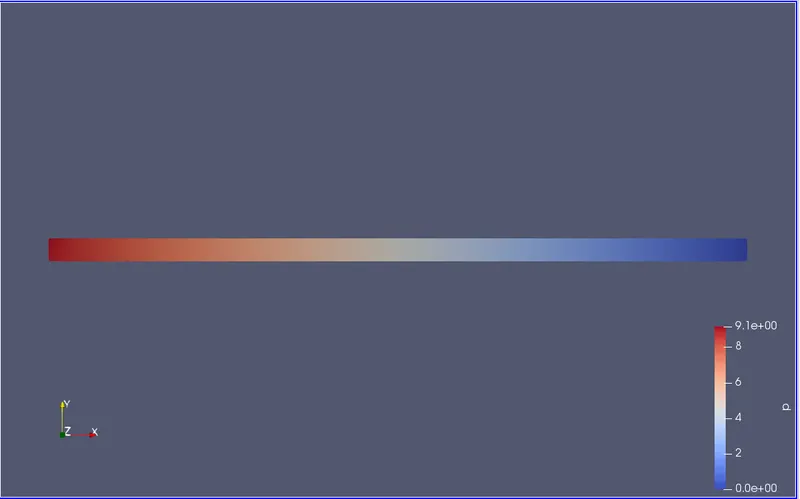
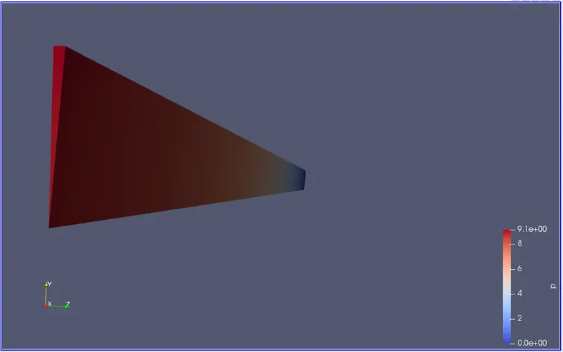
the pressure simulation seen through the 3d view

- this image shows how my pressure going to change along the length of pipe.
- initially the pressure is high but gradually the pressure changes and goes to nearly zero.
- the flow is only because of the pressure difference between the two points of the pipe.
- the red area shows the high pressure and blue area shows the low pressure. the area in between showing the how the pressure is changing along the length of the pipe
the pressure simulation seen throuh the 2d view
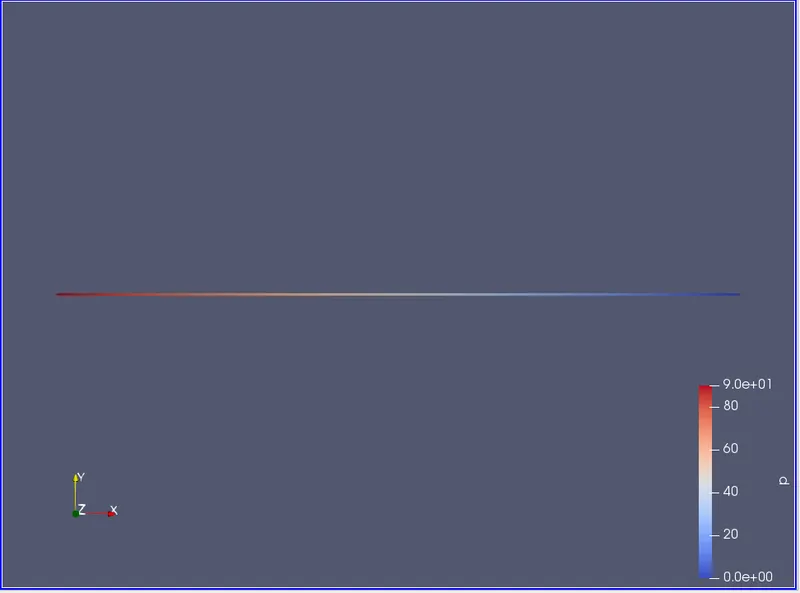
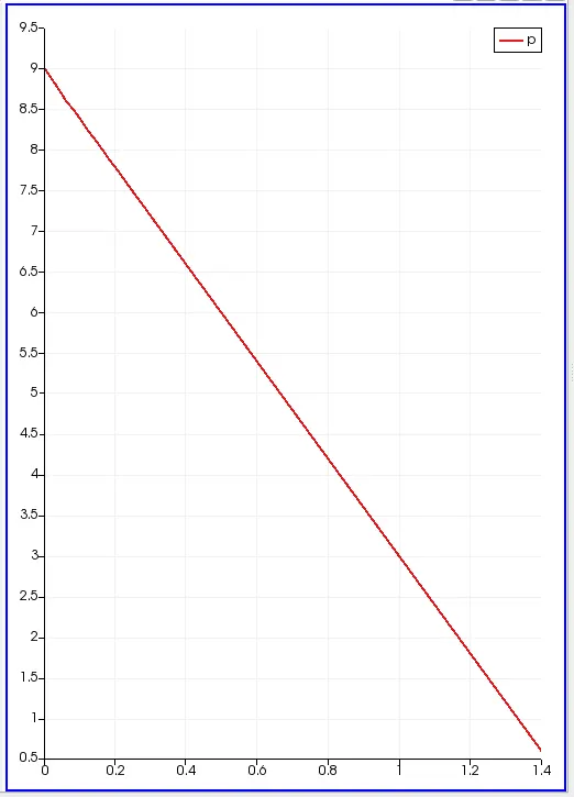
- this figure shows the line that is coloured with the pressure initially the pressure isd very high and then as the distance increases the pressure decreases.
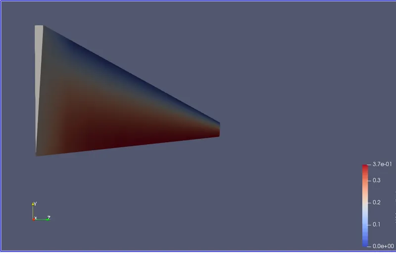
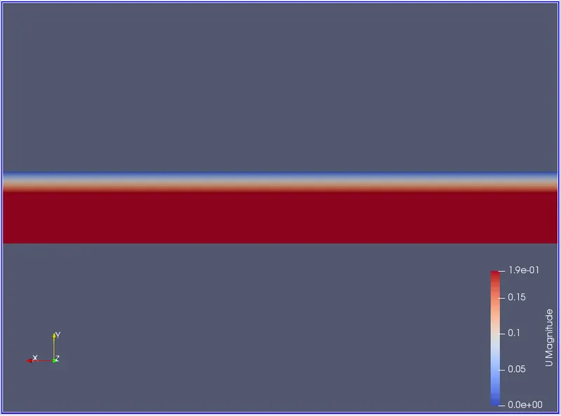
this is the velocity simulation seen through the 3d view
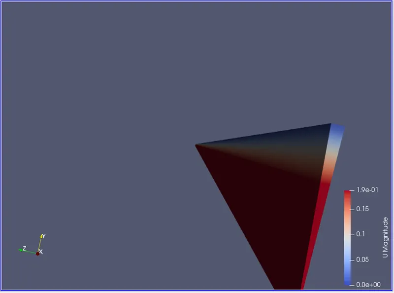
- this figure shows how my velocity will change according to the length of the wedge .
- at the centre portion, the velocity id high because there is no disturbance when compared to the walls
- at the wall we are giving the noi slip condition due to ot this we are getting the velocity nearly equal to zero .
- red colour shows the highest velocity. and blue shows the low velocity, and in between the color shows how velocity will change.
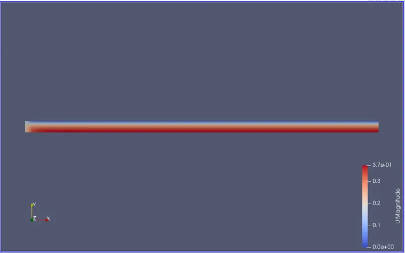
the velocity simulation saw through 2d view
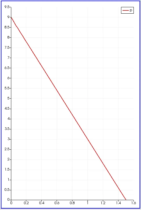
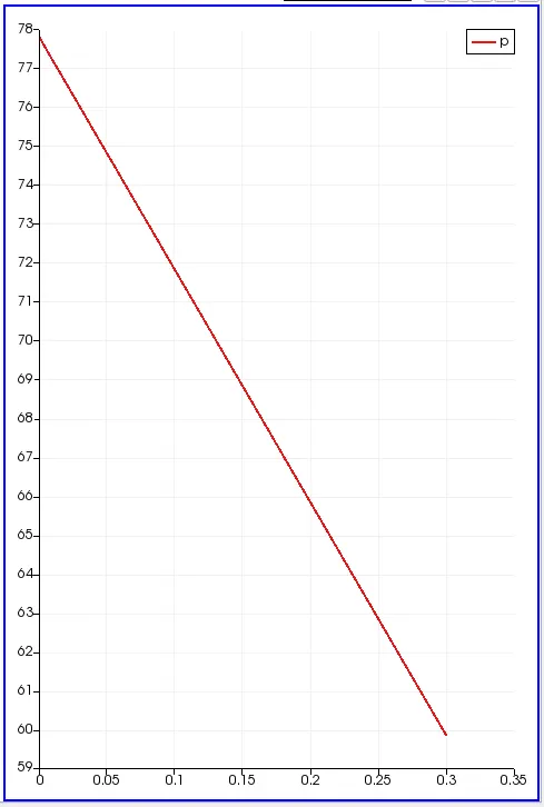
the pressure drop across the length of the pipe (between the length 0.1 and 0.5)
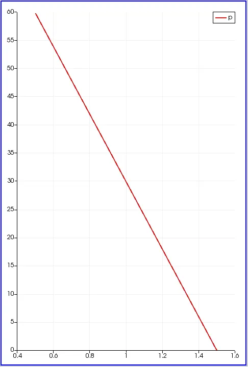
- this curve showing the how my pressure is going to change according to the length of the pipe
- initially the pressure was high and the pressure gradually decreases the end of the pipe the static pressure id nearly equal to zero.
- but the dynamic pressure is not zero due to this pressure difference the fluid is flowing inside the domain
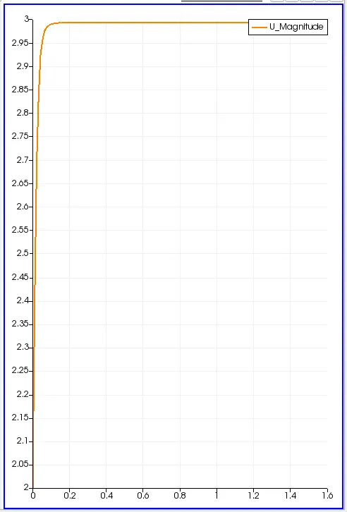
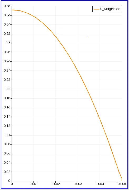
velocity varying at the radial distance ( how my velocity is changing between the centre and the radius of the radius)
its initial velocity profile measured at the distance of the initial length of the pipe.
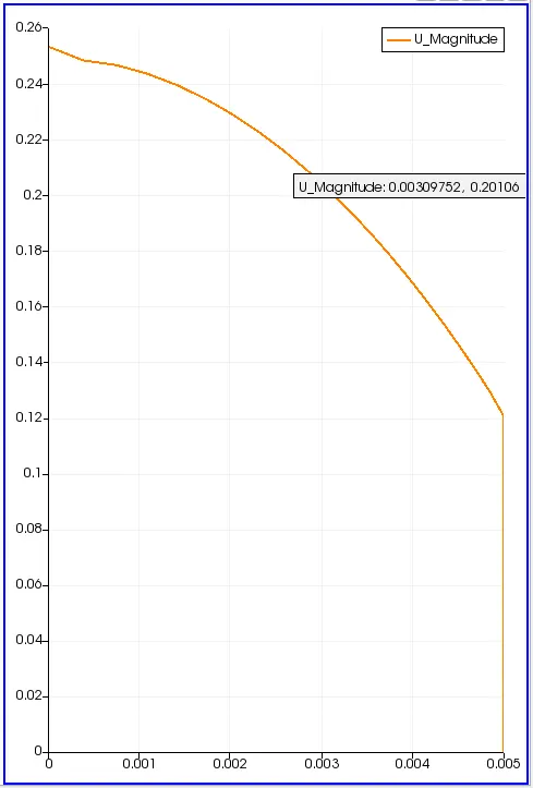
- as the radius increases the velocity is also increasing at the end of the radius the velocity is maximum.
- and very end of the radius the fluid attached to the surface of the pipe the velocity is zero that is because of the viscosity
this is the velocity profile across the length of the pipe
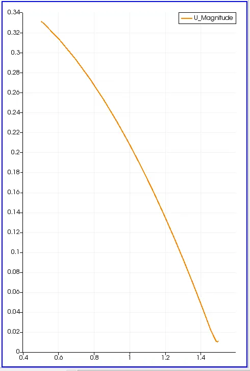
this is the pressure measured between the lengfth o f the 0.2 and 0.5
velocity measured along with the radial length of the pipe
wall shear stress along with the flow along the fully developed velocity profile
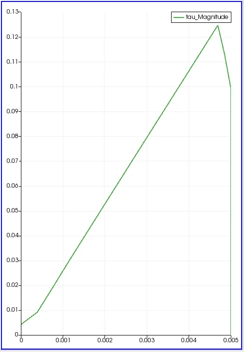
- as the radial distance increases the shear stress also increases.
- the shear stress tou is directly proportional to an increase in dynamic viscosity as the dynamic viscosity increases the shear stress also increases. in this case the dynamic viscosity of water is mu = 0.00089.
THESE ARE THE RESULTS FOR THE PIPE WHICH IS HAVING THE DIAMETER OF 100 mm
RESULTS:
the generation of the mesh using the grading factor
the cells(divisions) along the length of the wedge = 150
the (cells) divisons along the length of the y axis = 20
the cells(divisions) along the mlength of the z axis= 1 because we consider it as the two dimentional flow
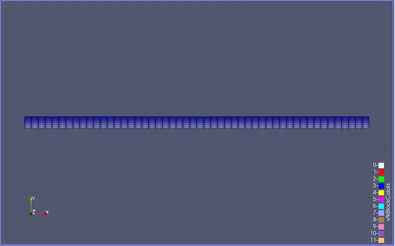
to see this view we have to select the option in the type wire frames then we can see this view
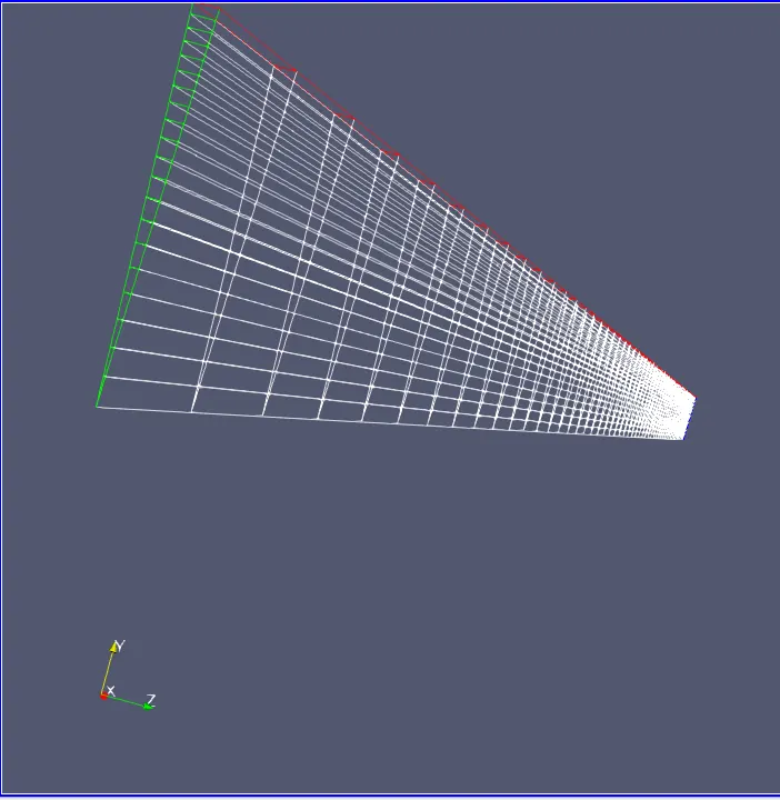
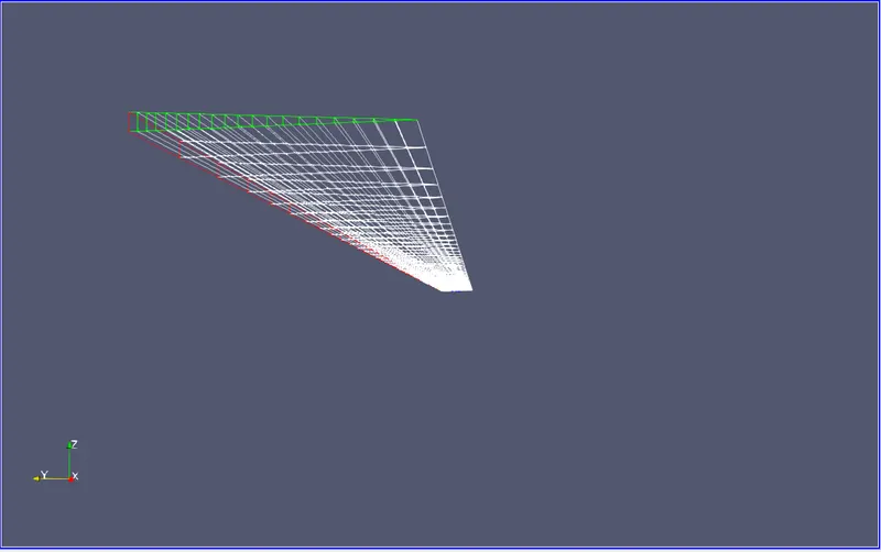
this is the mesh we are generating using the grading factor of 0.5 along the y axis. that is our end cell of the y-axis is 0.5 smaller than the first cell
and along the z-axis that is the length. we are not using any grading factor along the length there is no cross-sections or irregularities so we don't need to grade the mesh along the length of the wedge.
velocity profile at the at length = 0.05
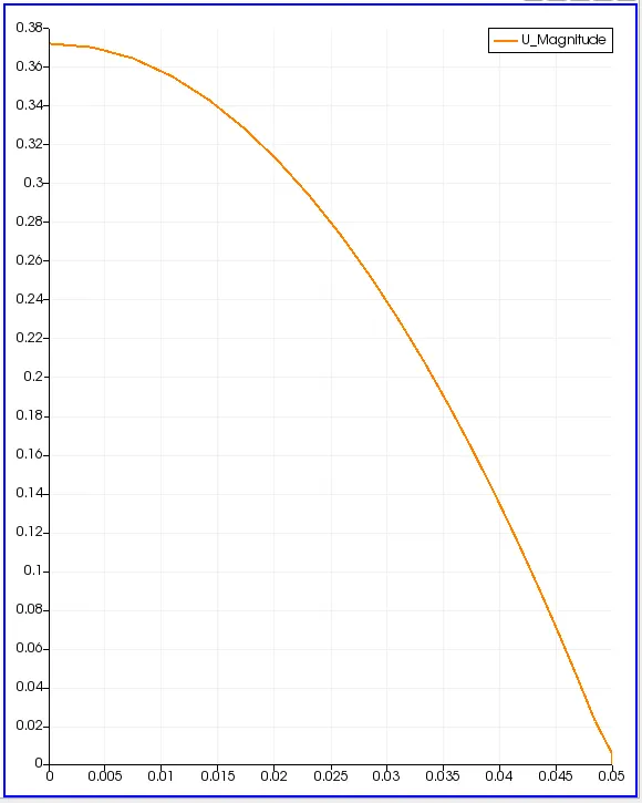
this is the velocity profile at the distance 0.05 that is the radius of the pipe or radius of the wedge as the at the point exactly 0.05 the velocity is nearly equal to the zero and as the diameter (radius) decreases the velocity increases and at the centre of the pipe, it attains the maximum value that is 0.38 m/s.
the pressure along the length of the pipe or wedge.