Week 11 - Simulation of Flow through a pipe in OpenFoam
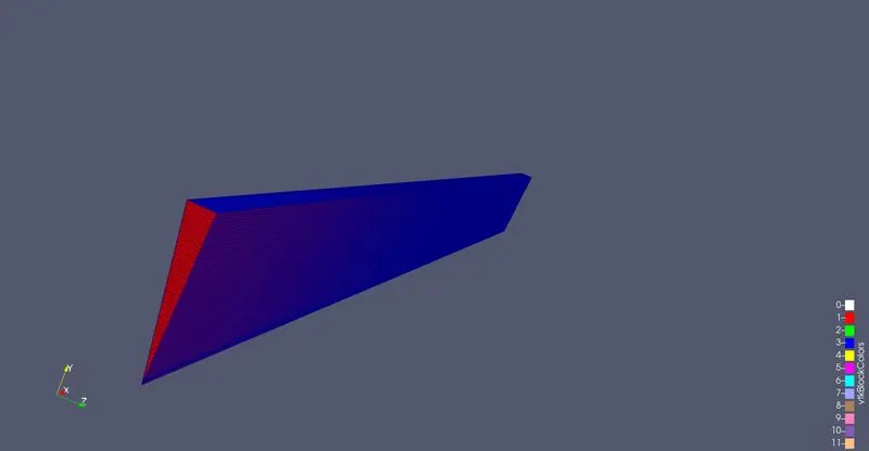
For this problem, a wedge shape portion (wedge angle is 10 deg) is selected from a cylinder of radius 5 cm and length 50 cm.
For inlet and outlet, "patch" boundary conditions are adopted. For wedge, "wedge" boundary is adopted. The top portion is selected as a wall. The axis is selected as empty.
The blockmeshdict file is as follows:
/*--------------------------------*- C++ -*----------------------------------*\
  =========                 |
  \\      /  F ield         | OpenFOAM: The Open Source CFD Toolbox
   \\    /   O peration     | Website:  https://openfoam.org
    \\  /    A nd           | Version:  9
     \\/     M anipulation  |
\*---------------------------------------------------------------------------*/
FoamFile
{
    format      ascii;
    class       dictionary;
    object      blockMeshDict;
}
// * * * * * * * * * * * * * * * * * * * * * * * * * * * * * * * * * * * * * //

convertToMeters 0.01;

vertices
(
    (0 0 0)
    (50 0 0)
    (50 4.98097 -0.43578)
    (0 4.98097 -0.43578)
    (50 4.98097 0.43578)
    (0 4.98097 0.43578)

);

blocks
(
    hex (0 1 2 3 0 1 4 5) (400 50 1) simpleGrading (1 1 1)
);

edges
(
	arc 5 3 (0 4.99695 0.174497)
	arc 4 2 (50 4.99695 0.174497)
);

boundary
(
    inlet
    {
        type patch;
        faces
        (
            (0 5 3 0)
        );
    }

    outlet
    {
        type patch;
        faces
        (
            (1 2 4 1)
        );
    }


    top
    {
        type wall;
        faces
        (
            (3 5 4 2)


        );
    }


    left
    {
        type wedge;
        faces
        (
            (0 3 2 1)

        );
    }

    right
    {
        type wedge;
        faces
        (
            (1 4 5 0)

        );
    }

    axis
    {
        type empty;
        faces
        (
            (0 1 1 0)

        );
    }


);

mergePatchPairs
(
);

// ************************************************************************* //
the mesh thus generated is as follows:
For the satisfaftion of courant number and to remain in laminar regine following U file is created:
/*--------------------------------*- C++ -*----------------------------------*\
  =========                 |
  \\      /  F ield         | OpenFOAM: The Open Source CFD Toolbox
   \\    /   O peration     | Website:  https://openfoam.org
    \\  /    A nd           | Version:  9
     \\/     M anipulation  |
\*---------------------------------------------------------------------------*/
FoamFile
{
    format      ascii;
    class       volVectorField;
    object      U;
}
// * * * * * * * * * * * * * * * * * * * * * * * * * * * * * * * * * * * * * //

dimensions      [0 1 -1 0 0 0 0];

internalField   uniform (0 0 0);

boundaryField
{
    inlet
    {
        type            fixedValue;
        value           uniform (10 0 0);
    }

    outlet
    {
        type            zeroGradient;
    }

    top
    {
        type            noSlip;
    }

    left
    {
        type            wedge;
    }

    right
    {
        type            wedge;
    }

    axis
    {
        type            empty;
    }

}

// ************************************************************************* //
Like wise the pressure file is as follows:
/*--------------------------------*- C++ -*----------------------------------*\
  =========                 |
  \\      /  F ield         | OpenFOAM: The Open Source CFD Toolbox
   \\    /   O peration     | Website:  https://openfoam.org
    \\  /    A nd           | Version:  9
     \\/     M anipulation  |
\*---------------------------------------------------------------------------*/
FoamFile
{
    format      ascii;
    class       volScalarField;
    object      p;
}
// * * * * * * * * * * * * * * * * * * * * * * * * * * * * * * * * * * * * * //

dimensions      [0 2 -2 0 0 0 0];

internalField   uniform 0;

boundaryField
{
    inlet
    {
        type            zeroGradient;
    }

    outlet
    {
        type            fixedValue;
        value		uniform 0;
    }

    top
    {
        type            zeroGradient;
    }

    left
    {
        type            wedge;
    }
    right
    {
        type            wedge;
    }

    axis
    {
        type            empty;
    }


}

// ************************************************************************* //
The time step ending and starting times are as follows (in controldict file):
/*--------------------------------*- C++ -*----------------------------------*\
  =========                 |
  \\      /  F ield         | OpenFOAM: The Open Source CFD Toolbox
   \\    /   O peration     | Website:  https://openfoam.org
    \\  /    A nd           | Version:  9
     \\/     M anipulation  |
\*---------------------------------------------------------------------------*/
FoamFile
{
    format      ascii;
    class       dictionary;
    location    "system";
    object      controlDict;
}
// * * * * * * * * * * * * * * * * * * * * * * * * * * * * * * * * * * * * * //

application     icoFoam;

startFrom       startTime;

startTime       0;

stopAt          endTime;

endTime         0.2;

deltaT          0.0001;

writeControl    timeStep;

writeInterval   5;

purgeWrite      0;

writeFormat     ascii;

writePrecision  6;

writeCompression off;

timeFormat      general;

timePrecision   6;

runTimeModifiable true;


// ************************************************************************* //
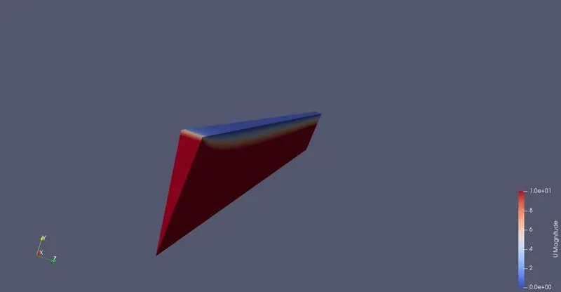
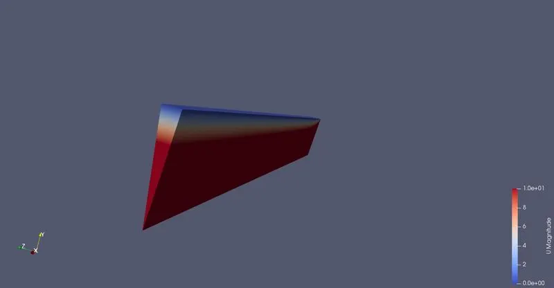
The contour plot of inlet and exit section are as follows:
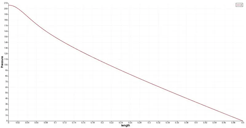
The pressure variation at different length is as follows:
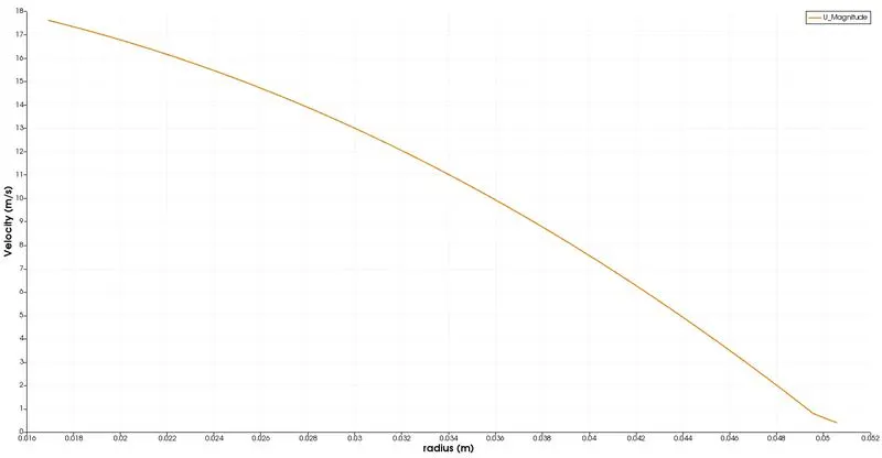
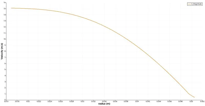
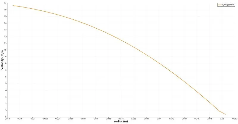
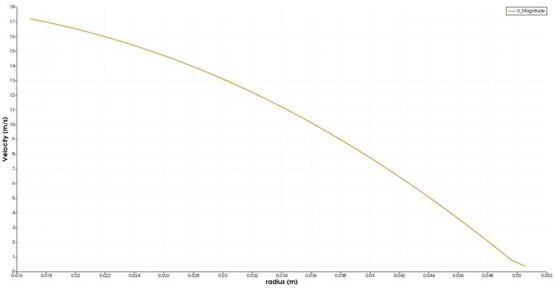
The velocity variation at different locations along the length of cylinder are as follows:
0.1m
0.2 m
0.3 m
0.4 m
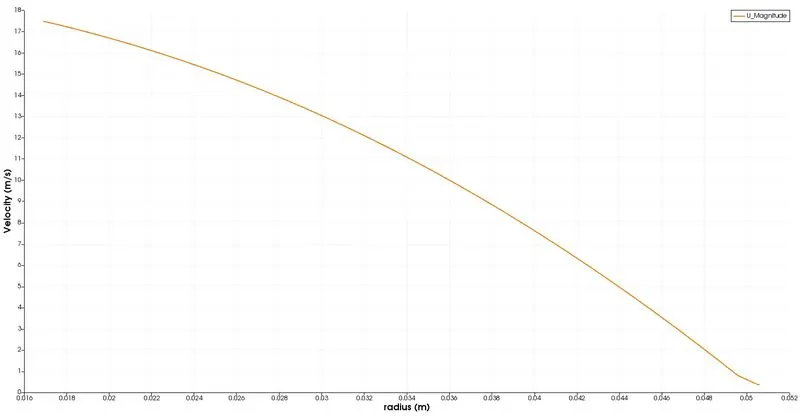
0.5 m