Week 11 - Project - A pillar Design with Master Section
A PILLAR DESIGN WITH MASTER SECTION:
OBJECTIVE:
To design 'A pillar' component of a vehicle whith given class A surface along with master section for engineering feature as an input.
INTRODUCTION:
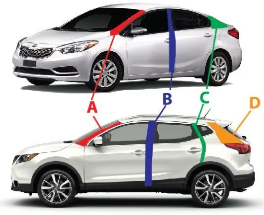
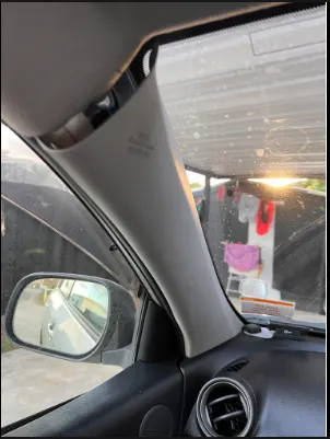
The A pillar is the structural upright that partially frames the windshield. A-pillars (one on each side of the body) are joined across the top of the windshield by the header rail. The base of the windshield where it meets the hood is called cowl. The portion of the roof that joins A-pillars, B-pillars, C-pillars together to form the vehicles roof structure is known as 'cant rail'.
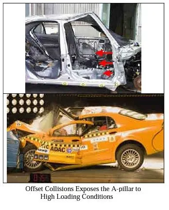
To obtain a strong roof one of the most important vehicle structure components is the A-pillar. There are conflicting requirement on the A-pillar of a passenger vehicle. For ocupant protection the A-pillar needs to be stiff and strong to withstand the load in a rollover or a frontal impact at high impact velocity. However, the A-pillar obscures the vision for the driver. Therefore, for the vehicle driver to have good visibility the A-pillar needs to be slim (have a small cross section).
Hence the A-pillar design should be slim as well as stiff and strong to carry the accidental impact.
Types of pillars in a car:
SEQUENCE OF OPERATION:
- Understanding class A surface
- Creating tooling axis
- Draft analysis for class A surface
- Creating class B surface
- Creating class C surface
- Adding engineering features to the product
- Draft analysis for final solid plastic component
1.) Understanding class A surface:
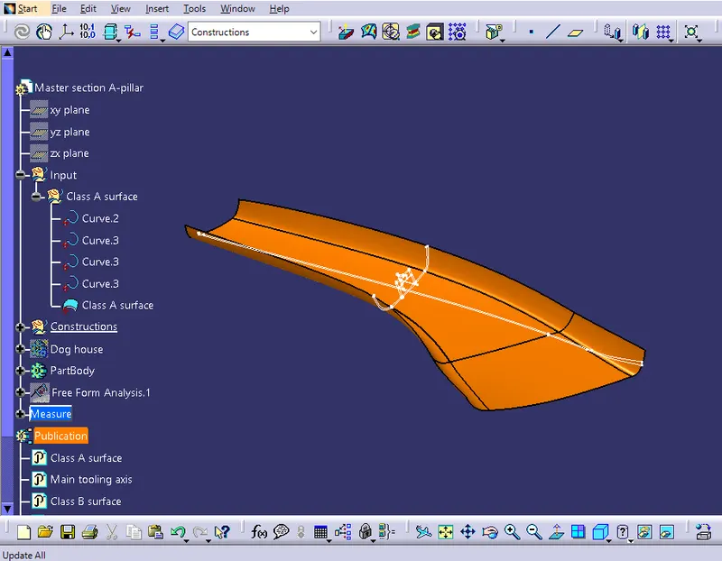
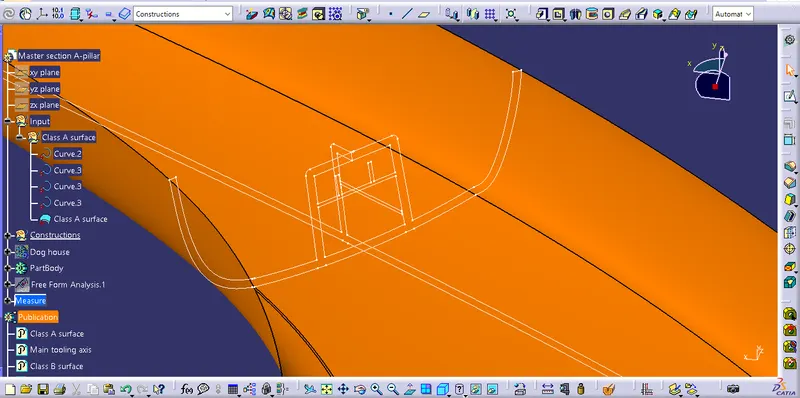
The class A surface is the visible and aesthetic side of the part. The class A surface is created from hand sketch and developed in a software called Alias. The class A surface is developed into plastic product with engineering features along B side surface.
Given class A surface with master section for engineering features:
2.) Creating main tooling axis:
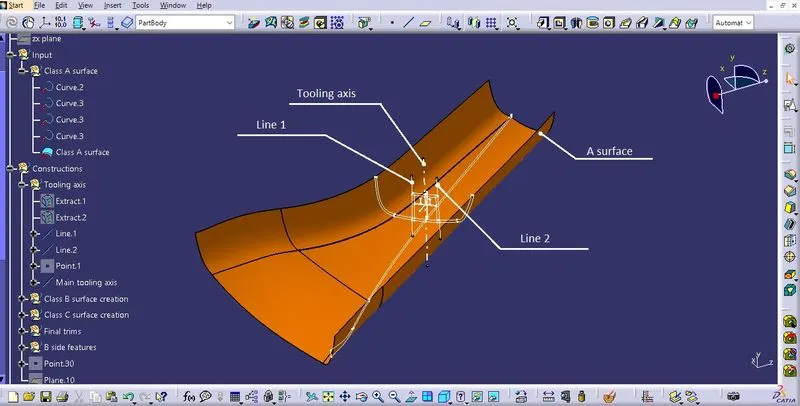
Tooling axis is the important aspect for a designer to create. It is responsible for the mold movement (core & cavity), tooling axis should clear the draft analysis. Tooling axis should be ease for manufacturing. Complicated tooling axis can increase cost and time for manufacturing.
The tooling axis is created by bisecting method.
3.) Draft analysis for class A surface:
Each component is created with minimum draft angle, the draft angle allows for easy ejection of component from the mold. The draft analysis show the draft value in each surface. The tooling axis should clear the draft analysis.
The nominal draft angle is 3°
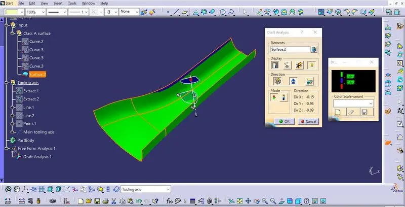
Some area shows a minimum draft value of 2.5° which is accepted.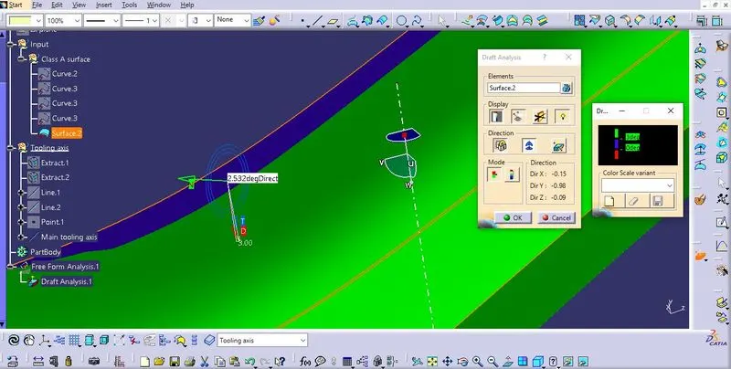
4.) Class B surface creation:
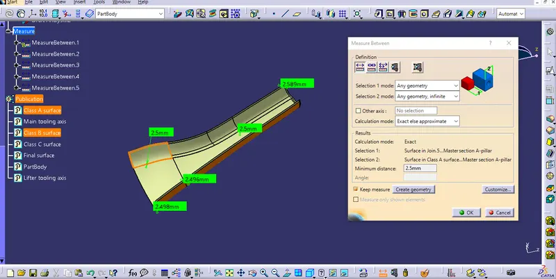
The thickenss of the component is 2.5mm.
The B surface is created by offsettting A sufrace and minor patches are rectified by using tools like multiple extract, extrapolate, trim and join.
5.) Class C surface creation:
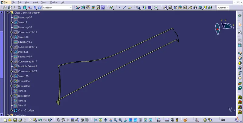
The class C surface is created by using tools like multiple extract, boundary, sweep, trim join. It is swept from class A surface using the tooling axis.
The class C surface is joined with class A surface and trimmed with class B surface to form the final surface and closed boundary condition is checked.
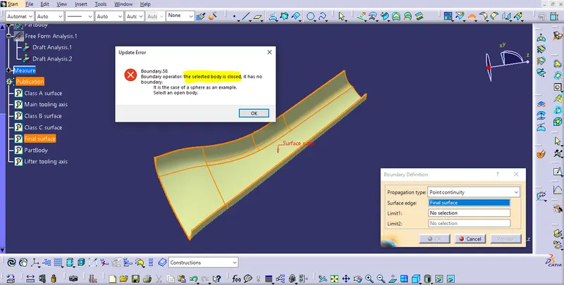
The closed surface is converted to solid part.
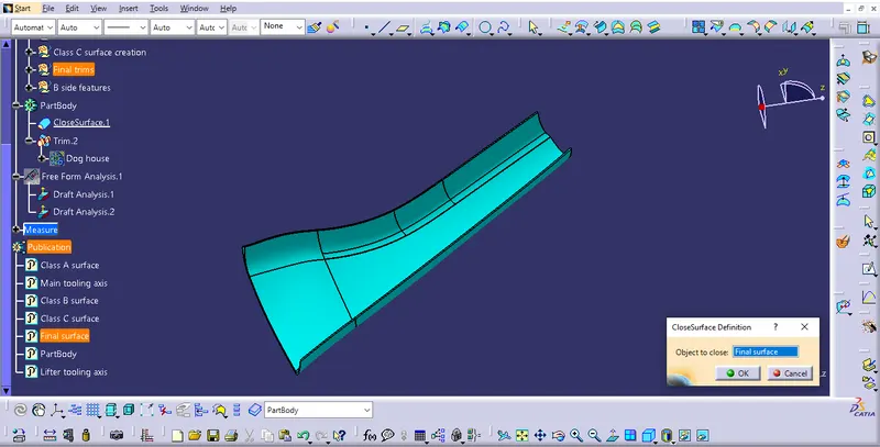
6.) Creating dog house engineering feature in B surface:
Dog house - It is an engineering features in plastic trim design. It is used as a supporting feature in which locator, screw boss, push pin are mounted onto it.
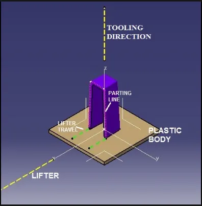
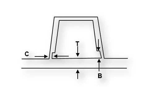
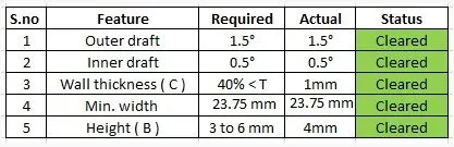
The dog house feature is created by using the design rules:
Status:
The dog house required required tow different tooling axis
- Main tooling axis (for the outer part)
- Lifter tooling axis (for internal undercut)
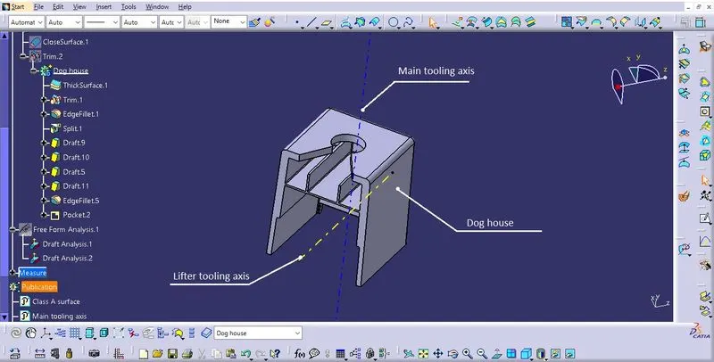
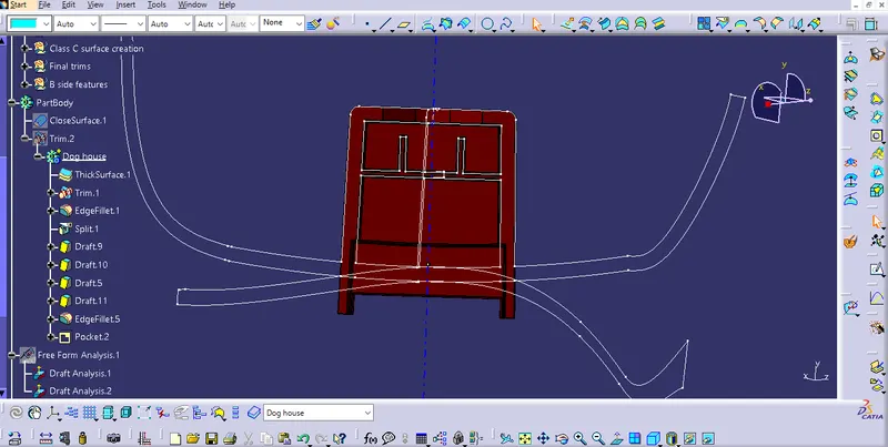
The dog house is created with the given master section:
Draft analysis for dog house:
Main tooling axis:
The draft angle outer is given 1.5°
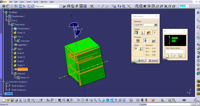
Lifter tooling axis:
The draft angle given to the lifter is 0.5°
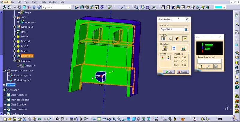
The cutout is taken from the given drawing:
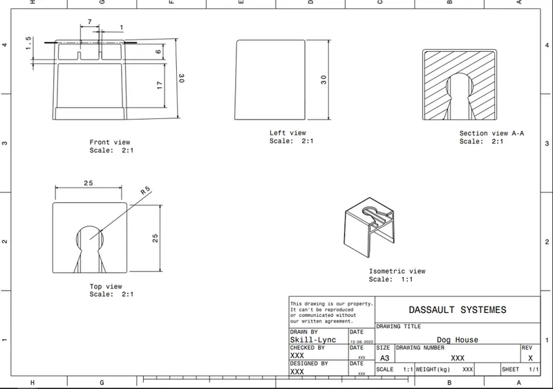
It is then union trimmed with the part body to form the final plastic product.
7.) Draft analysis for final component:
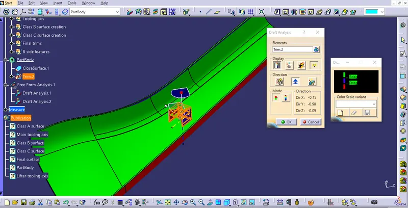
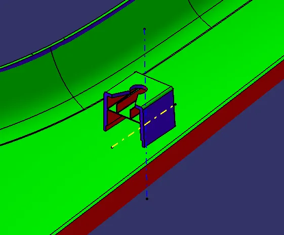
The draft angle for final plastic product is cleared.
The area which is in 'green' are at 3° draft
The area which is in 'blue' are in 2.5°
The area which is 'blue' for dog house is 1.5° which are accepted.
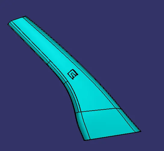
Final product:
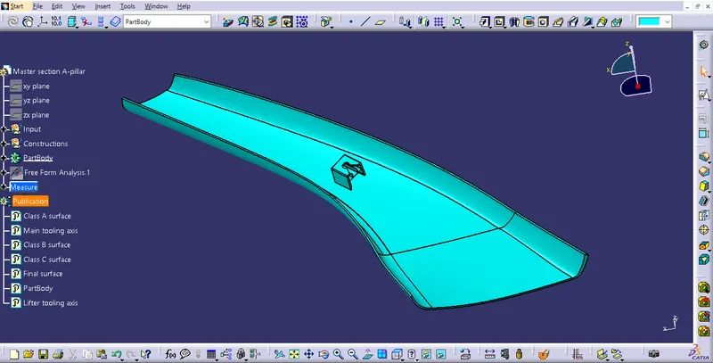
CONCLUSION:
Thus the final plastic product is created with the dog house engineering features in it.
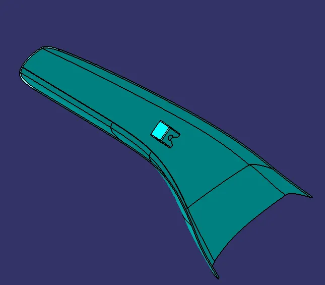
3D part model:
Iso-metric view:
Front view:
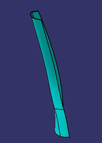
Side view:
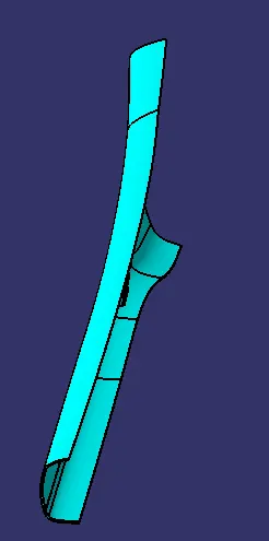
Top view:
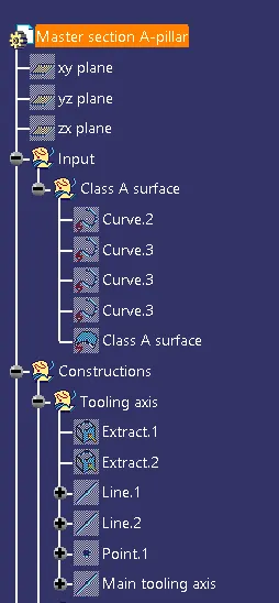
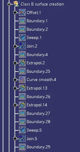
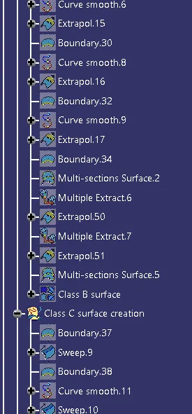
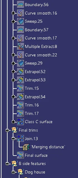
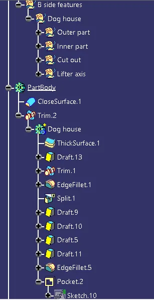
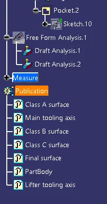
Tree structure:
Sketch solving status: