Week 11 - Project - A pillar Design with Master Section
A-PILLAR WITH MASTER SECTION
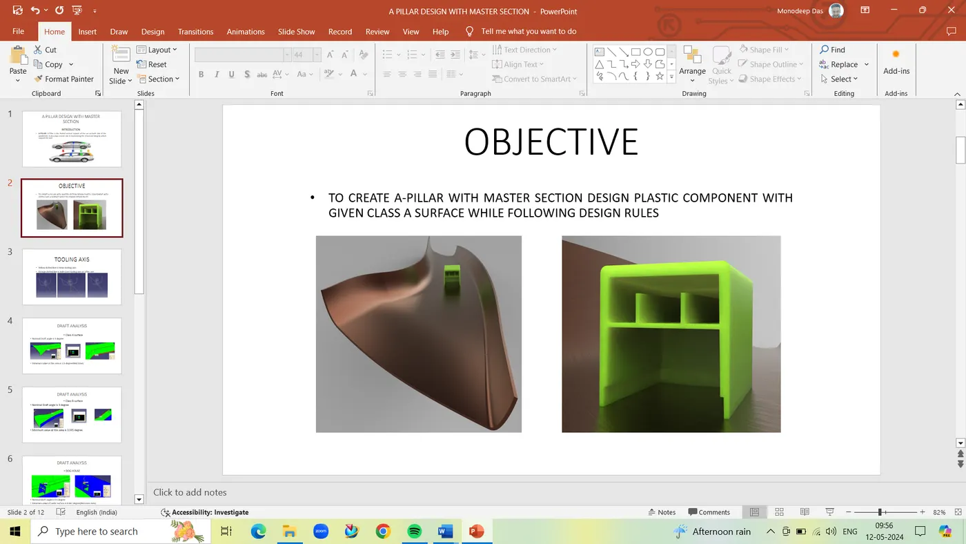
AIM- To create the A-pillar’s Plastic component from the given Class A surface by using the master section provided with design rules.
INTRODUCTION
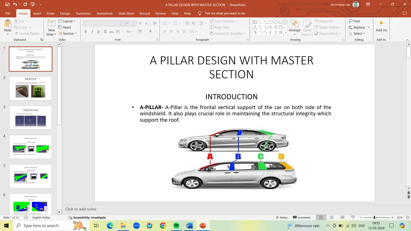
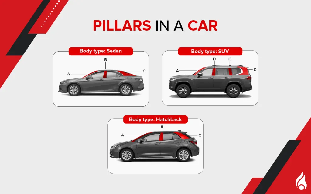
The pillar on a car with permanent roof body style are vertical or nearly vertical supports of its window area designated respectively as A, B, C pillars (4-door sedan, coupe, hatchback & crossovers) & D pillars (SUV’s, MUV’s, Estates).
They are very much important for stationary structural integrity & provide the strong foundation to install glass (windscreens, side windows, rear screen & even rear quarter windows) of a vehicle. It also provides the protection to the occupants in the vehicles in case of frontal crash, rear side crash & even up-side down crash.
TYPES OF PILLARS
A_PILLARS- A-Pillar is the frontal vertical support of the car on both side of the windshield. It also plays crucial role in maintaining the structural integrity which support the roof.
B_PILLARS- B-Pillar is the 2nd pillar which is located in between front & rear side of glass (i.e. between the front &rear door on both sides) where it serves the structural support of the roof.
C_PILLAR- C-Pillar is the 3rd pillar which is the rearmost support of 4-door sedan, coupe, hatchback & crossovers.
D_PILLAR- D-Pillar is the 4th pillar which usually seen in large vehicles like SUV’s, MUV’s, Estates.
MAIN REPORT
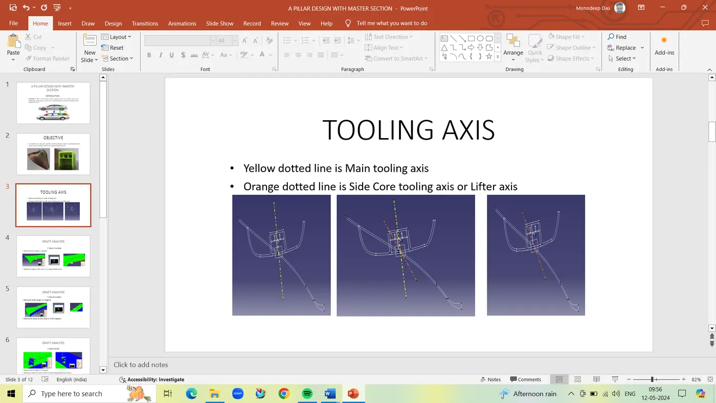
· TOOLING AXIS-
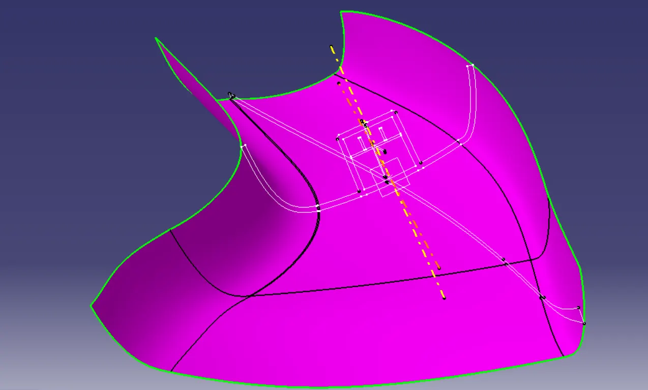
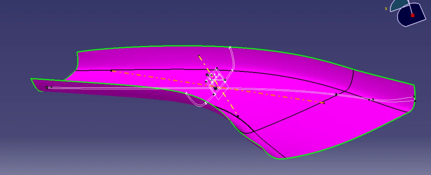
Extract the lines from the given master section & bisect the extracting line through line commands. Mid-line is generated between the extracted lines, that mid- line is the tooling axis.
Side-core tooling axis or lifter axis is created by selecting the plane.
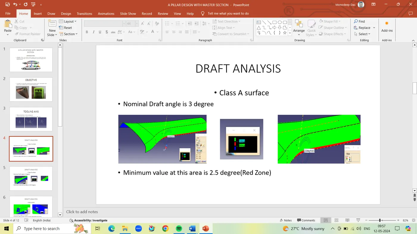
· DRAFT ANALYSIS
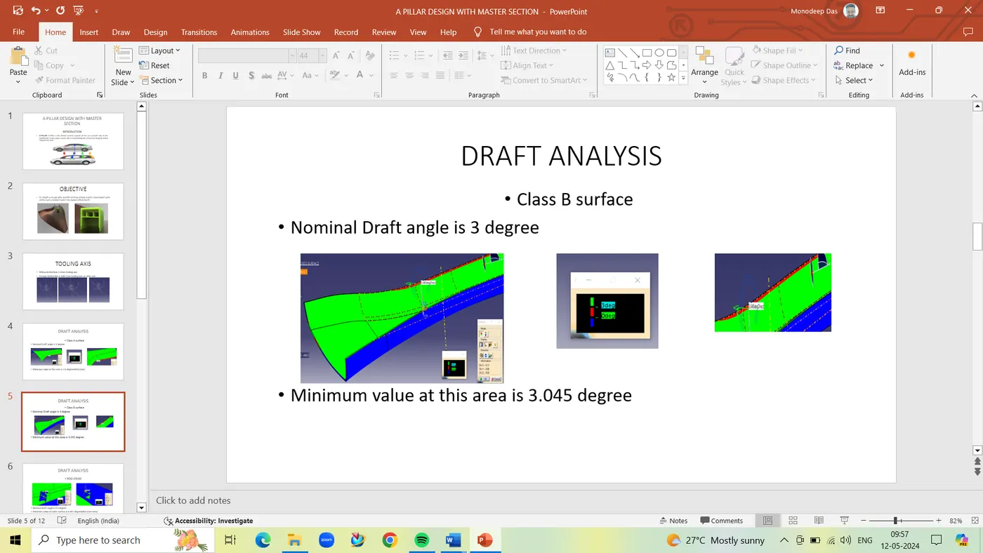
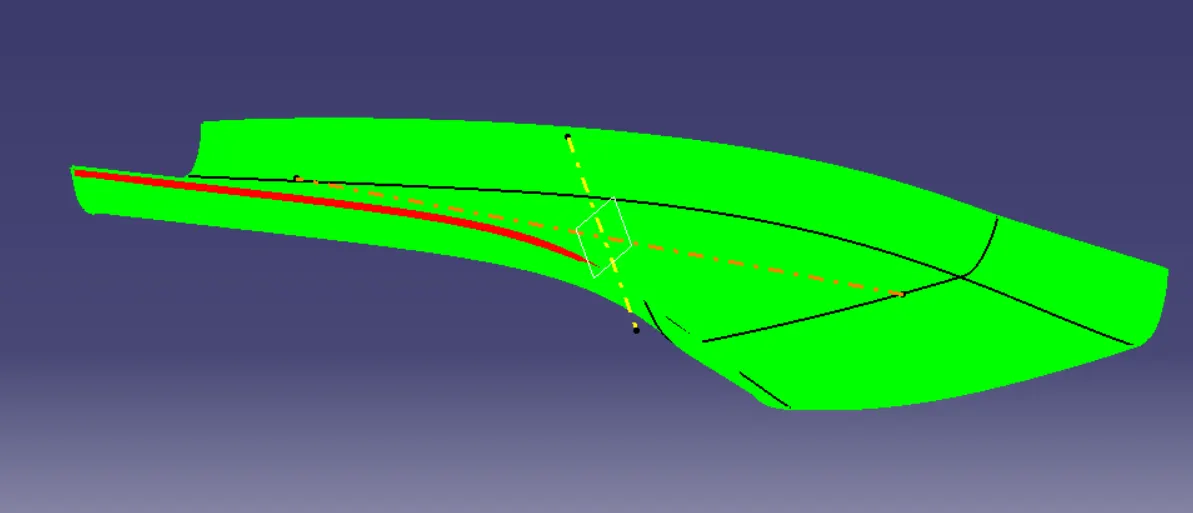
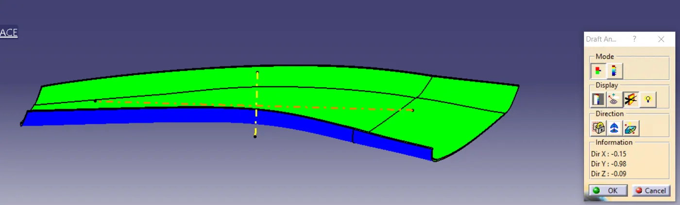
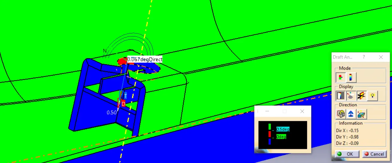
Draft analysis is a command which enable to detect the draft angle of the surface. This type of analysis is performed on the colour ranges to identify the zones on the analysis of the element with references to tooling axis.
Draft analysis on plastic material is checked with reference to tooling axis at minimum angle of 3 degree & showing green colour then it is safe.
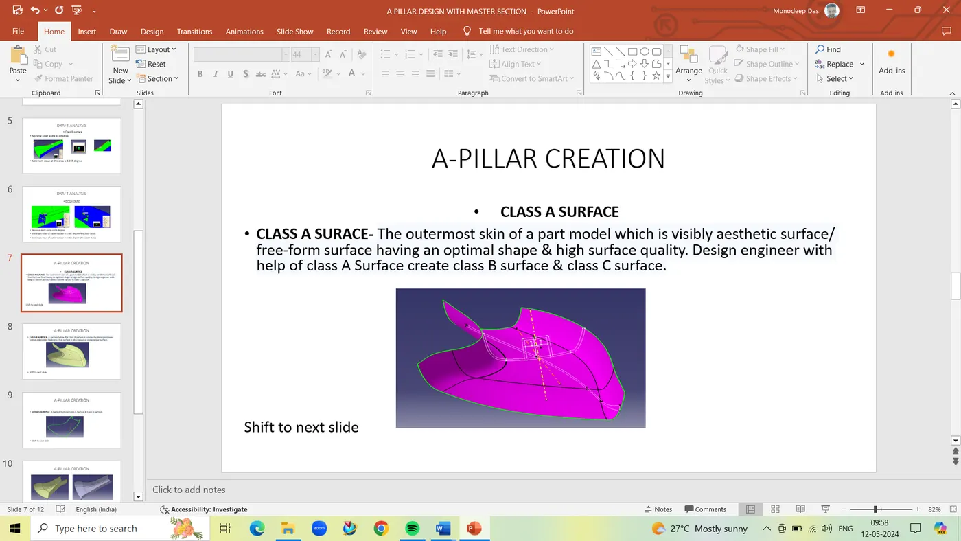
· CLASS B SURFACE
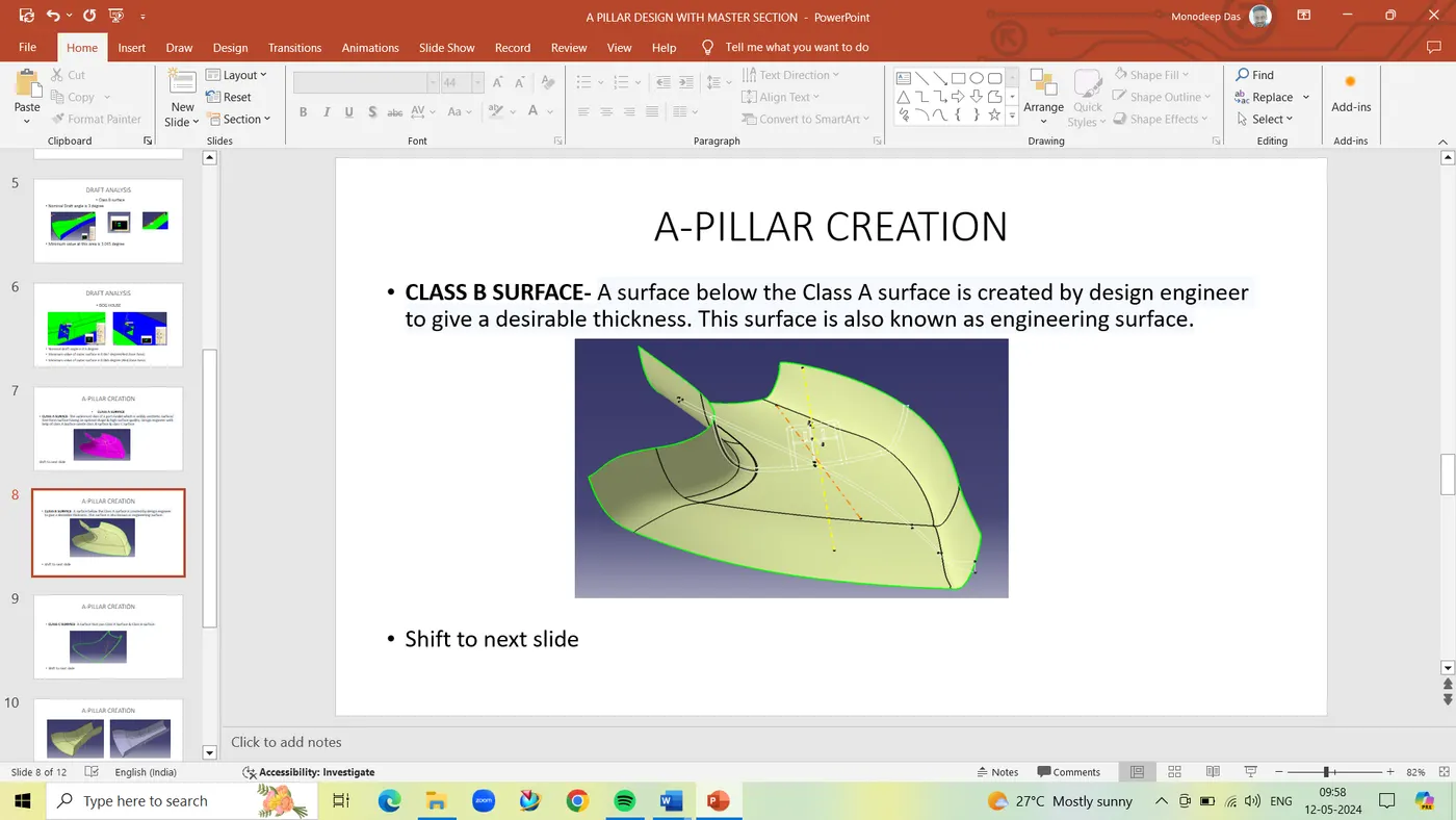
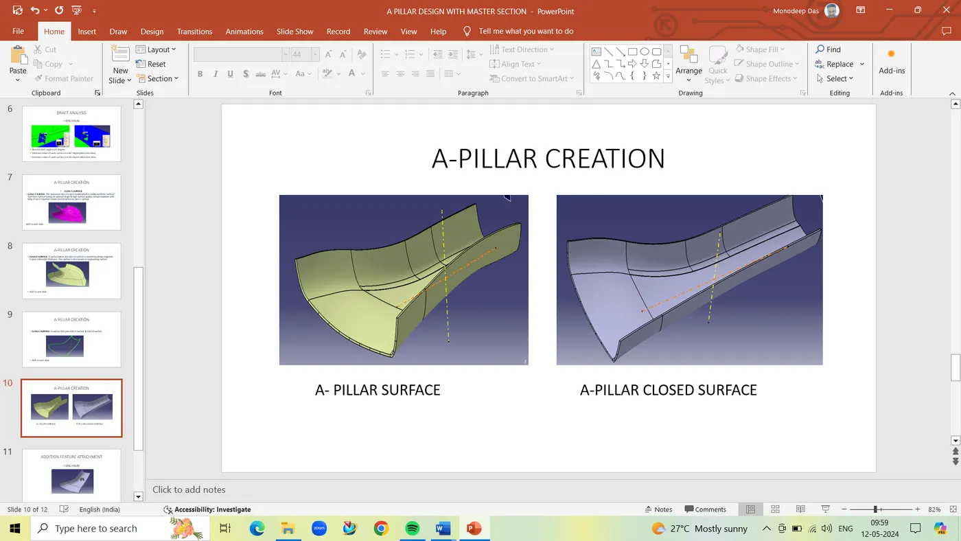
Offset the Class A Surface to 2.5mm inwards. Check with master section which will show the exact fitting of the thickness of the component. After offsetting, some patches are missing in the class B surface which can be Generate by creating boundary through boundary commands. Then sweep the patch through sweep commands. A small patch still present, so blend the patch through blend commands & later join the different surface into one surface by join commands. Check through join command any gaps are present in the surface, if present then render the surface further so that no gap present in the class B surface.
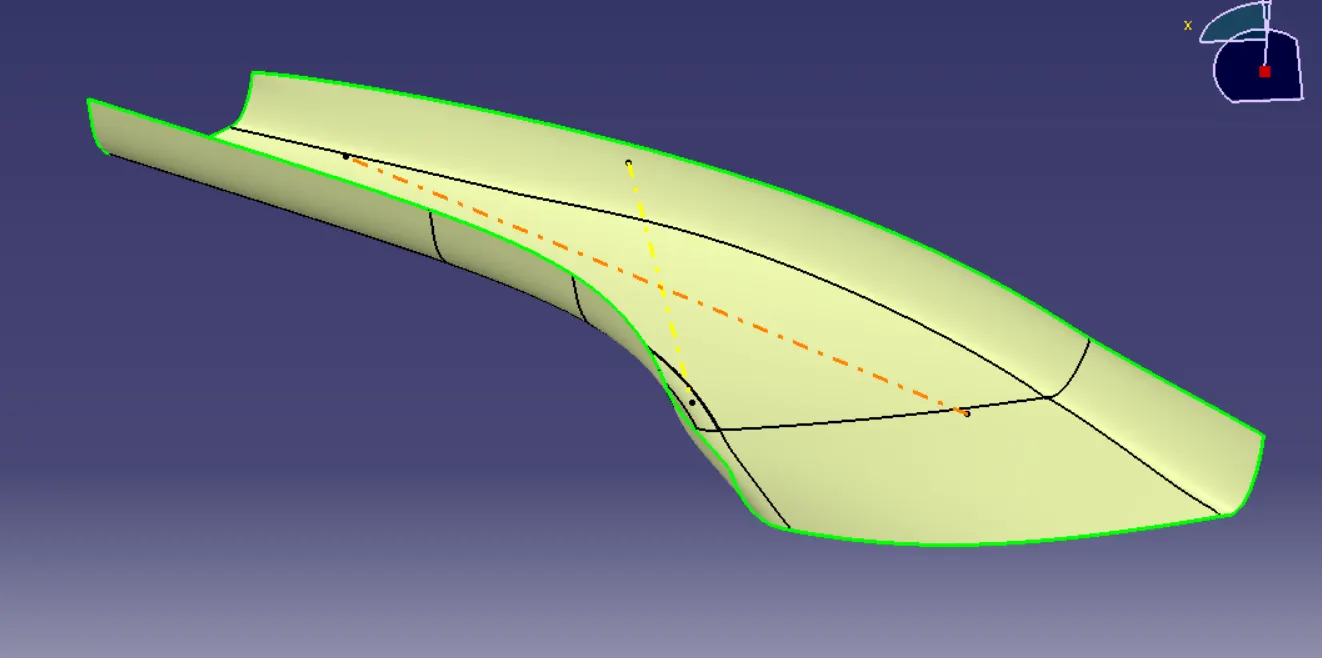
· CLASS C SURFACE
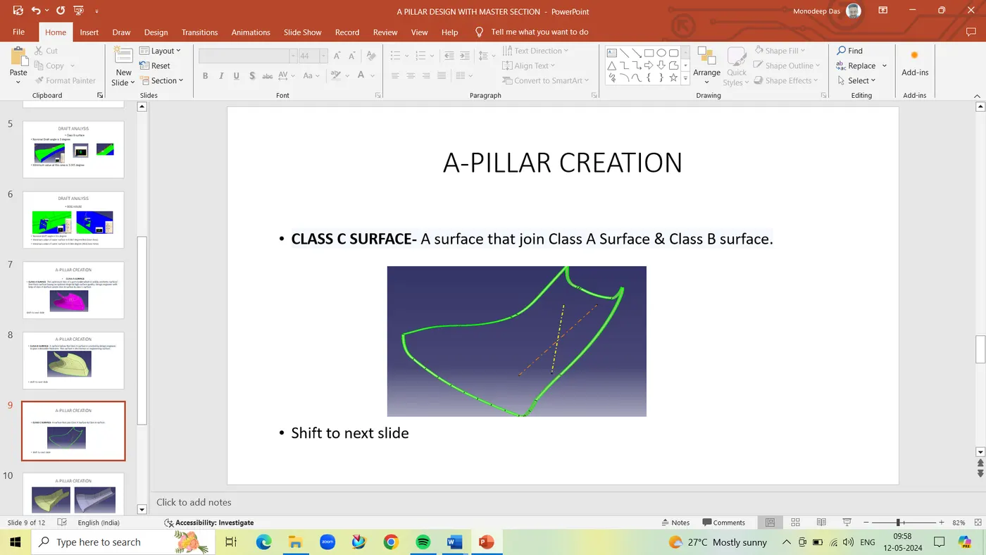
Take the boundary of the Class A surface to create the Class C surface. Go to sweep command, select with refence surface.
If the generated C surface is parallel to the tooling axis create the sweep along the draft direction at angle of 3 degree.
If the surface is perpendicular to the tooling axis, then create the sweep using the reference surface option then extrapolate the connecting surface & trim the surface together & join them all together to form the Class C surface.
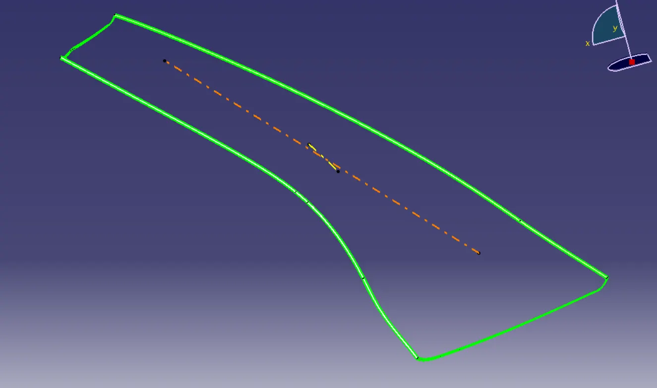
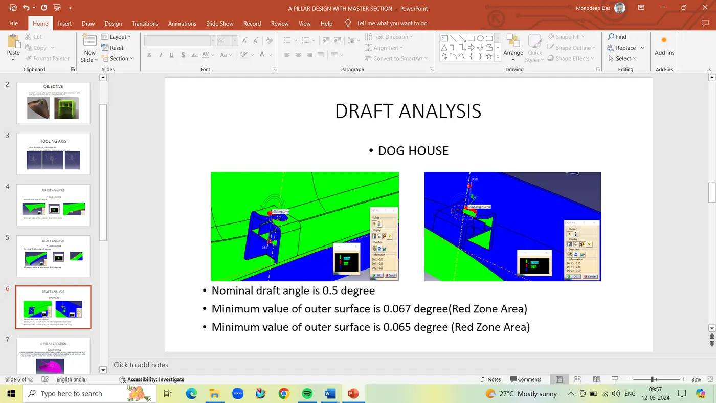
· DRAFT ANALYSIS OF CLOSED SURFACE
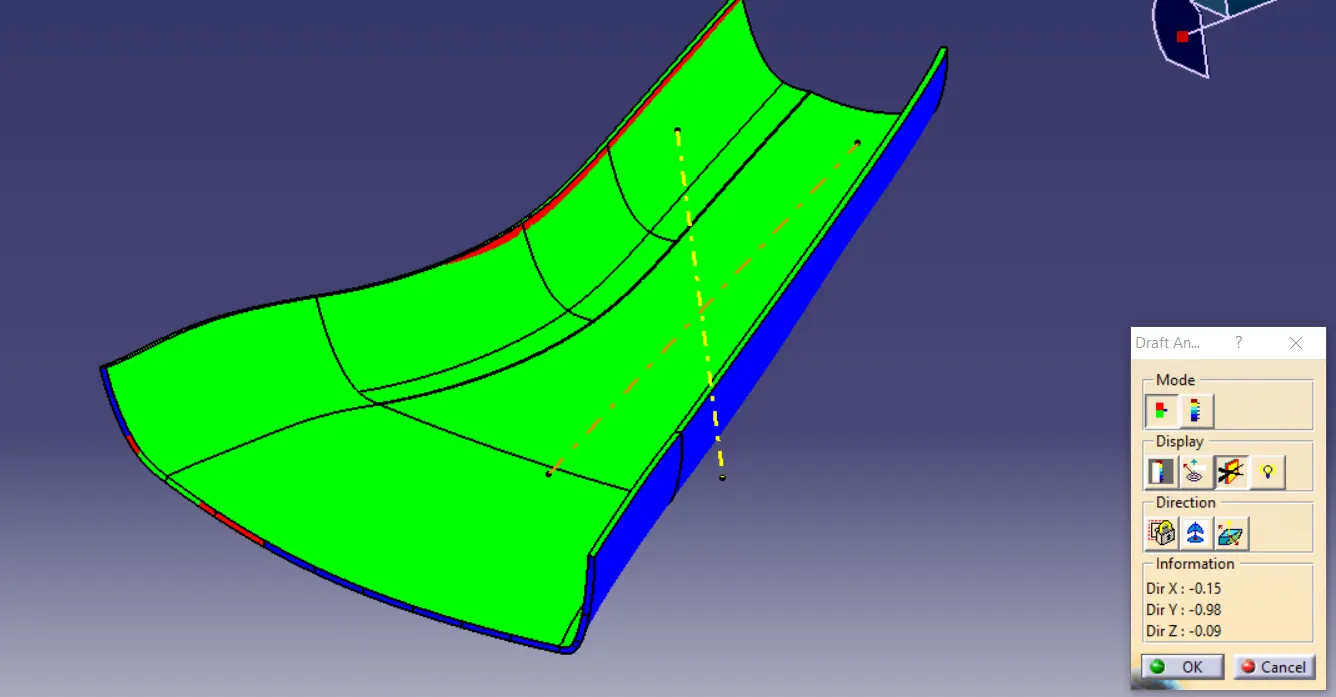
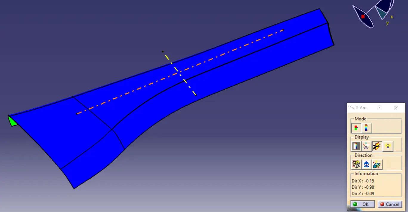
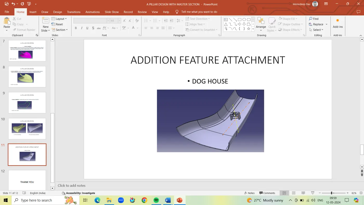
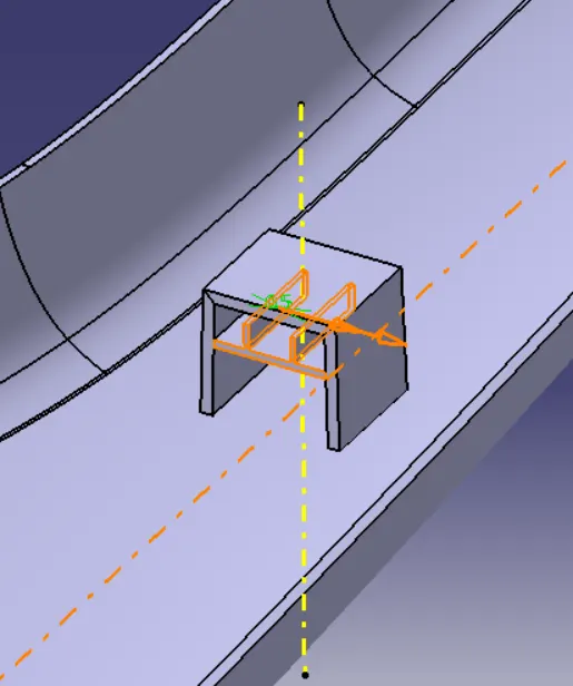
DOG HOUSE CREATION
· First step is to create side core axis.
· Extract the surface & create a sketch.
· Extrude the sketch & for closing the surface use multi-section command. Later join both surfaces.
· Use thicken command in the part workbench.
· Create 1.5-degree draft angle on the outside surface.
· Extract the inside wall of the dog house & offset to 1 mm outward.
· Offset the surface to 4mm upwards & trim it.
· Go to part workbench & use split command.
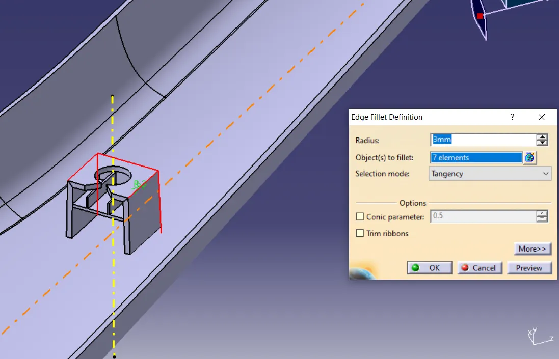
· Draft 0.5 degree & fillet 0.5 mm.
· Fillet the 3mm on the outer walls of the dog house.
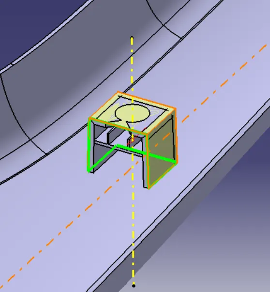
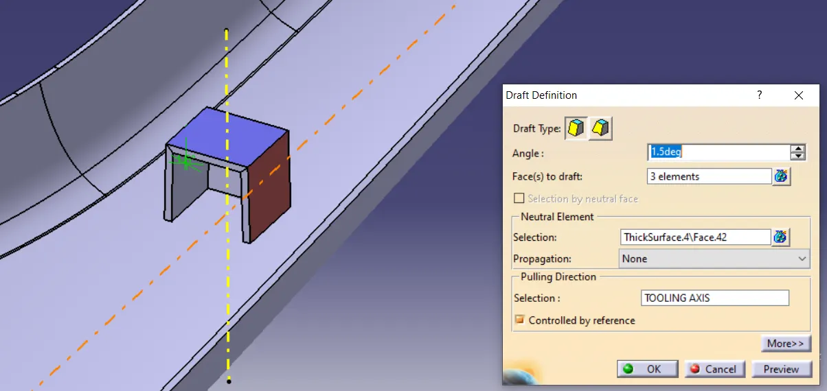
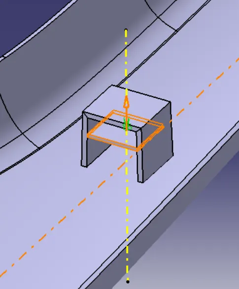
DRAFT ANALYSIS
CONCLUSION
The given challenge has been done with given detail completed successfully.
PRESENTATION OF A-PILLAR WITH MASTER SECTION (PPT)