Week 11 - Project - A pillar Design with Master Section
Design of A Pillar Master Section
Objective:
- To design A PILLAR MASTER SECTION with respect to the class a surface.
- Create class b surface and class c surface and the tooling Axis
- Convert those class A surfaces in a close body and make it into the solid body provide the thickness of 2.5 mm
- Performing draft analysis to verify the creation of tooling axis and class C surface.
- To create the dog house according to the intersection given with the class A surface
The class a surface and the Master-section is given below
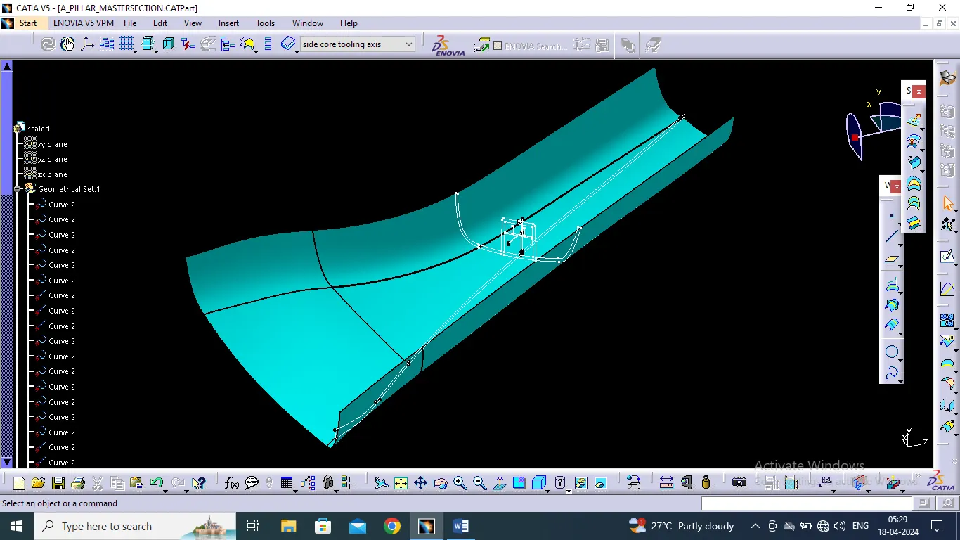
Here we are using CATIA V5 Generative Shape Design for further surface developements..
Creation of Main Tooling Axis:
- Create a point at the base or any flat surface from where we can see maximum numbers of surfaces from the class A surface.
- Extend the line at that point which is perpendicular to the plane or surface.
- Change the colour of that line and make it as construction geometry.
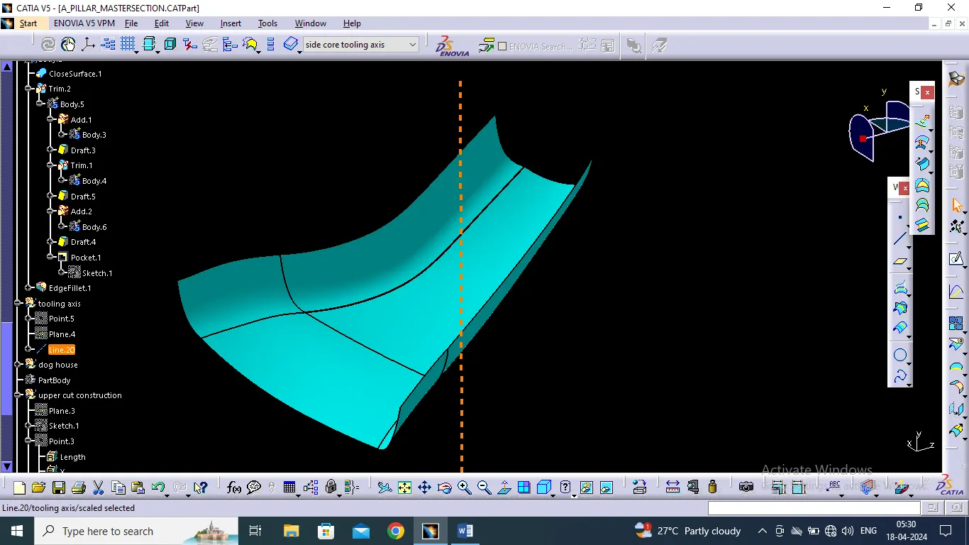
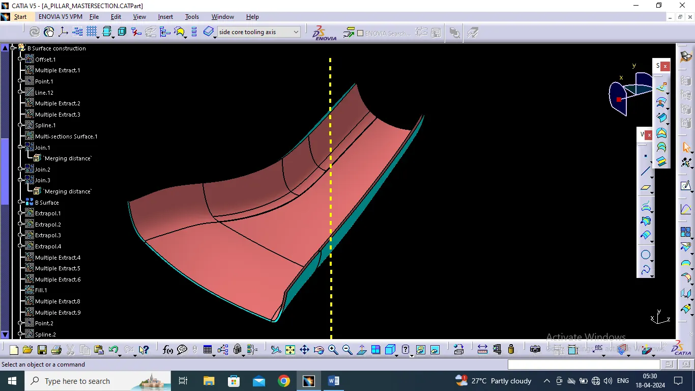
Creation of B Surface:
- Select the whole class A surface and take an offset mode by 2.5mm at inside.
- Now you can see some gaps are present in the offset surface….
- You can fill those gaps by using multi-section option, blend option or by extracting the class A Surface.
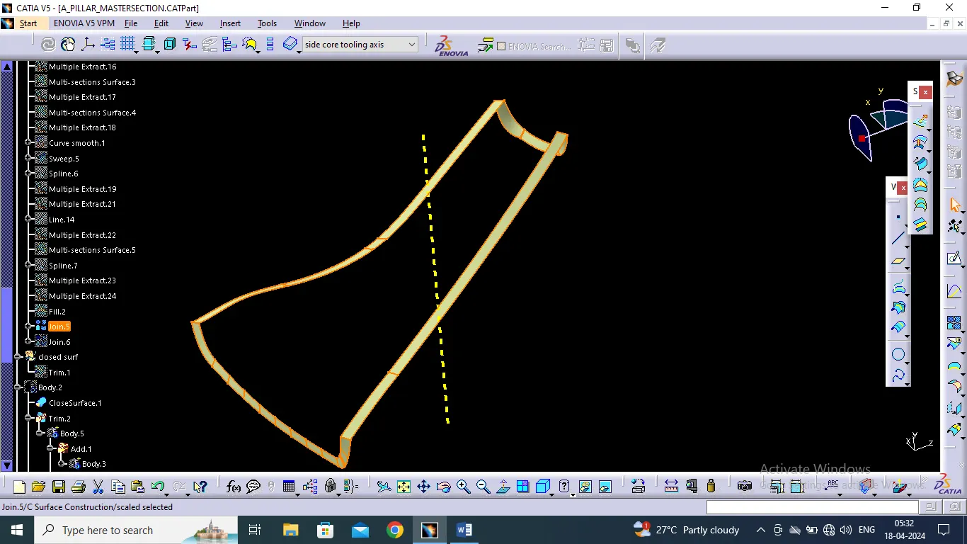
Creation of C-Surface:
- Extarct the boundary edges of class A Surface , one by one to avoid any complicated error.
- You can not allow to give direct sweep option by 90 degree in this case.
- Because in this case there are more curved surfaces are available you can not direct extrapolate that surfaces.
- So you have to take individually extrapolate that curved surfaces and flat surfaces by giving 90 degree + some draft angle.
Creation of A-C surface
Join the C-Surface and A-Surface using Join command.
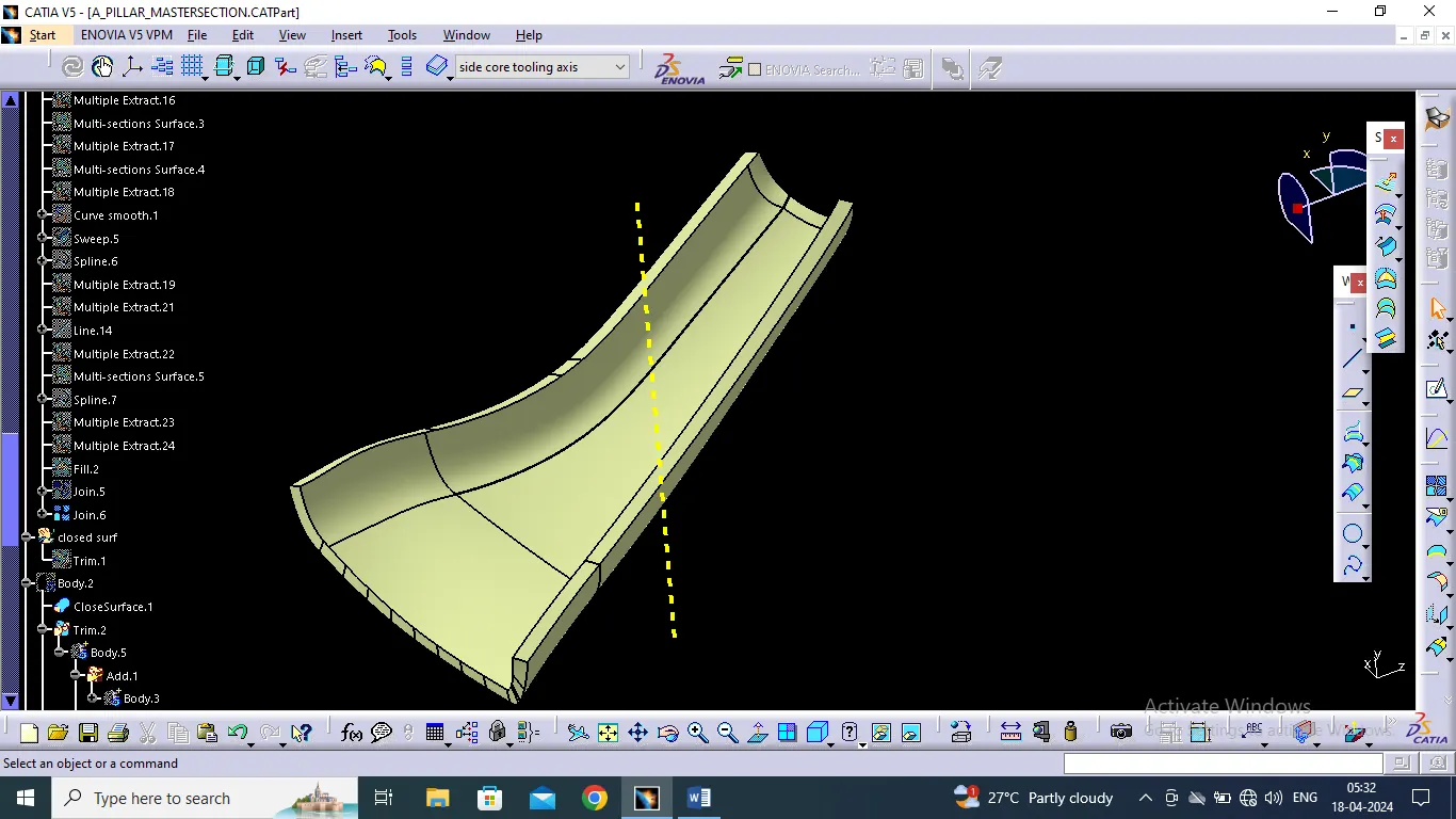
Creation of Closed Surface profile
Trim the previously generated A-C Surface by B-Surface to get the closed surface profile.
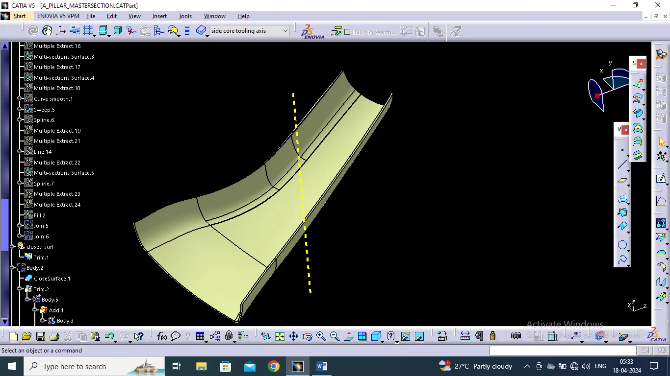
To create a solid body out of this close surface Profile , use 'CLOSE SURFACE ' command in part modelling workbench.
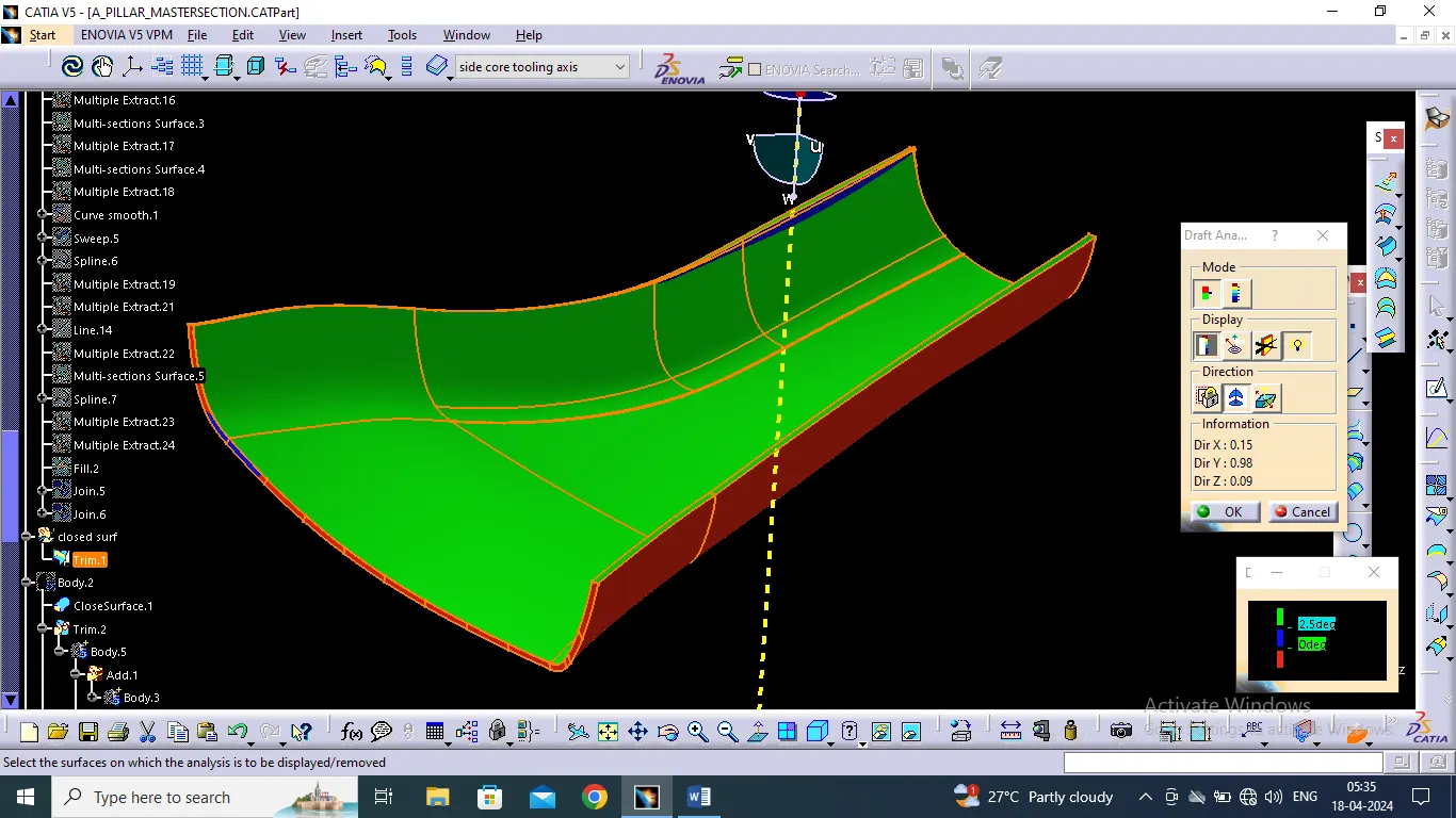
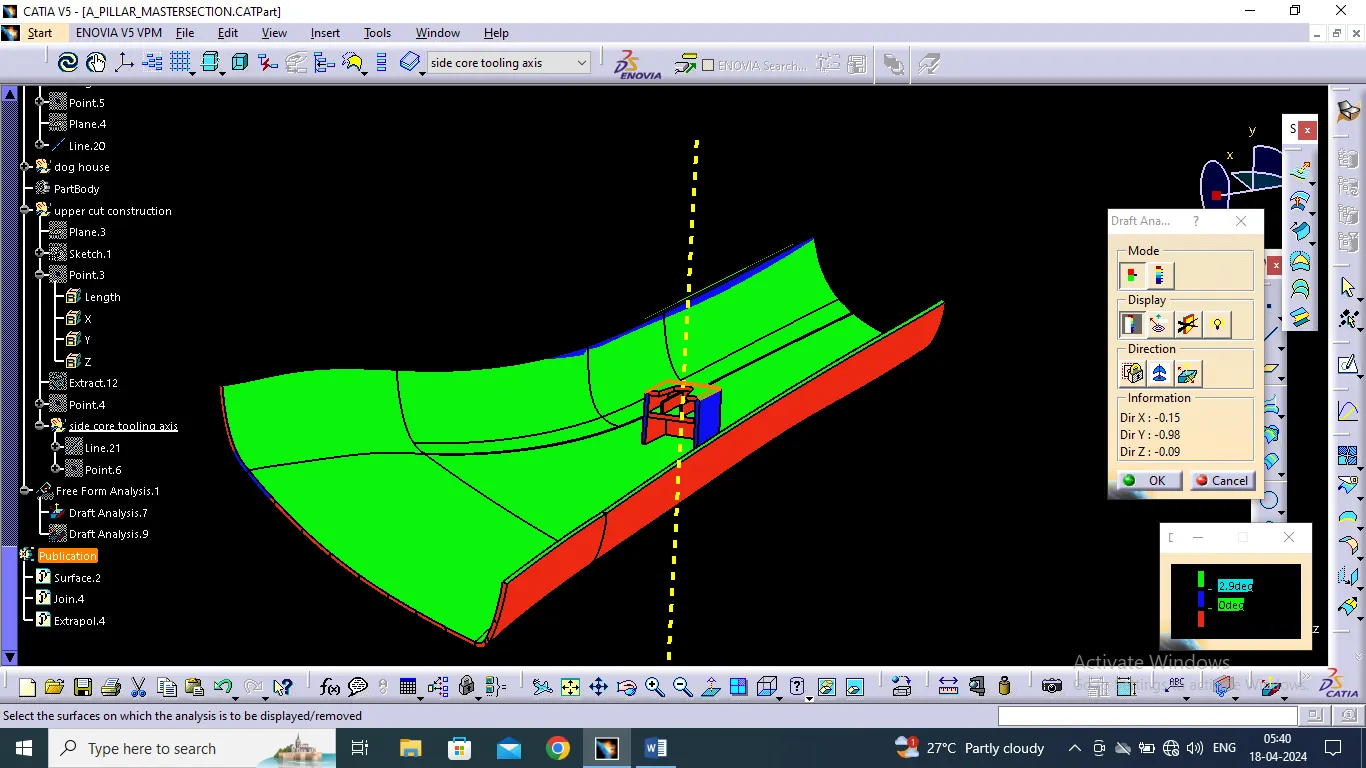
Draft Analysis
Procedure of creating draft analysis
- Go to insert menu and select the analysis option.
- Select feature and draft analysis.
- Select the material option and select the surface.
- Drag the compass and place on tooling axis.
- Make sure that the top surface is in green colour as draft angles should not exceed 3 degree.
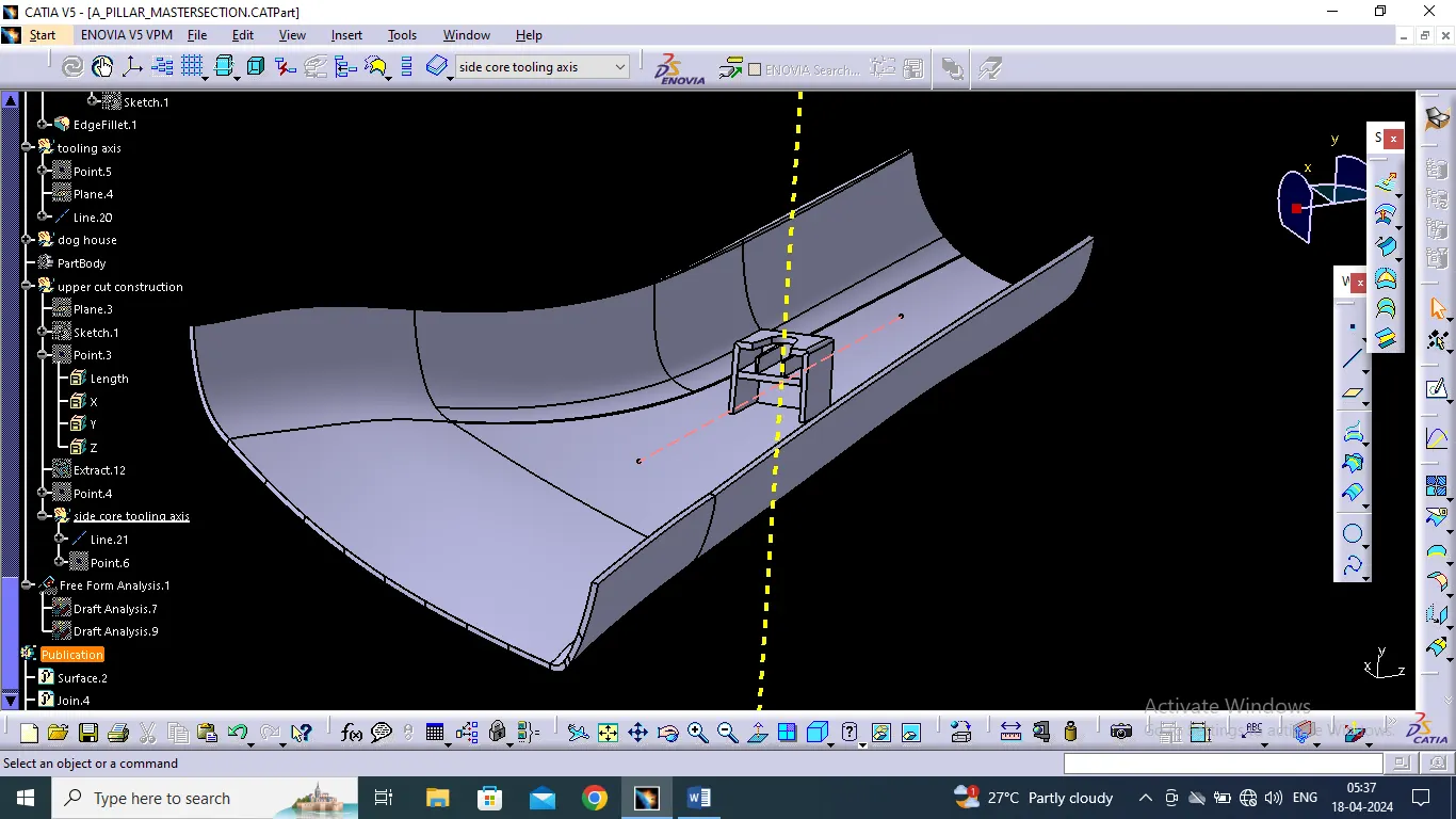
Dog House Creation according to the given master-section
- Create a Side-Core Axis for the dog house using the master section.
- Create the Dog house according to the given dimensions mentioned in the question.
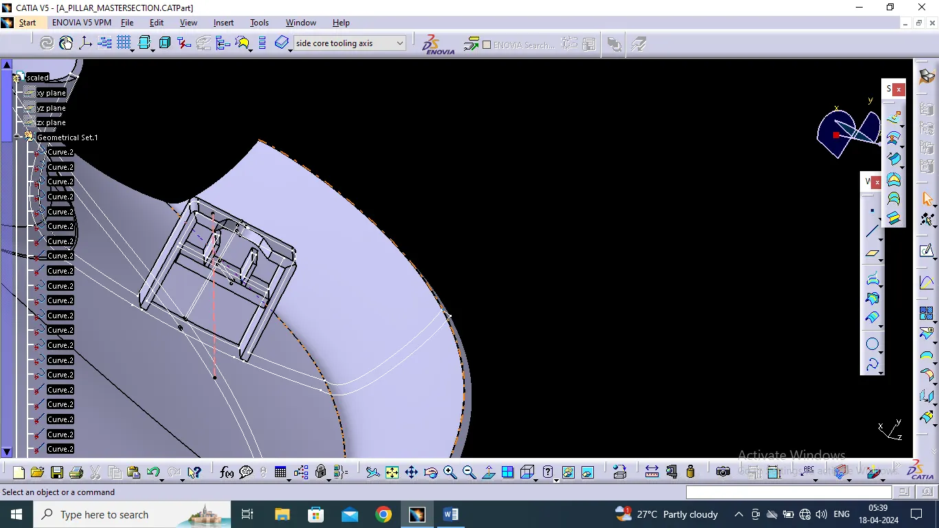
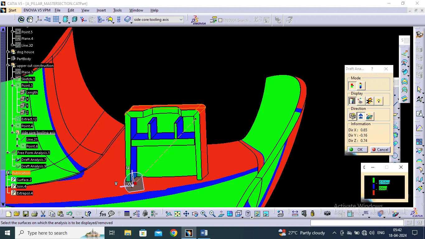
Draft Analysis for the Dog House
- Take the compass on the side core axis .
- Give minimum draft of 0.5 degrees which will show green and blue colour.
- Negative draft wil show red color.
Draft Analysis for completed part file, taking main tooling axis as reference.
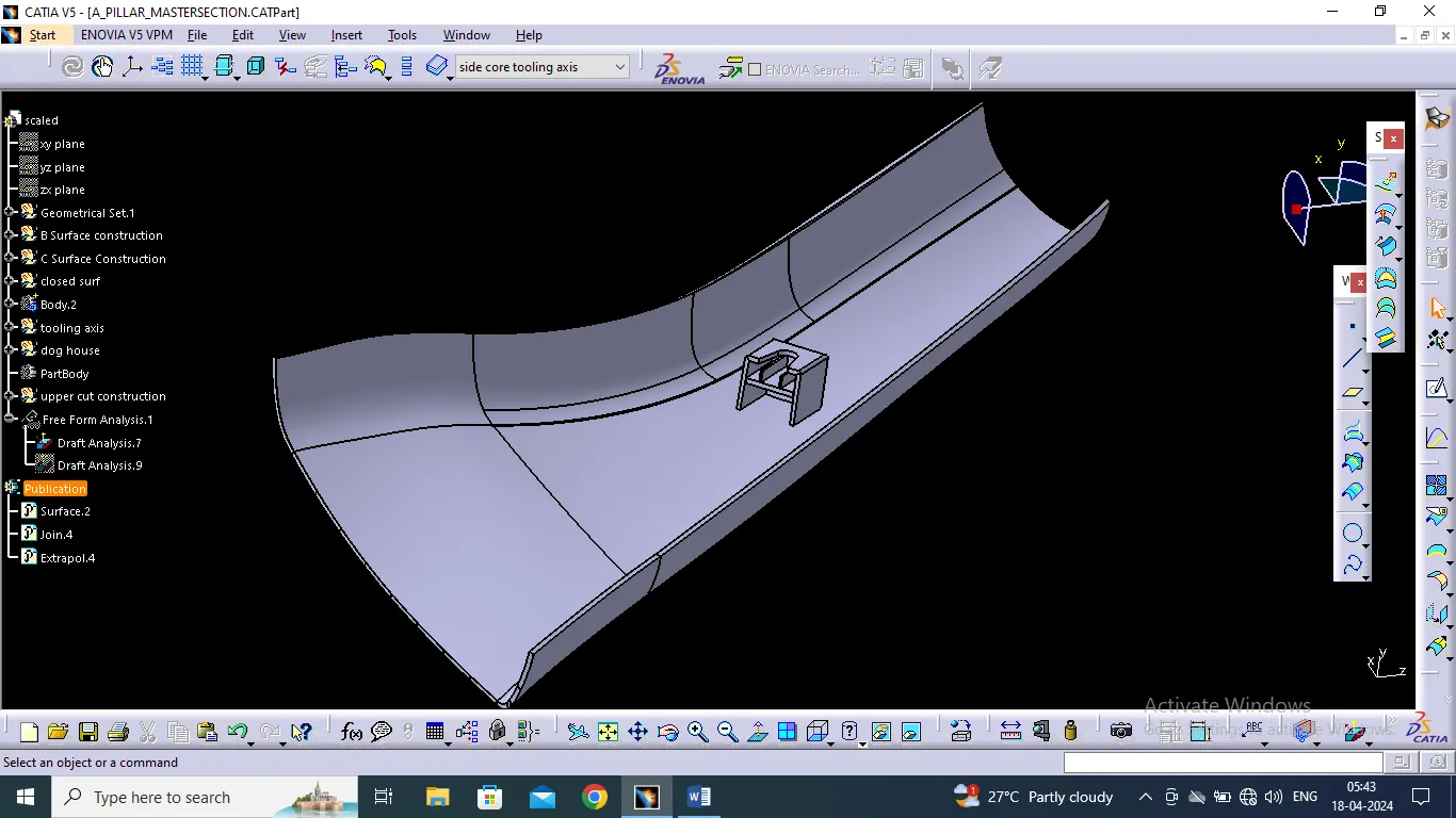
COMPLETED FULL PART BODY WITH DOG HOUSE
Below down there zip file have been attached having CAT.part file and screenshots for your reference.
Thank you.