Week 11 - Project - A pillar Design with Master Section
AIM
To Create the A-Pillar Plastic component with B Side features considering the design rules and the given master section.
THEORY
Tooling Axis
Tooling Axis is the direction in which the mold or core and cavity opens and closes. While designing a component first thing is to define the tooling axis.
Procedure
- Check the connectivity of given Class A Surface i.e no gaps between the surfaces.
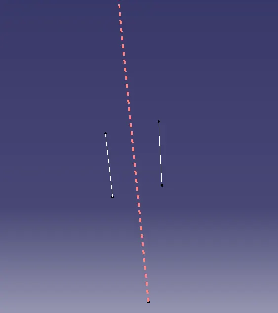
- Extract two lines on one side from the master section which we think will create problems and isolate it.
- Create a bisecting line with the lines drawn.
- Extract two lines again on one other side from the master section and isolate it.
- Create a bisecting line with the lines drawn.
- Now we have have two bisecting lines, create a bisecting line with these two bisecting lines which will give the tooling axis.
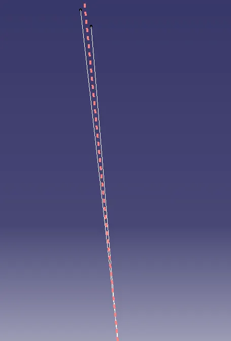
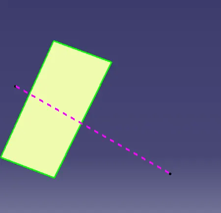
Side Core Tooling Axis
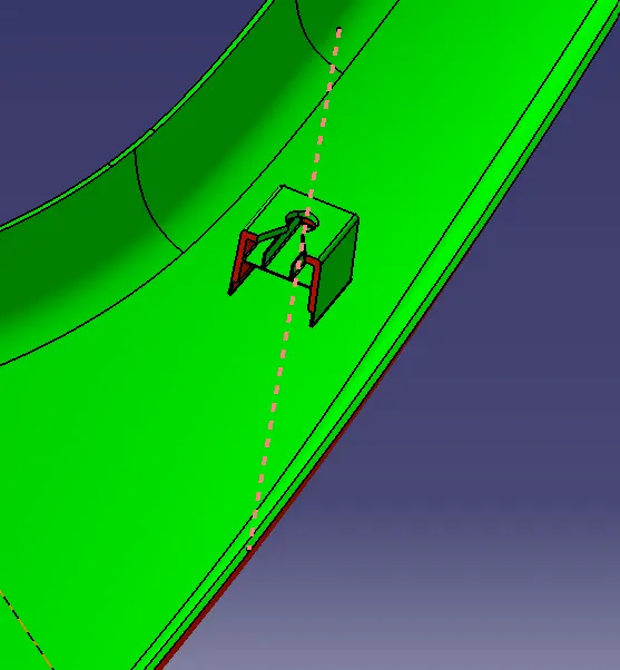
Here while creating the Dog House inside part will not clear the draft with main tooling axis so in order to clear the draft direction we will introduce tooing axis from the side which is prependicular to the face that is not clearing the draft in main tooling axis direction
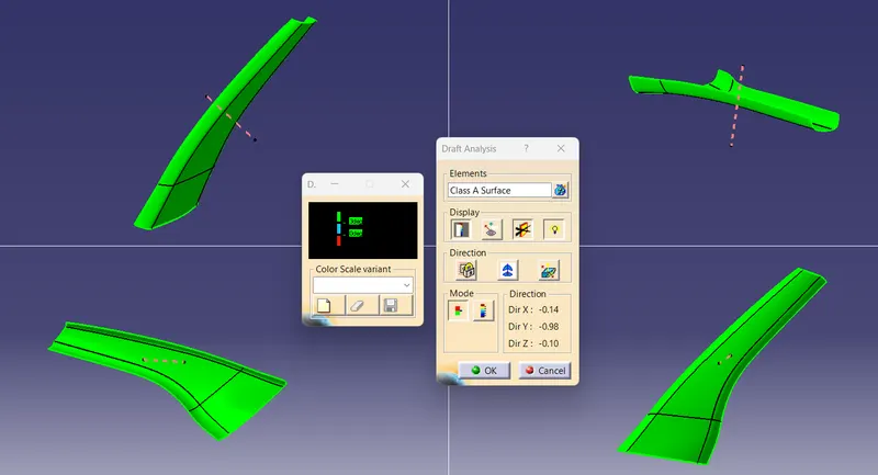
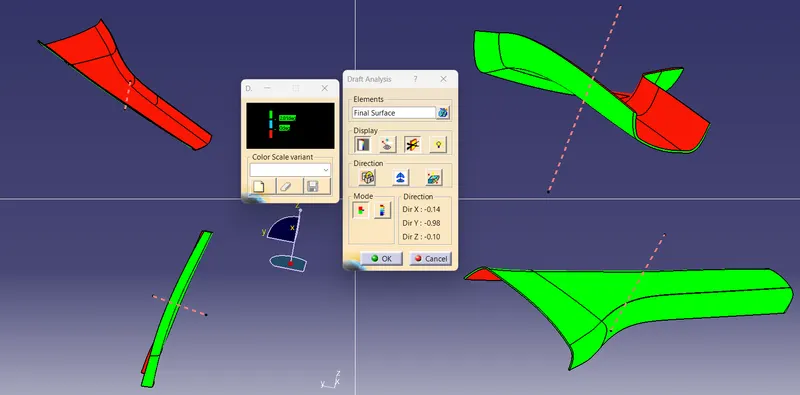
Draft Analysis
Draft analysis is used to analyze whether the part model created in CAD id manufacturable based on the draft condition applied.
Draft is required on all parts in the direction of mold movement in order to allow parts to release or eject from the mold properly. Most part or application require minimum `0.5^o - 1^o` as draft angle, however `3^o` is widely accepted as the norm.
Procedure
- First change the view to " Customize View Parameters" and select Material option.
- Select Feature Draft Analysis from the tool bar.
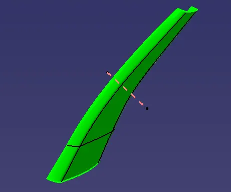
- Click on the direction, drag and drop the compass to the component such that it should coincide with the tooling axis.
- Lock the draft direction and click on the component.
- Green colour shows the positive draft, cyan as zero degree and red as negative draft
A-Pillar
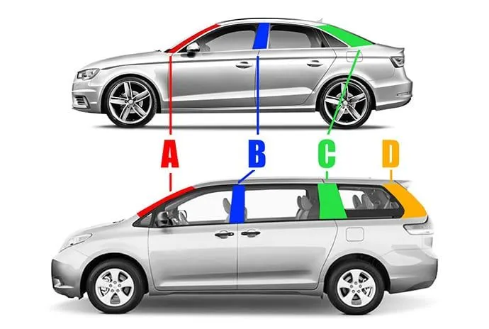
The “A” pillar of an automobile is the structure that connects the side of the body of the car with the roof of the car and to which the windshield is attached. It is the first (from the front) support for the roof and, thus, is called the “A” pillar.
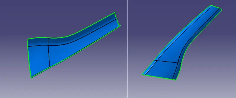
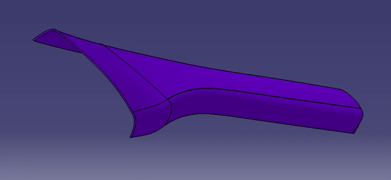
Class A Surface: Class A surface is any of a set of freeform surfaces of high efficiency and quality. In other words, Class A surface is the aesthetic surface.
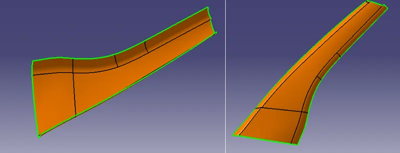
Class B Surface: Class B surface is the thickened suface or engineering surface where all ribs, screw bosses, dog houses etc will come.
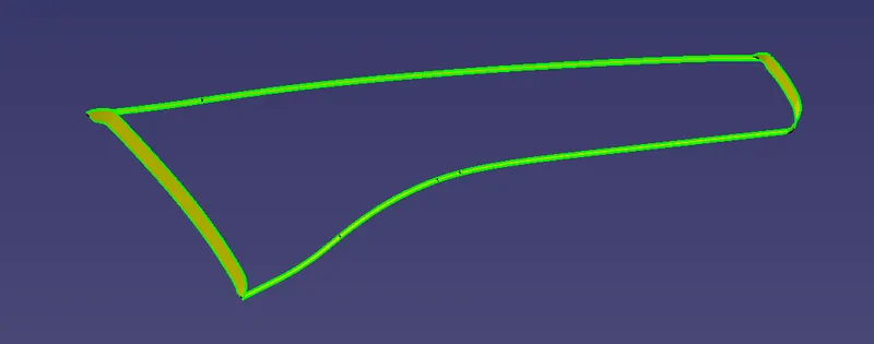
Class C Surface: It is the Surface which joins Class A and Class B surfaces.
SOFTWARE USED
Catia V5
DESIGN
Thickness T : 2.5mm
Tree Structure
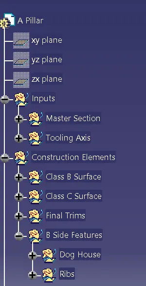
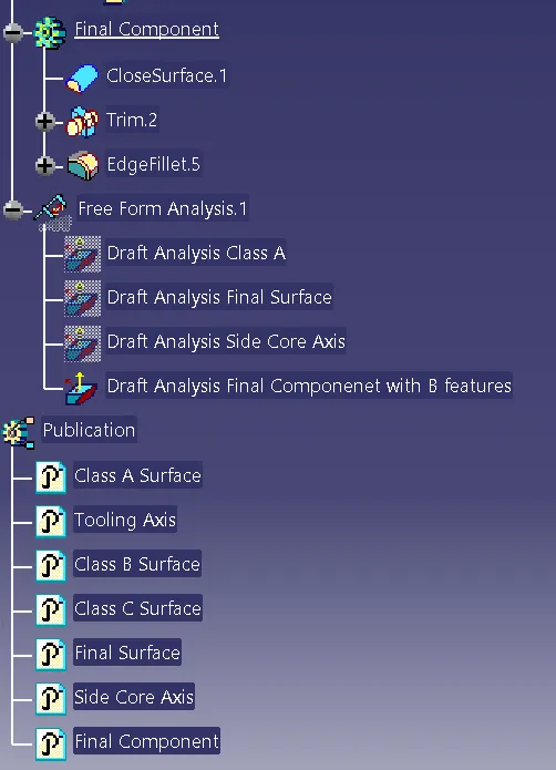
Tooling Axis
Draft Analysis
Class A Surface
Final Surface
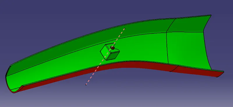
Dog House
Main Tooling Axis
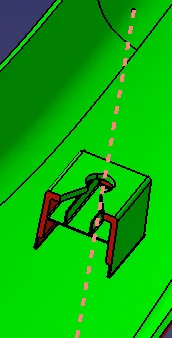
Side Core Axis
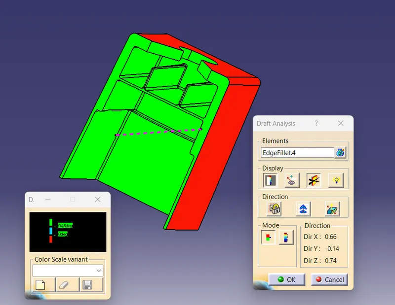
Final Solid Component
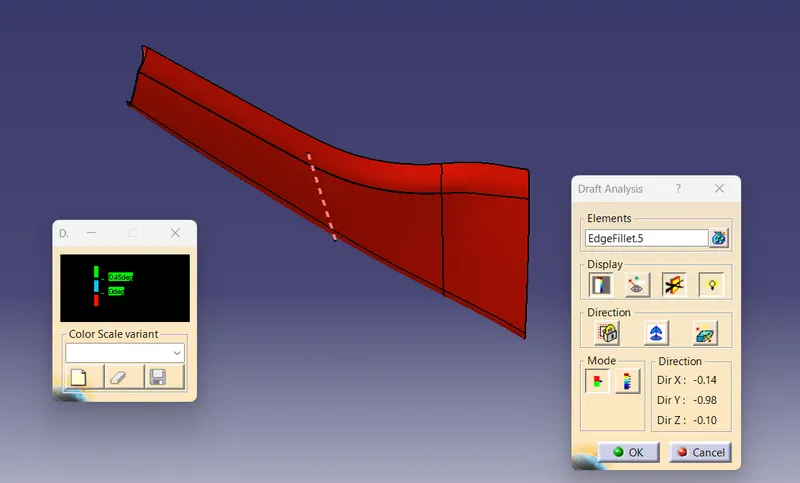
Class A Surface
Class B Surface
Class C Surface
Final Joined Surface
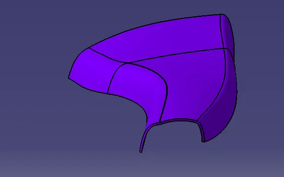
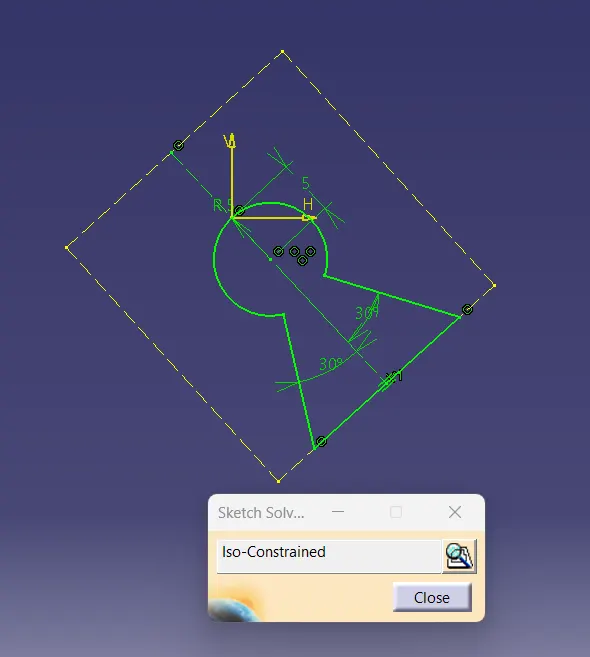
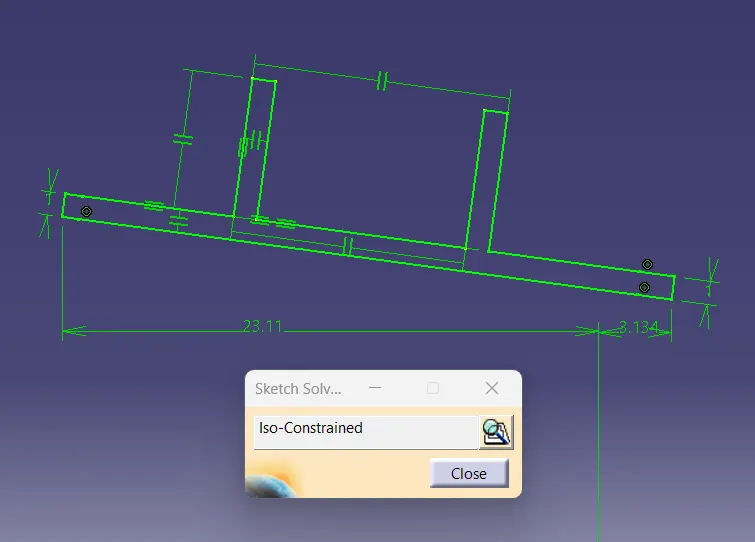
Dog House
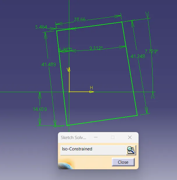
Sketch
3D Model
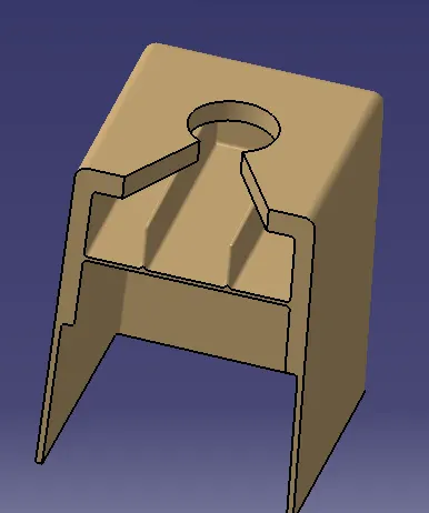
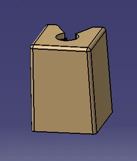
Final Component With Dog House In Various Orientations
Isometric View
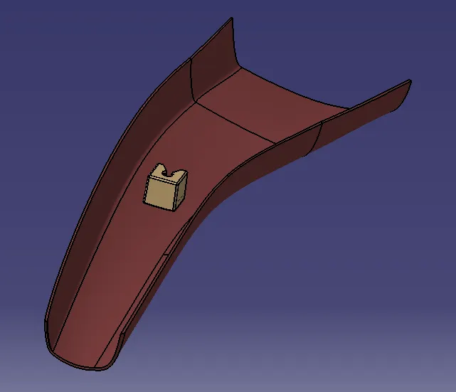
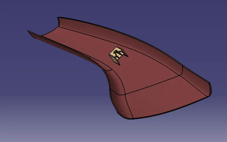
Front View
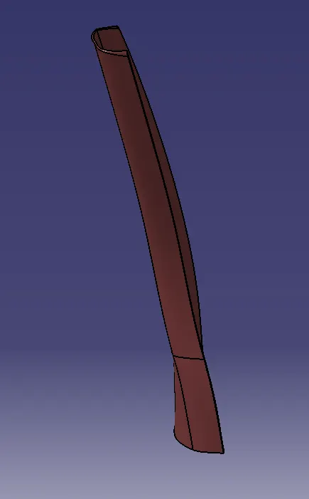
Left Side View
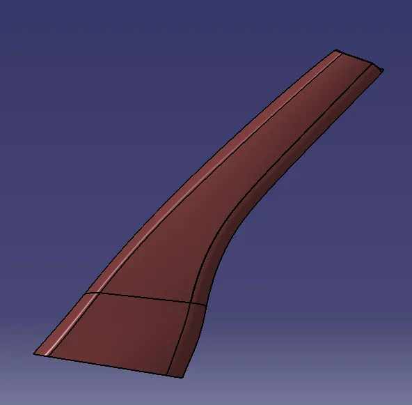
Right Side View
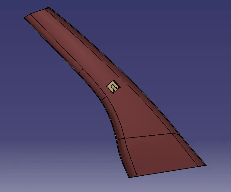
Top View
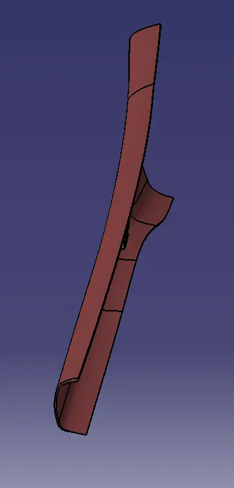
CONCLUSION
A-Pillar Plastic component with B Side features as per the given master section, considering the design rules has been created in Catia.