Week 11 - Project - A pillar Design with Master Section
AIM:
To construct the tooling axis, complete the draft analysis for the final solid component, then develop the A Pillar Design using the master section as the intersection sketch with the Class A surface.
OBJECTIVES:
- Utilizing the master section and the bisecting approach, create the necessary tooling axis.
- Create the Class-B and Class-C surfaces, then seal the three surfaces together.
- Draw the dog house's inside and adhere to the provided drafts and material section sketch.
- Draft analyses are provided for the side core and final solid portion.
INTRODUCTION:
THEORY:
- TOOLING AXIS:
To determine the tooling axis, or tooling direction, that molds pull apart during injection molding, the Class-A surface is first evaluated. Given that it determines the direction of mold separation, tooling direction is crucial to the design of plastic products.
- SURFACES(CLASS A,B, C):
- Class A Surface: Class A surfaces have the best finish quality and are aesthetically pleasing. 'Autodesk-Alias' is used to create the majority of Class A Surfaces for Automotive Components, utilizing the final Concept-Sketch. 'Curvature-Continuity' refers to the property where the boundaries of the continuity between two surfaces in a Class A surface share. To develop 'Class B' and 'Class C' Surfaces, the Automotive Plastic Designer uses it as reference.
- Class B Surface: At a specific thickness, the Class B Surface is located underneath the Class A Surface. Engineering principles are used in its creation, and it has all the required components, including snaps, bosses, and ribs. From the outside, an observer cannot see this surface.
- Class C Surface: The surface formed to connect the Class A and Class B surfaces is known as the Class C Surface.
- A-PILLAR:
A-Pillars can be found on each side of the front windshield or glass of your vehicle.Your front doors' hinges are also supported by them. Steel alloys are typically used to make A-pillars.A-pillars are not only a supporting component but also extremely important in terms of safety. Typically, in a frontal or rollover accident, the A-pillars bear a heavy weight.
- CLASS A SURFACE:
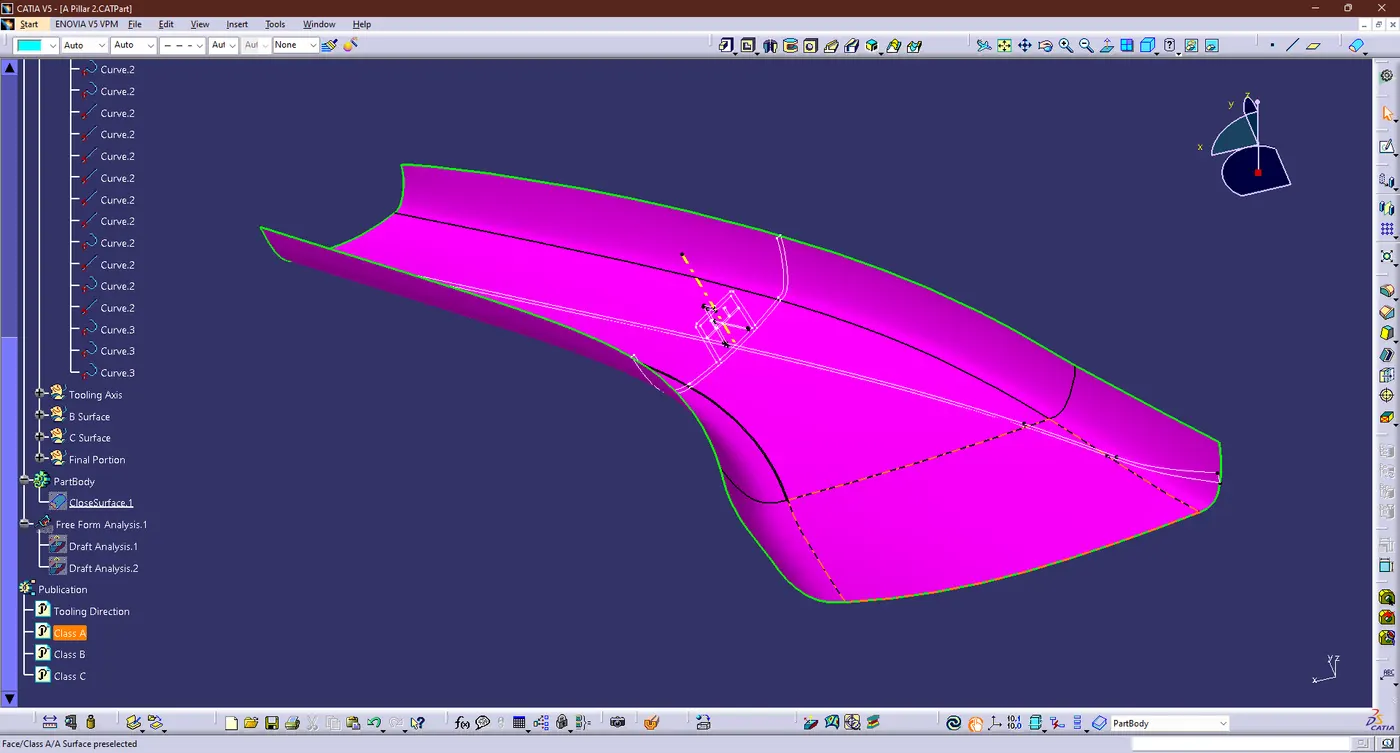
PROCEDURE FOR CREATING THE A-PILLAR:
CREATION OF TOOLING AXIS:
- We will use the Master Section by extracting the lines as indicated below and produce a Bisecting Line with regard to those extracted lines to create our Main because we have been given a Master Section to employ in order to create the needed A-Pillar Plastic Component.
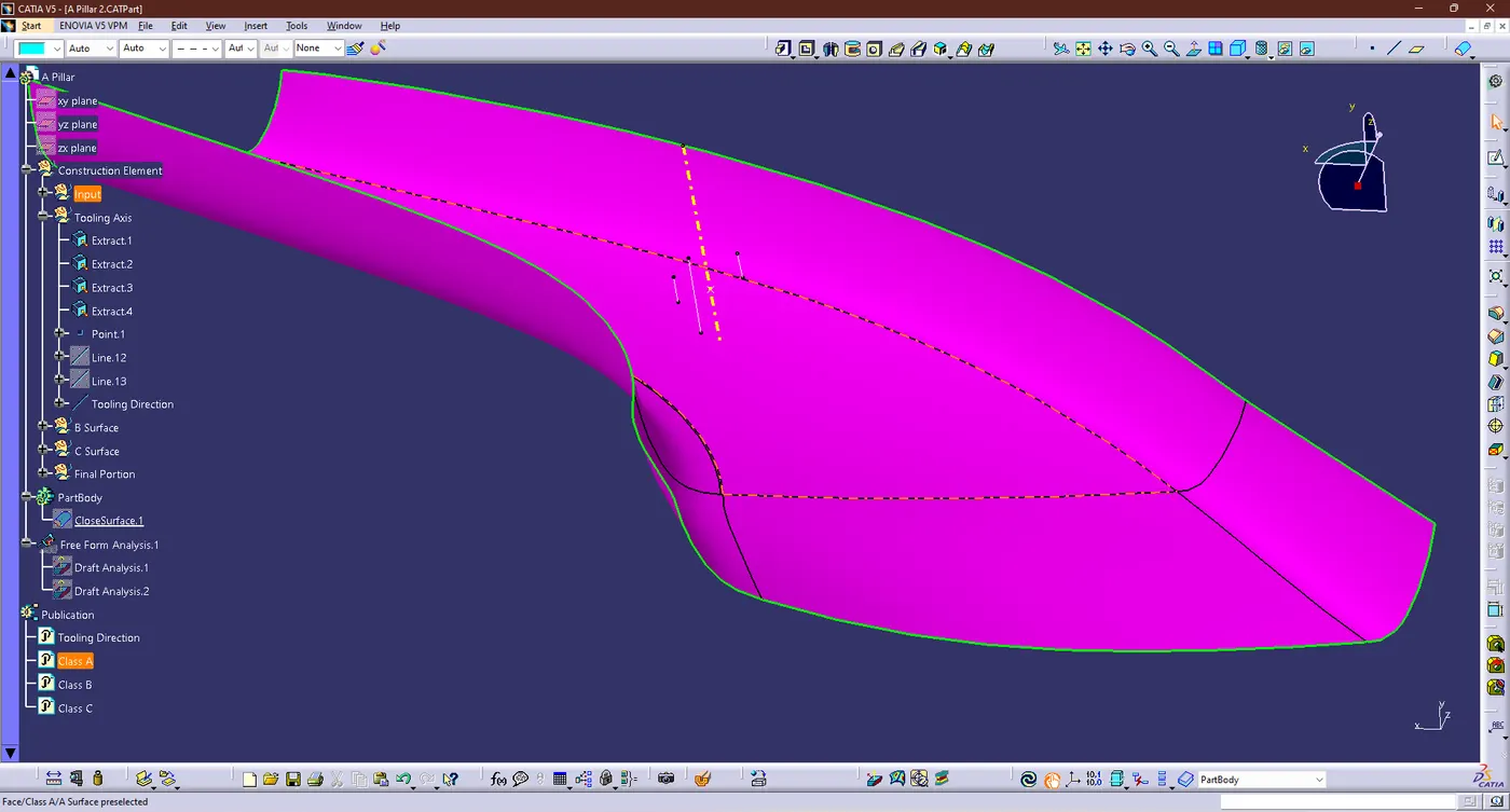
DRAFT ANALAYSIS FOR CLASS A:
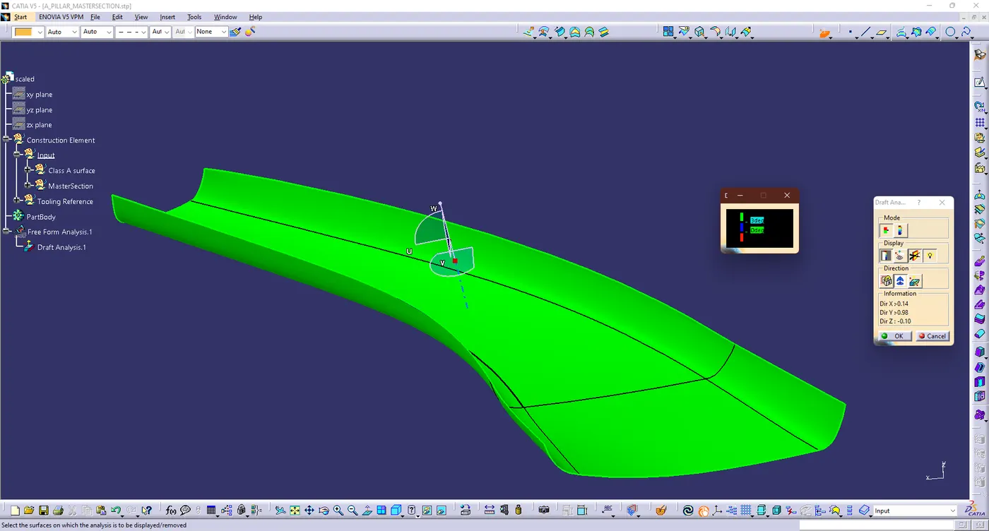
- We perform a draft analysis check for the Class A surface before we make solid part and creating features on Class B surfaces.
- Initially, I aligned the compass with the Tooling Axid and gave a Draft angle of 3 degrees for the green coluor on the Class A surface.
CREATION OF B SURFACE:
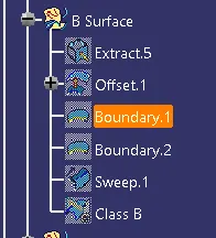
- First we need do offset from the class A surface with thickness of 2.5mm as given with the master section
- The Class A Surface's complex curvature prevents it from offsetting properly, therefore we have to utilize tools like Sweep Command to rebuild the missing patch.To utilize the sweep command on it, we'll set up two borders as indicated below:
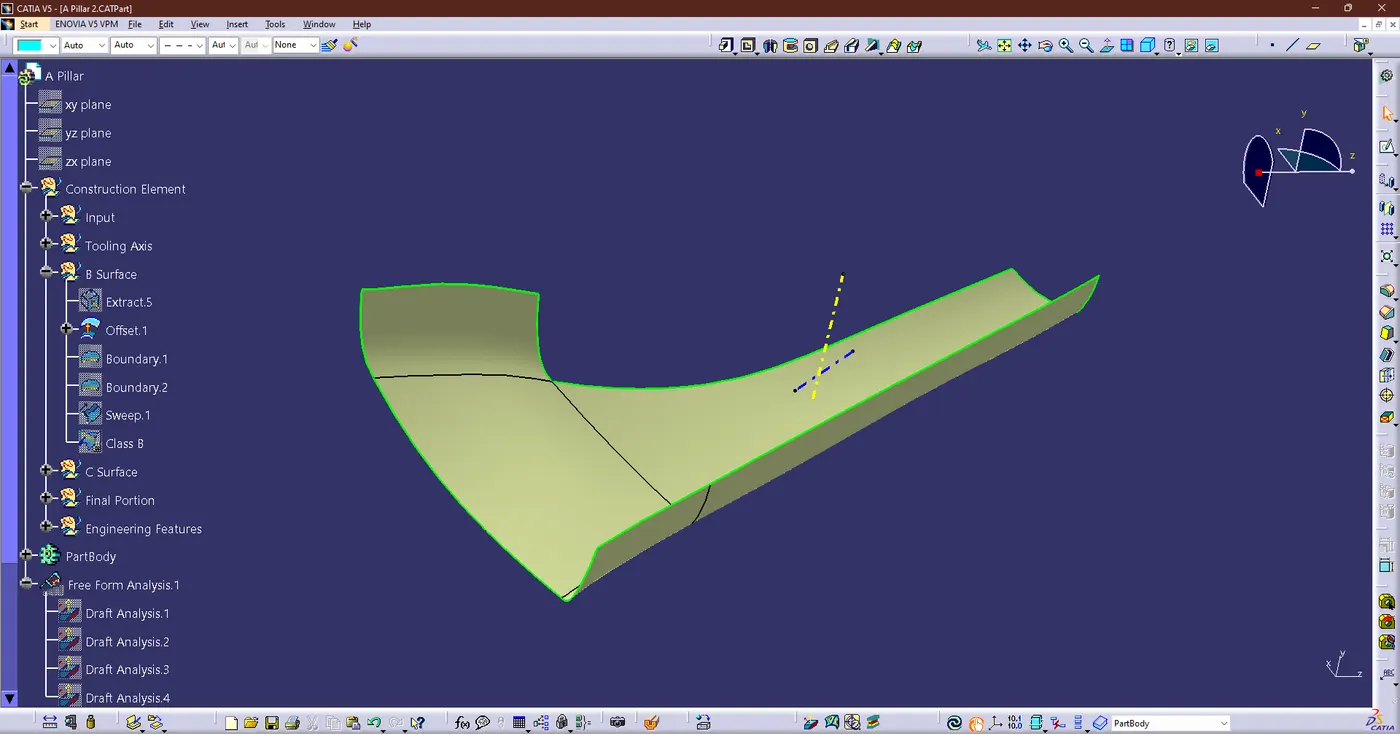
- Next, we'll use the primary offset that we took fro the class A surface to link the jusr formed surface.
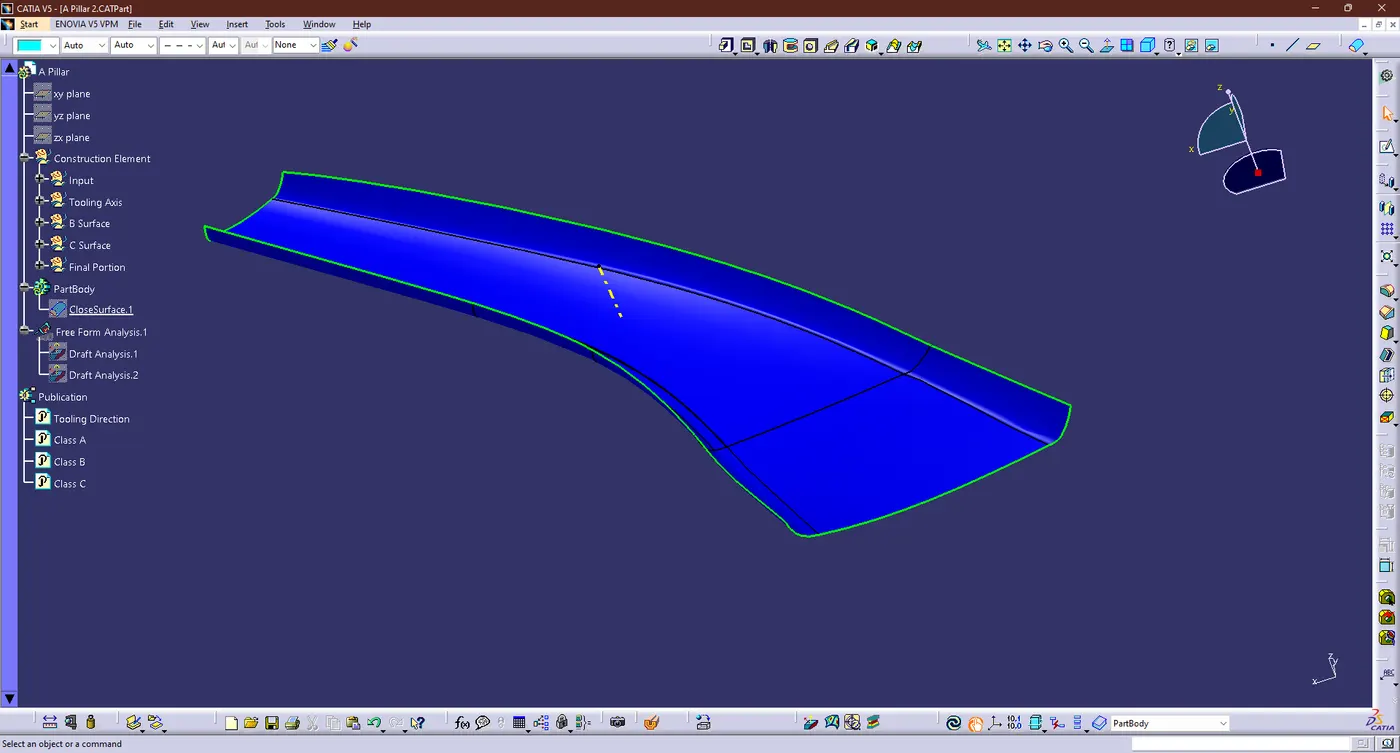
CREATION OF C SURFACE:
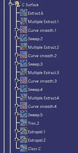
- The Class A Surface must first be unhidden in order to extract its borders
- 'Curve Smooth' will be used to smooth these extracted boundaries. Next we will generate the Class C Surface by using the 'Sweep' command with 'Reference Surface' & 'With Draft Direction':

FINAL PORTION:
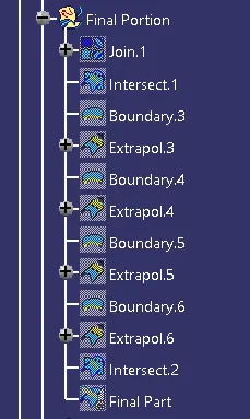
- First join the Class A & C Surfaces, using the join Command , Then trim with Class B Surface using the Trim Command
- Now we got the hollow part body of the A pillar.
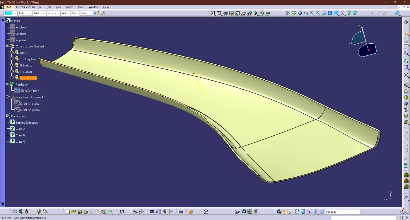
SOLID BODY:
- The hollow is then created as a solid by selecting the Body option and then selecting the Close body option and hence we got the final output were mention below
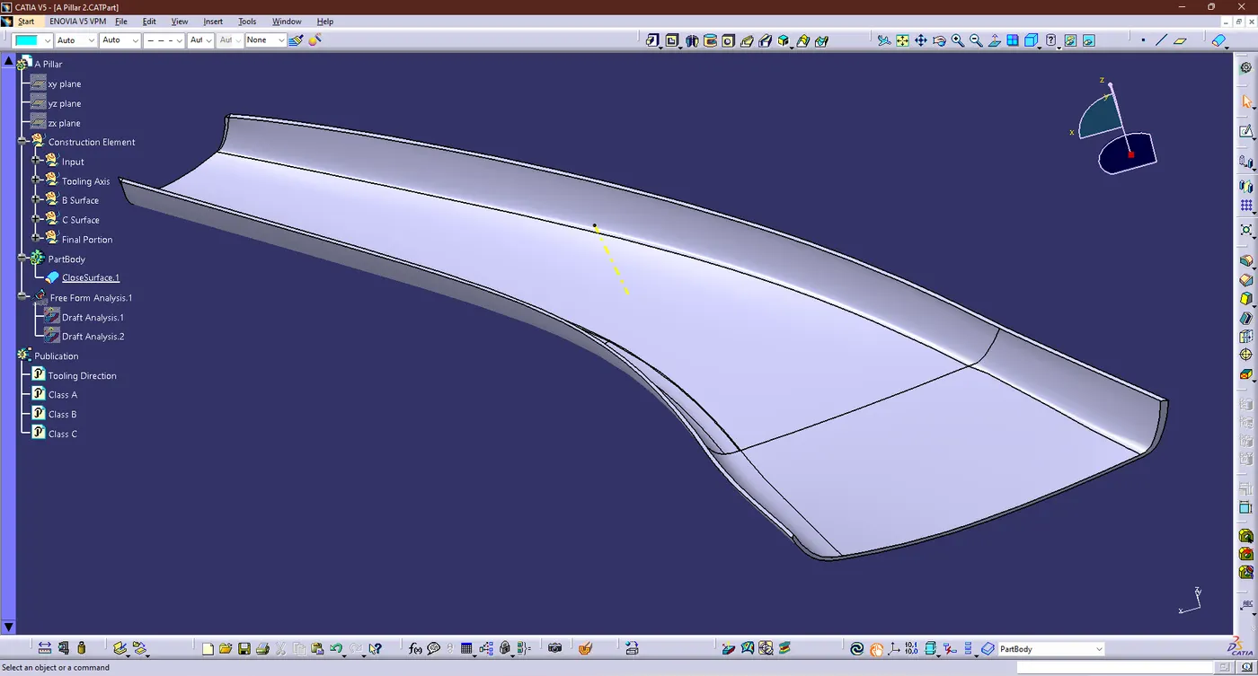
:
- CREATION OF DOG HOUSE:
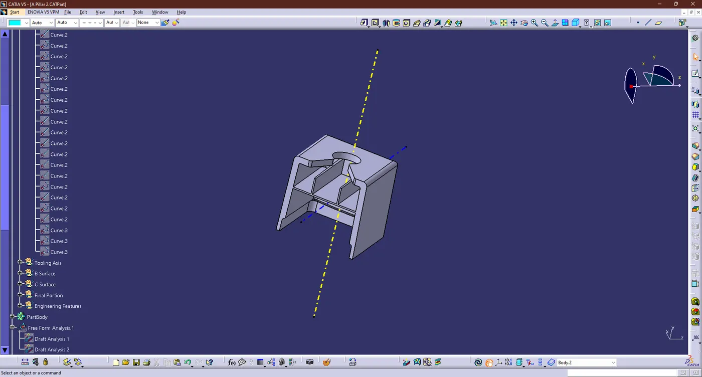
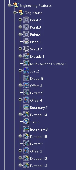
- We may draw a design in the Master Section that will allow the walls of the doghouse to be extruded using the Extrude command.
- Then given the thickness has 2.5mm for the dog house sketch After that, we're going to provide all the required drafts using the Draft command.
- Regarding the Main Tooling axis and Side-Core axis, respectively, Draft Angle is given at the doghouse's outside and inner portions.
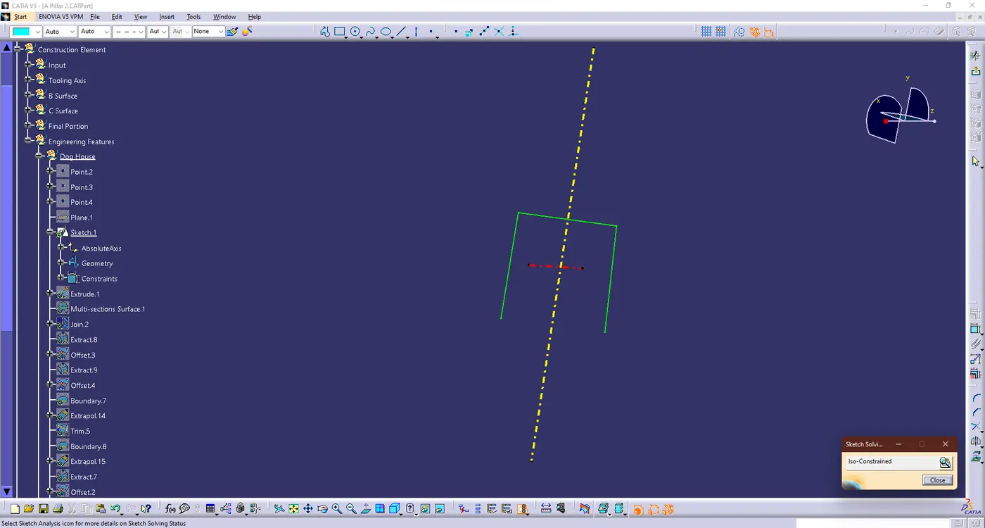
- CREATION OF RIB :
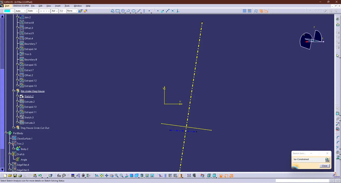
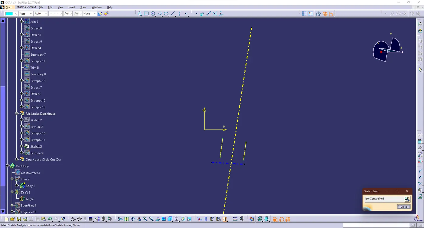
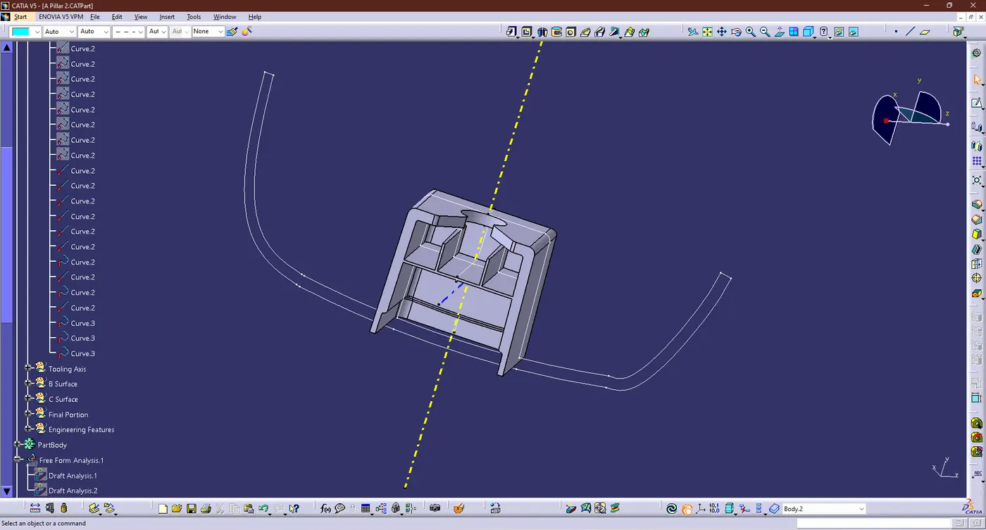
- We may draw a design in the Master Section that will allow the walls of the RIB under the dog house to be extruded using the Extrude command.
- Then given the thickness in Master section for the RIB has 1mm for the RIB sketch 1&2 After that, we're going to provide all the required drafts using the Draft command.
- Regarding the Side-Core axis, respectively, Draft Angle is given at the RIB under the doghouse portions.
DRAFT ANALYSIS:
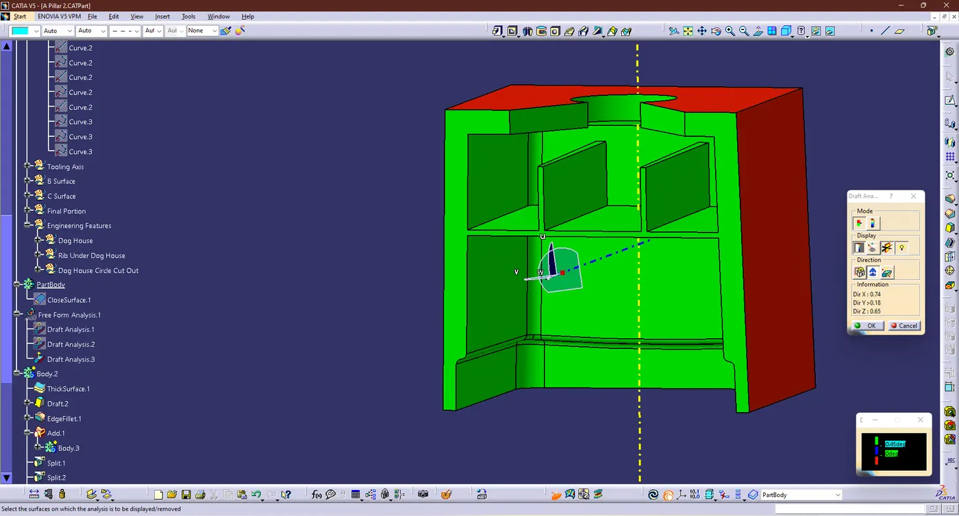
- DRAFT ANALYSIS FOR THE DOG HOUSE:
- In Plastic Design, the draft analysis or angle that is considered in the OEMs is 3 degree.
- Same thing were do follow for the draft analysis on earlier and output mention below
- Then we got degree has 0.45 deg
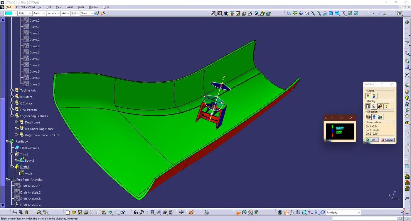
- DRAFT ANALYSIS FOR THE FINAL PART BODY:
- In Plastic Design, the draft analysis or angle that is considered in the OEMs is 3 degree.
- Same thing were do follow for the draft analysis on earlier and output mention below
- Then we got degree has 2.5 deg \
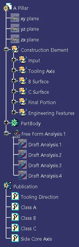
TREE STRUCTURE:
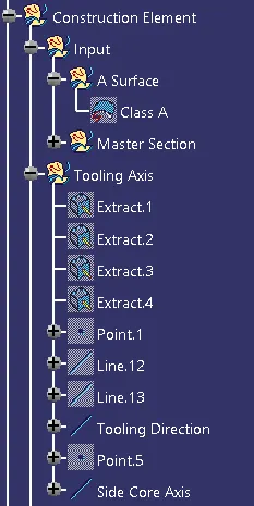
- Input & Tooling Axis:
- B Surface:
- C Surface:
- Final Portion:
- Engineering Features (Dog House):
- Engineering Features (RIB):
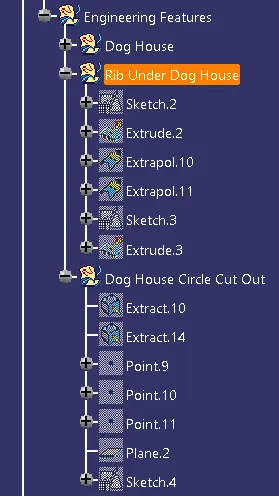
- Part Body:
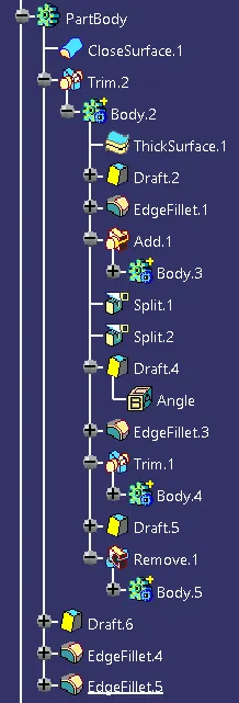
- Draft Analysis & Publications:
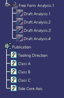
CONCLUSION:
As a result, the A Pillar Design is completed successfully, along with the creation of the tooling axis and the draft analysis for the final solid component. The master section is provided as the intersection drawing with the Class A surface. We must advise the team responsible for building the Class-A surface that certain places in the draft analysis for that surface have a minimum draft angle of 2.5 degrees, and we must rectify this on the Class-A surface itself. Hereby i attach the CATPart file in the Browse option with all the Images alsoin the name of "Week 11 Project 1 (A Pillar).zip" file.