Week 11 - Project - A pillar Design with Master Section
AIM:
To construct the tooling axis, complete the draught analysis for the final solid part, then develop the A Pillar Design using the master section as the intersection sketch with the Class A surface.
Prior to performing the Draft-Analysis Operation on the actual Class A Surface, we must first generate the requisite Tooling-Axis for the specified Class A Surface while adhering to the relevant Draught Angle criteria.
Next, in order to construct the final plastic component and conduct draught analysis on it, we must produce the necessary Class B and Class C surfaces.
PROCEDURE TO CREATE THE MAIN TOOLING AXIS:
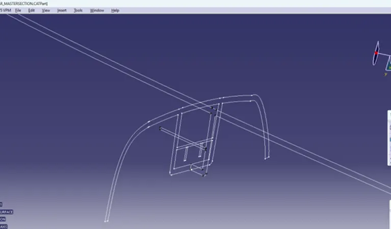
We will use the Master Section by extracting the lines as indicated below and produce a bisecting line with respect to those extracted lines to establish our Main Tooling Axis, as we have been given a Master Section to use in order to create the needed A-Pillar Plastic Component.
SURFACE CLASS A:
Class A surfaces have the best finish quality and are aesthetically pleasing. AUTODESK ALIAS is used to create the majority of Class A Surfaces for automotive components. The Automotive Plastic Designer uses it as a guide to design CLASS B and CLASS C surfaces.
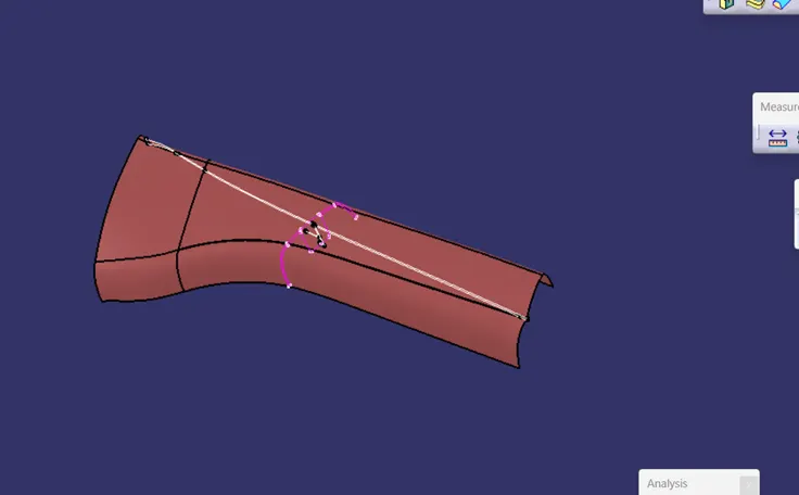
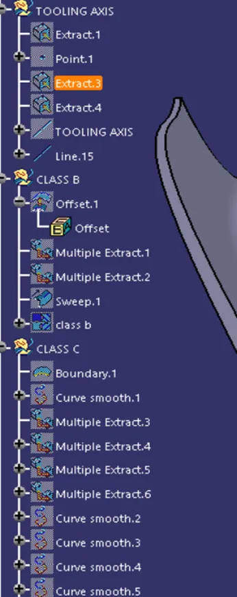
Class B Surface: At a specific thickness, the Class B Surface is located beneath the Class A Surface. Engineering principles are used in its creation, and it has all the required components, including snaps, bosses, and ribs. From the outside, an observer cannot see this surface.
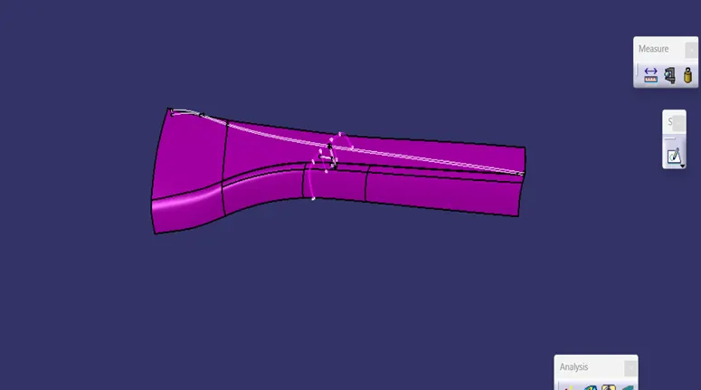
Class C Surface: The surface formed to connect the Class A and Class B surfaces is known as the Class C Surface.
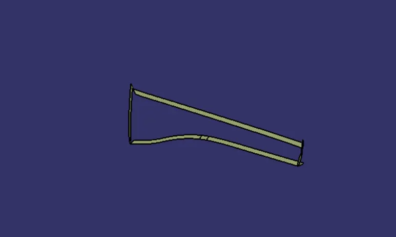
FINAL DRAFT ANALYIS:
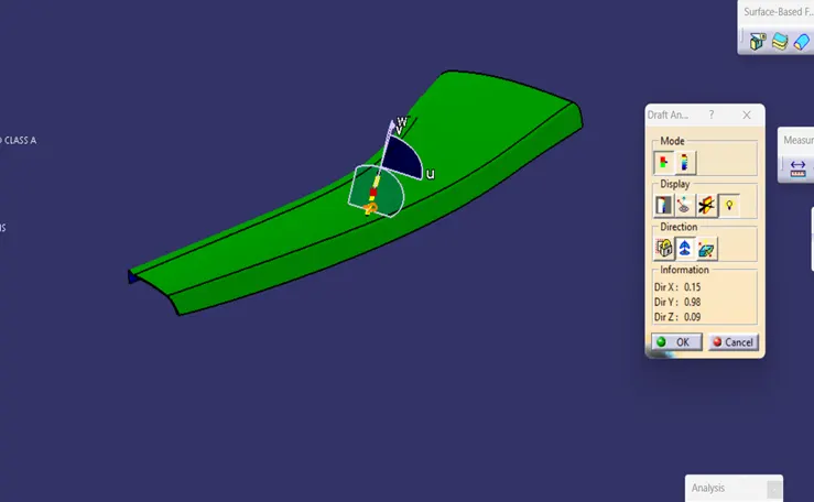
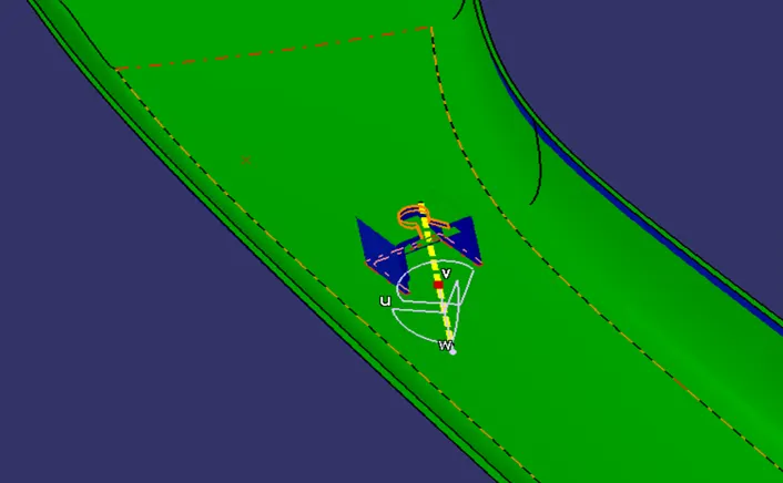
DRAFT ANALYSIS USING SIDE CORE AXIS: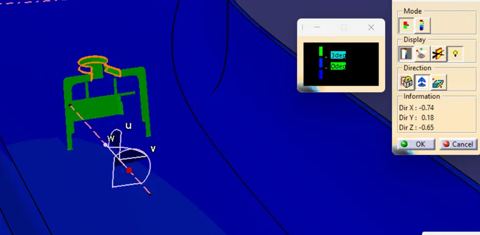
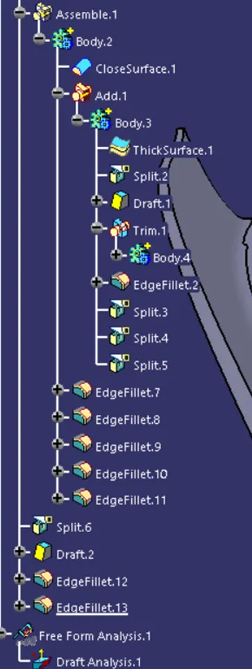
TREE STRUCTURE: