Week 11 - Project - A pillar Design with Master Section
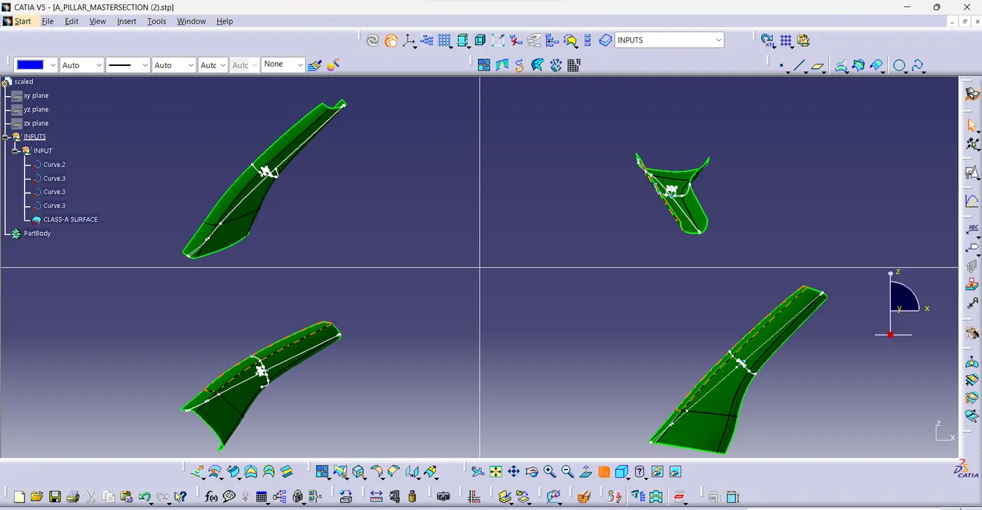
MULTISECTION(SCALED): To create a "A- PILLAR" plastic component from the given CLASS-A SURFACE using the MULTI SECTIONS by following the given design rules.
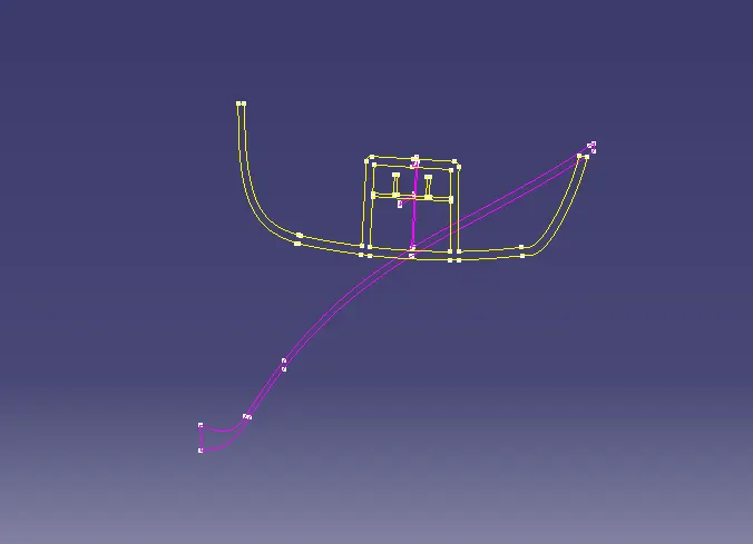
given MULTI SECTIONS,
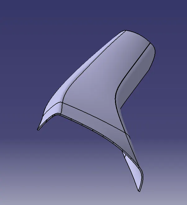
CLASS-A SURFACE: Now to check the state of connectivity and inspect the CLASS-A SURFACE for any missing patches. I used BOUNDARY command on the CLASS-A SURFACE and checked the boundary lines of the surface and the surface has no missing patch, so it is ready to be do the CLASS-B&C SURFACE.
given CLASS-A SURFACE,
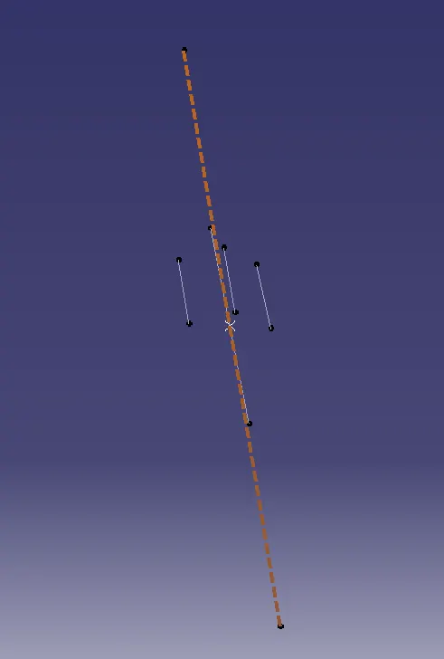
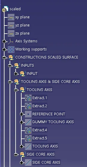
Using the MULTISECTION B- SIDE FEATURE i created a tooling axis by extracting two lines and BISECTING them to get a bisected line and i made it has a MAIN TOOLING AXIS and created a SIDE CORE AXIS also.
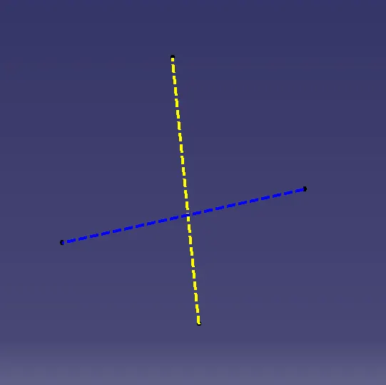
Now for the DRAFT ANALYSIS for the CLASS-A SURFACE in the minimum value of 3deg and got cleared.
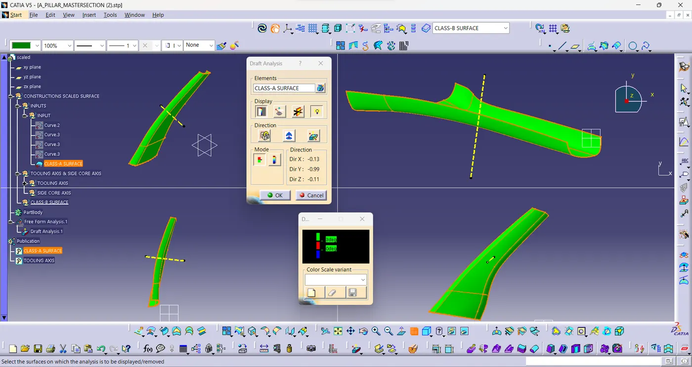
GEOMENTRICAL SET FOR CLASS-A SURFACE, SIDE CORE AXIS & TOOLING AXIS,
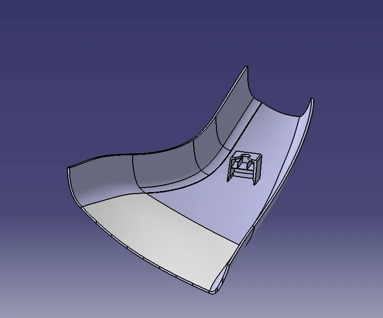
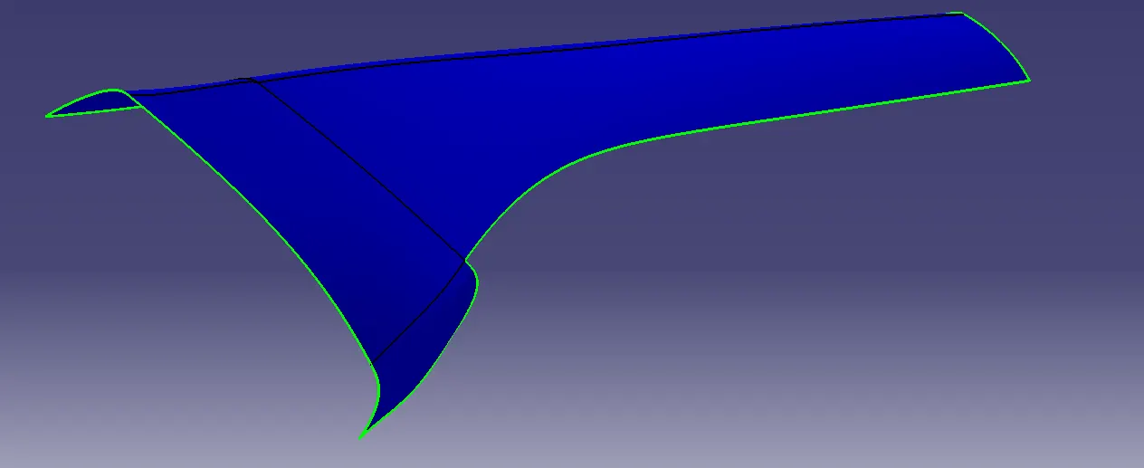
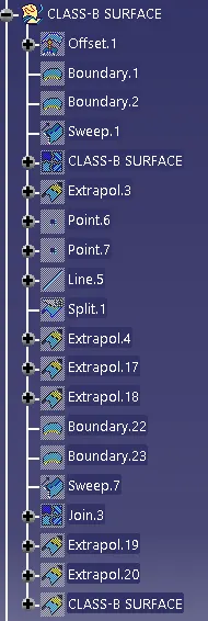
CLASS-B SURFACE: Now using the measuring tool i taken the dimension for the thickness of plactic component in the MULTI SECTION. The thickness of the plastic component is 2.5mm. Now offseting the given CLASS-A SURFACE for 2.5mm. After offset of the given CLASS-A SURFACE there is a issue of a missing patch because of the complexity of the CLASS-A SURFACE.
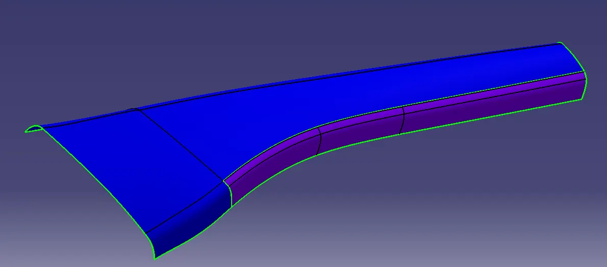
For the missing patch i created a boundary using the BOUNDARY command in the edges of the missing patch. Now using the SWEEP command i am gonna sweep the area in the missing patch by (Profile Type: EXPLICT) (Sub Type:WITH REFERENCE SURFACE) and selecting the boundarys to have the missing patch.
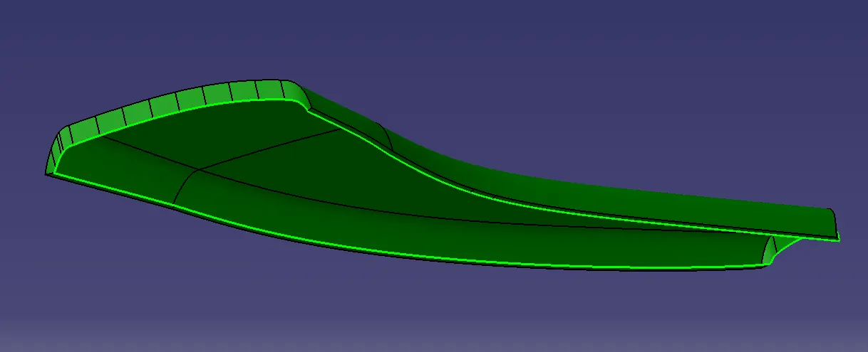
Now using the JOIN command i joined the two surfaces and thus, creating the CLASS-B SURFACE. And extrapolaited them using EXTRAPOLATE command for the final trim.
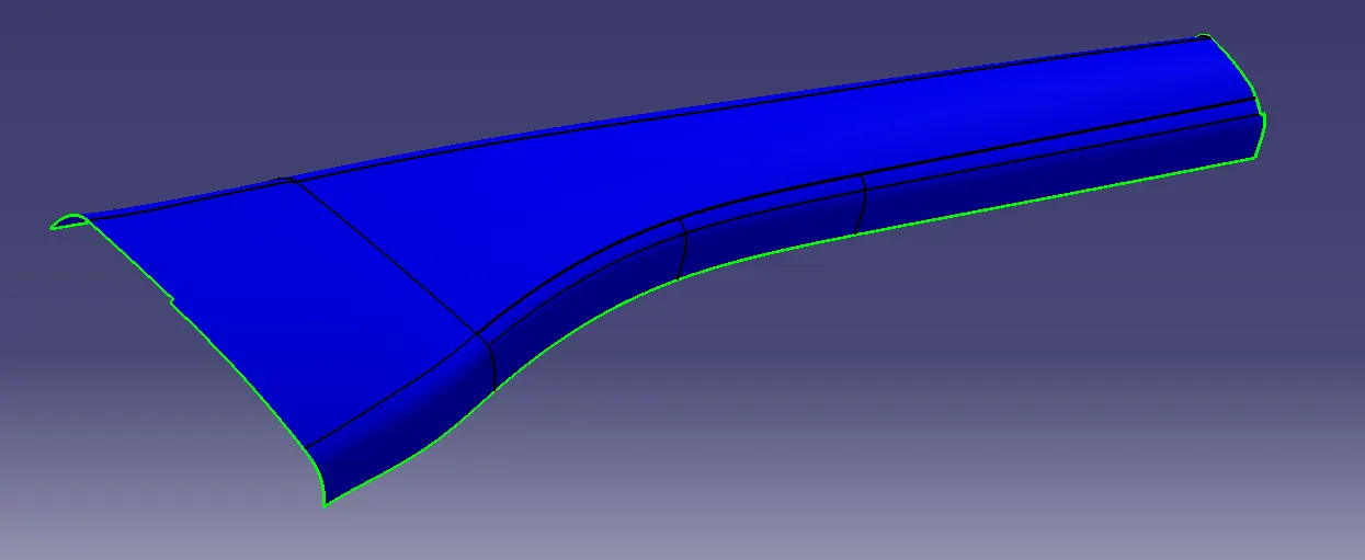
GEOMENTRICAL SET FOR CLASS-B SURFACE,
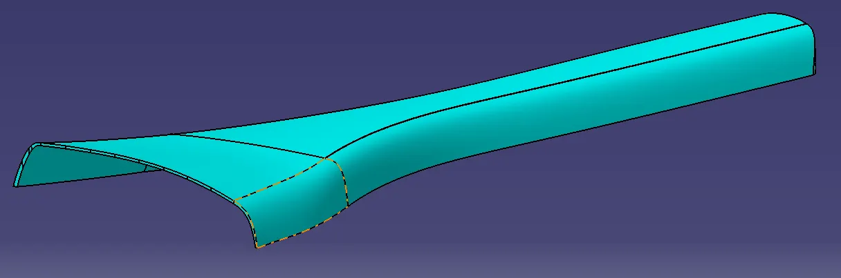
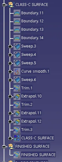
CLASS-C SURFACE & FINISHED SURFACE: To create the CLASS-C SURFACE we have to unhide the CLASS-A SURFACE and work on the surface by creating a boundary and using SWEEP command to foarm a CLASS-C SURFACE. Now unhiding the CLASS-B SURFACE and using JOIN command joining the both CLASS-B&C SURFACE and achieving the finished surface.
CLASS-C SURFACE,
FINISHED SURFACE,
GEOMENTRICAL SET FOR CLASS-C SURFACE & FINISHED SURFACE,
FINISHED CLOSED SURFACE & DRAFT ANALYSIS FOR THE CLOSED BODY:
Now going to the PART WORKBENCH i created a closed surface for the FINSHED SURFACE and done the DRAFT ANALYSIS for the closed surface and it is clearing in 3deg.
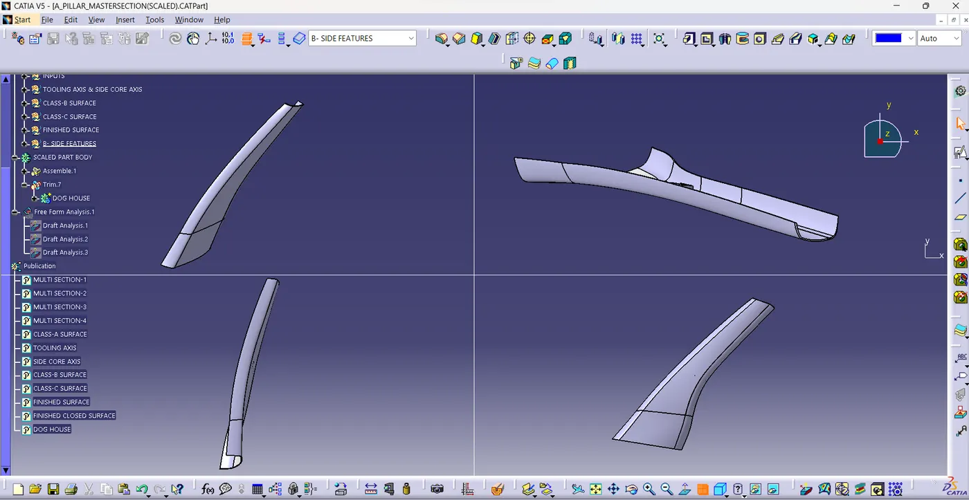
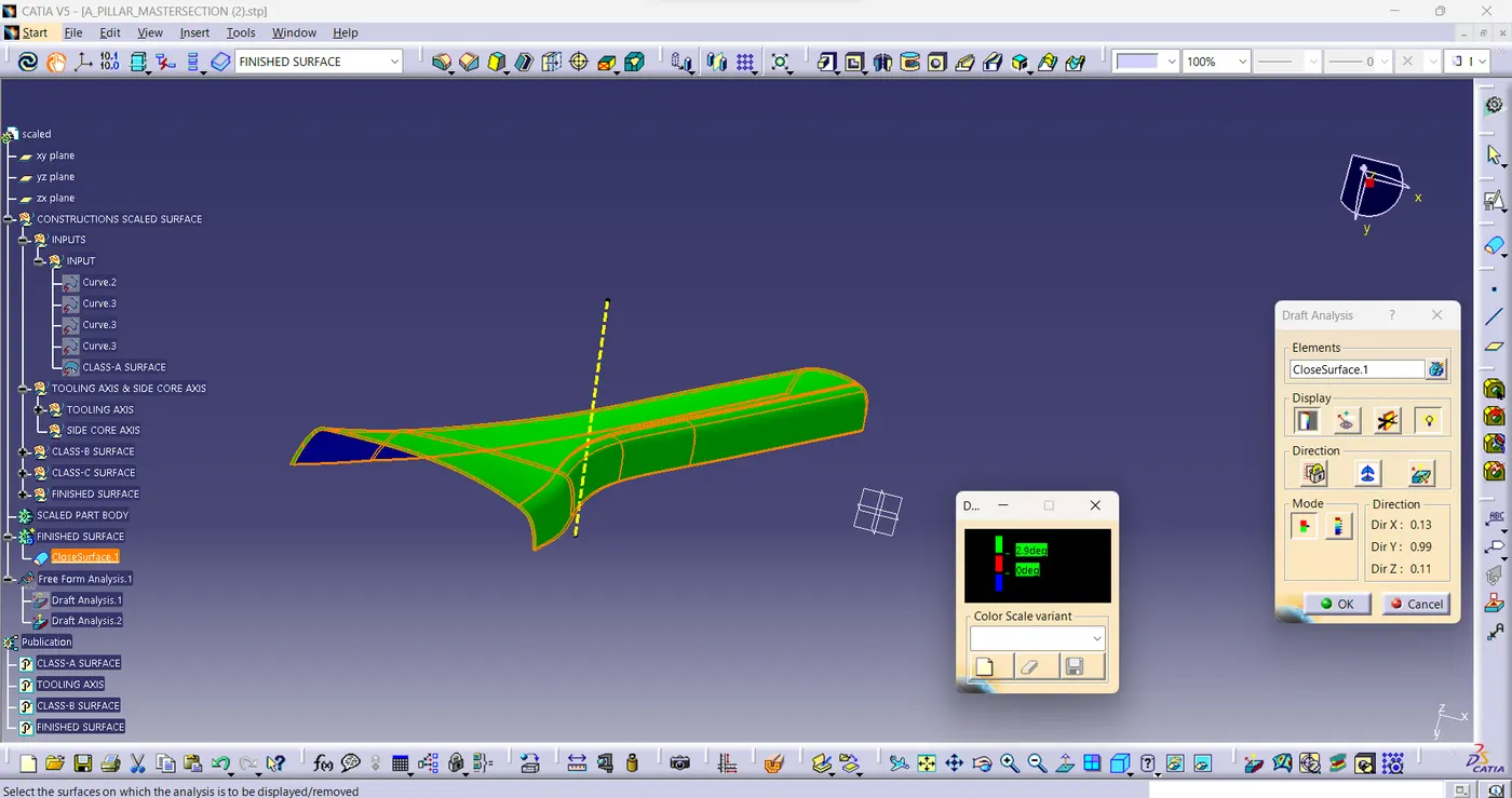
PART BODY OF CLOSED SURFACE,
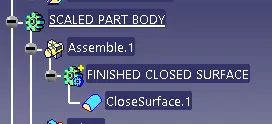
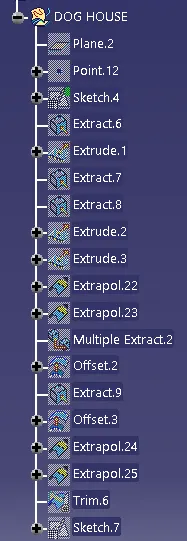
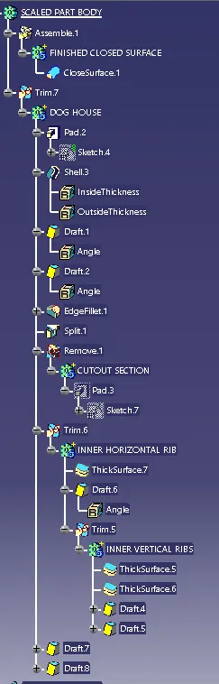
B- SIDE FEATURE(DOG HOUSE): Now for the B- SIDE FEATURE(DOG HOUSE), using the given MULTI SECTION i extracted the outer line and formed a AXIS SYSTEM with the SIDE CORE AXIS and created a point in the MULTISECTION. Now i sketched them for iso constrained and exit the work bench and changed to PART WORKBENCH, then used the PAD command to pad the sketch. Then using SHELL command i shelled the front and lower side of the pad for 2.5mm. Now for the top cutout section i used the AXIS SYSTEM's plane i sketched them with the given value and padded them in a spearate BODY called CUTOUT SECTION. Now i defined the work in DOGHOUSE BODY and conducted the BOOLEAN OPERATION in the CUTOUT SECTION to remove from the DOG HOUSE body and i DRAFTED them with 1.5mm for the DRAFT ANALYSIS. Now for the inside ribs i performed same extaction method from the MULTISECTION and EXTRUDED them and using THICKEN METHOD i thicken the surface in a SEPERATE BODYS to conduct the BOOLEAN OPERATION. I named the bodys has INNER HORIZONTAL RIB & INNER VERTICAL RIB now i conducted the BOOLEAN OPERATION of UNTRIM OPERATION on them and the same UNTRIM OPERATION has been done with the DOG HOUSE. Now i used UNTRIM OPERATION for whole body to untrimed with MAIN PART BODY.
Now i conducted the FINAL DRAFT ANALYSIS on both the ouside and inside of the DOGHOUSE with the both TOOLING AXIS & SIDE CORE AXIS and got cleared,
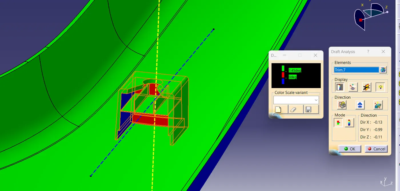
INSIDE
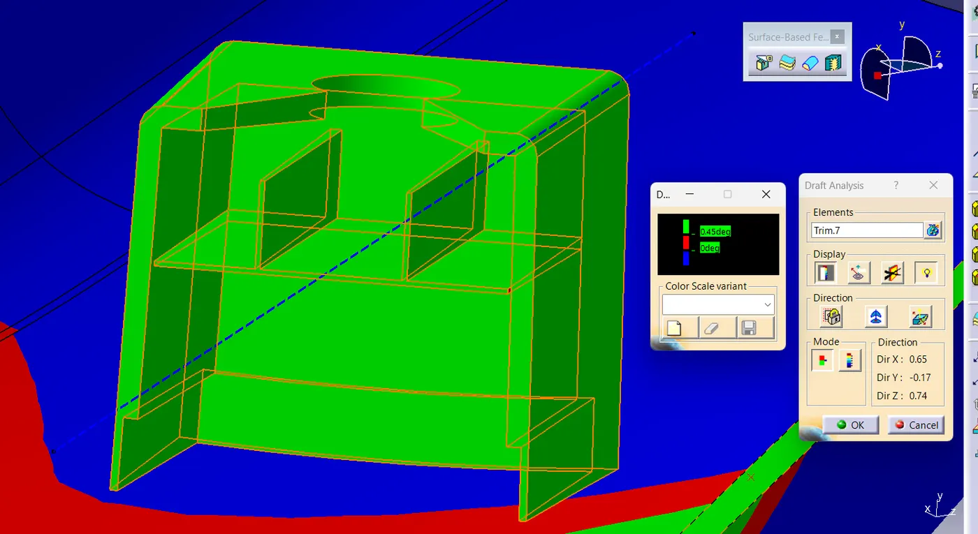
GEOMENTRICAL SET & PART BODY for the DOGHOUSE,
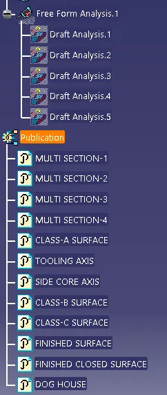
FINAL PRODUCT, DRAFT ANALYSIS, PUBLICATIONS,