Week 9 - Challenge 2 - Switch Bezel Design
SWITCH BEZEL: Downloaded the given CLASS-A SURFACE in the catpart.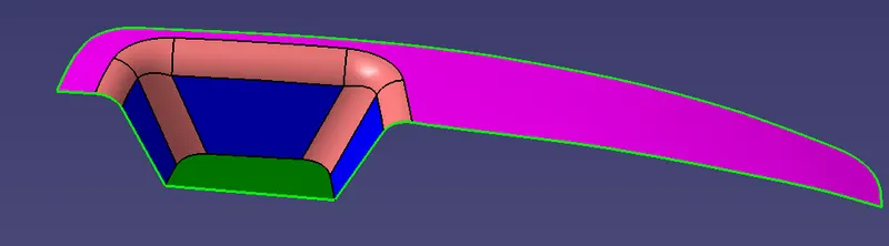
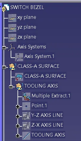
Then started working on the DRAFT ANALYSIS of the CLASS-A SURFACE, for the TOOLING AXIS, i started working in the BASE SURFACE of the given CLASS-A SURFACE by EXTRACTING and having a POINT. Then i placed the AXIS SYSTEM in the POINT of BASE SURFACE and started doing POSITIONED SKETCH to sketch a LINE in Y-Z AXIS of the AXIS SYSTEM by keeping the CLASS-A SURFACE and using the PROJECT 3D ELEMENTS command, i highlited the boundary of the CLASS-A SURFACE. I created two parralel to each other intersecting the projected 3D element line and using BISECTING command in line option and bisected and foarmed the FIRST DUMMY LINE. Then for the Z-X AXIS i used the POSITIONED SKETCH in AXIS SYSTEM to have a sketch of other line in x-axis. Now using INTERSECT 3D ELEMENTS commands i intersected the CLASS-A SURFACE and highlited the boundary of the 3D element, then created a line along the highlited area and another line in point in the direction of z-axis. Now i used CONSTRAINT command, i constraint the both the line of 4 DEGREE. After creating the LINES using LINE DEFINITION COMMAND in the line type option selecting the BISECTING command and selecting the created lines and bisect to have the TOOLING AXIS.
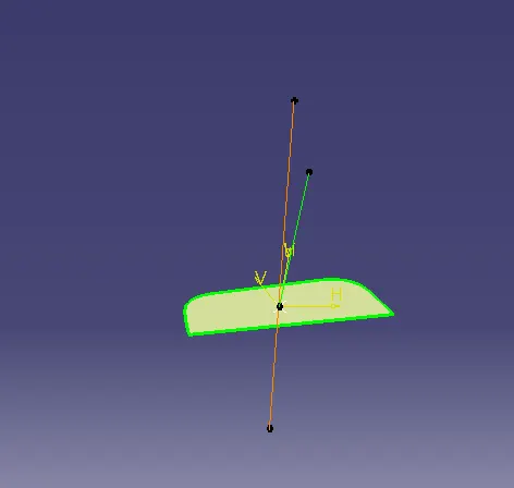
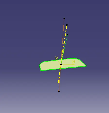
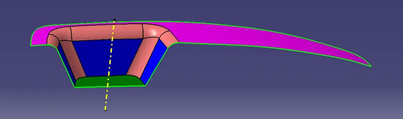
The TOOLING AXIS & CLASS-A SURFACE Geomentrical set given below,
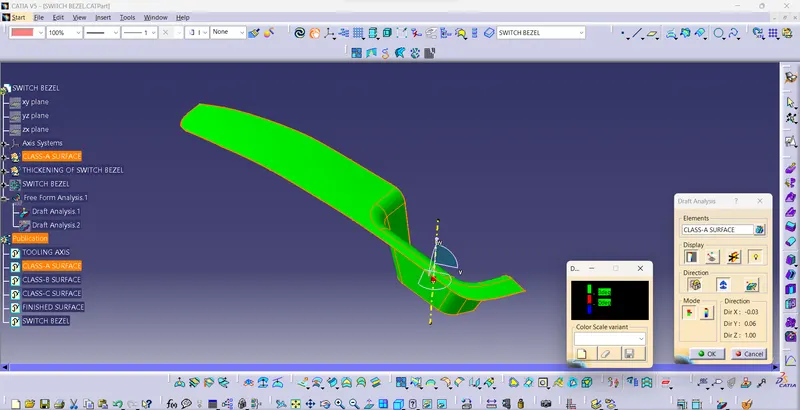
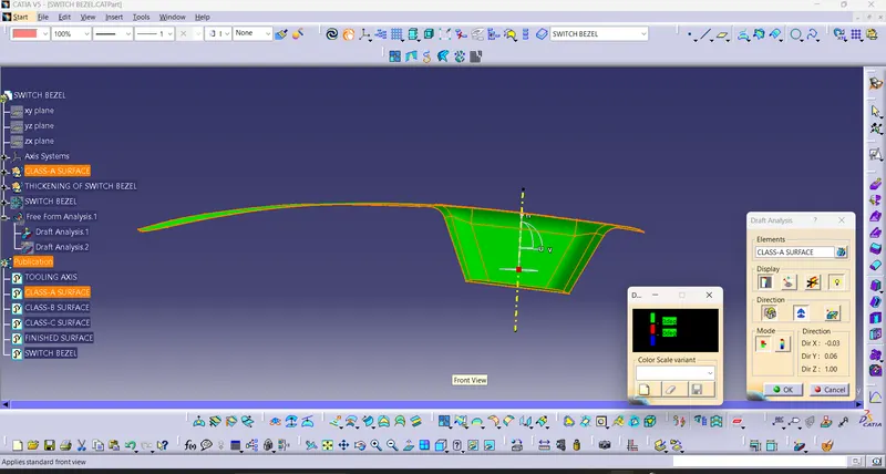
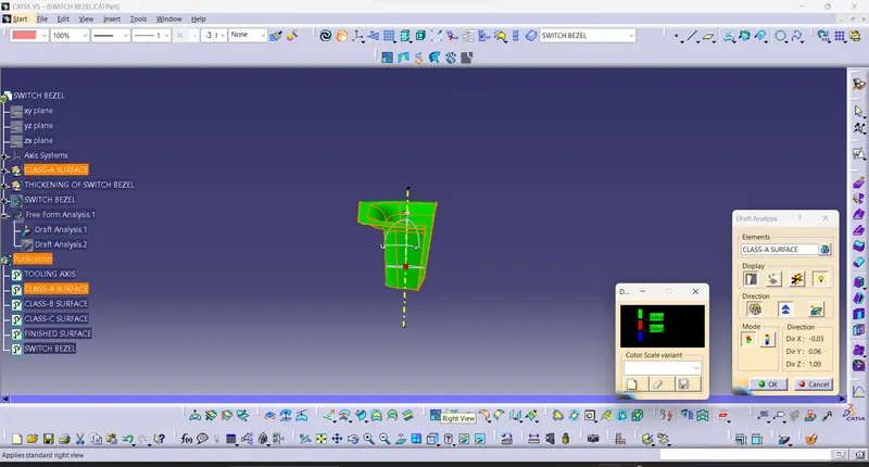
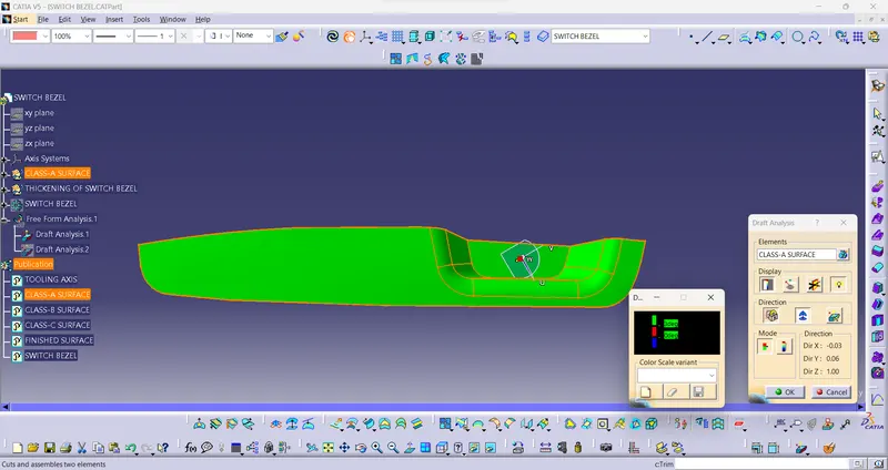
Now i PUBLISHED (CLASS-A SURFACE & TOOLING AXIS) and then i go for the DRAFT ANALYSIS of the CLASS-A SURFACE. Using DRAFT ANALYSIS, i selected the CLASS-A SURFACE for elements, i given a minimal value of 3 DEGREE in the QUICK ANALYSIS DIALOG BOX and then dragged the COMPASS and placed in the created TOOLING AXIS. The outcome was given in the GREEN colur.
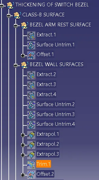
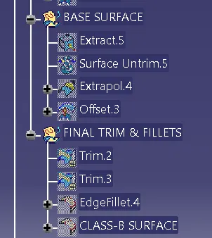
CLASS-B SURFACE: Then creating a GEOMENTRICAL SET(THICKENING OF SWITCH BEZEL) as a parent i created another GEOMENTRICAL SET(CLASS-B SURFACE) using EXTRACT TOOLBAR i extracted the surfaces other than the fillted part in the CLASS-A SURFACE, then using UNTRIM TOOLBAR to untrim the exracted surfaces and EXTRAPOLATED the surfaces for 10mm and trimed the surfaces for suitable surface by using TRIMMING TOOL. Then offseted the trimed surfaces for given thickness 2.5mm and given a colour for identifying CLASS-B SURFACE from the CLASS-A SURFACE. Unhiding the CLASS-A SURFACE to analyze the created CLASS-B SURFACE, then using VERNIER CALLIPER TOOL to get dimension of the fillet from the CLASS-A SURFACE and creating the fillet top of the CLASS-B SURFACE by adding thickness value to the fillet value.
GEOMENTRICAL SET for BEZEL ARM REST SURFACE, BEZEL WALL SURFACES, BASE SURFACE, FINAL TRIM & FILLETS of CLASS-B SURFACE given below,
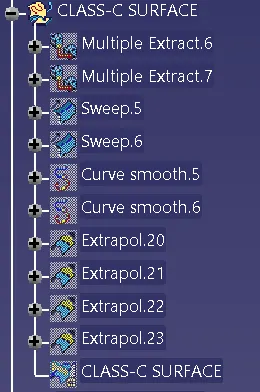
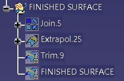
CLASS-C SURFACE & FINSHED SURFACE: I created another GEOMENTRICAL SET(CLASS-C SURFACE) In this, i hided the CLASS-B SURFACE and unhiding the CLASS-A SURFACE and started working on it, using MULTIPLE EXTRACT COMMAND TOOL i extracted a boundary for the CLASS-A SURFACE and then selected the SWEEP COMMAND to given a sweep of 20mm outward of the part of the CLASS-A SURFACE by the help of TOOLING AXIS. Using the SMOOTH CURVE command i smoothed the surface of the CLASS-C SURFACE. Unhiding CLASS-B SURFACE analysing whether the CLASS-A SURFACE intersecting eachother and using another GEOMENTRICAL SET(FINISHED SURFACES) i trimmed the CLASS-A SURFACE & CLASS-B SURFACE, but there was a slight opening in the boundary due to SMOOTH CURVE command. So by using EXTRAPOLATED COMMAND i extened the CLASS-A SURFACE to 0.05 in length. Then using JOINT command, i joined the both the CLASS-A SURFACE & CLASS-C SURFACE and using TRIM, command, i trimmed the joined surface with the CLASS-B SURFACE. Thus foarming FINSIHED SURFACE without a boundary.
GEOMENTRICAL SET CLASS-C SURFACE, FINSHED SURFACE given below,
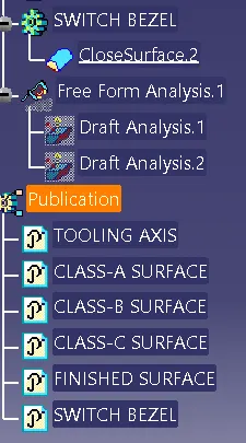
Changing to the PART WORKBENCH selecting the final surface and created a solid finished product using CLOSE SURFACE command in the PART BODY.
GEOMENTRICAL SET for PARTBODY, DRAFT ANALYSIS, PUBLICATION given below,
FINAL PRODUCT given below,
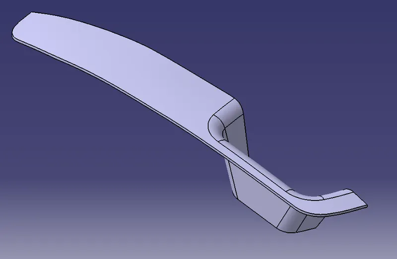
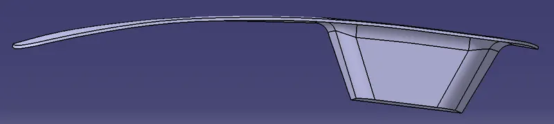
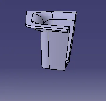
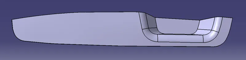
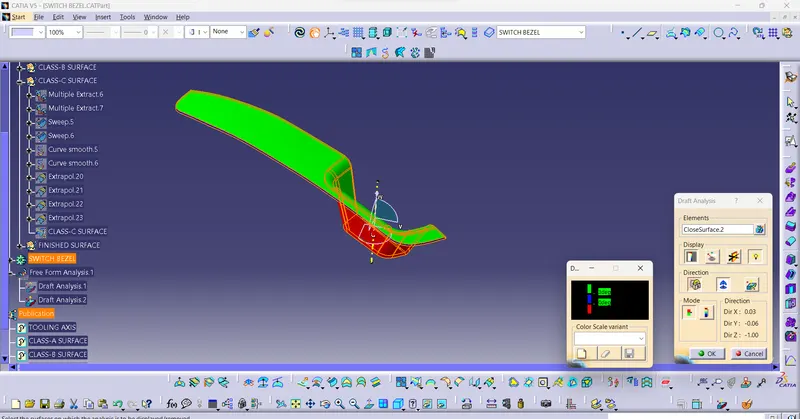
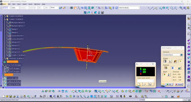
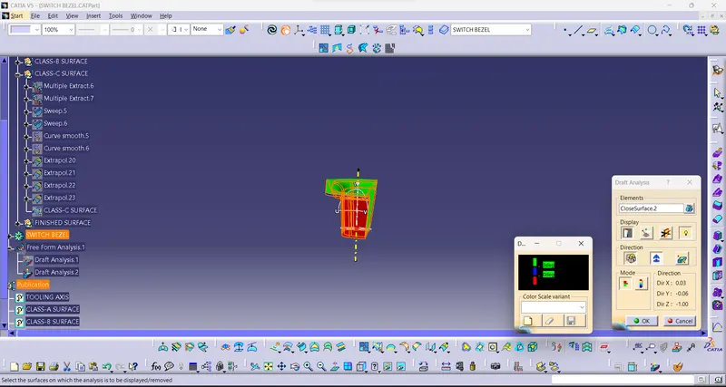
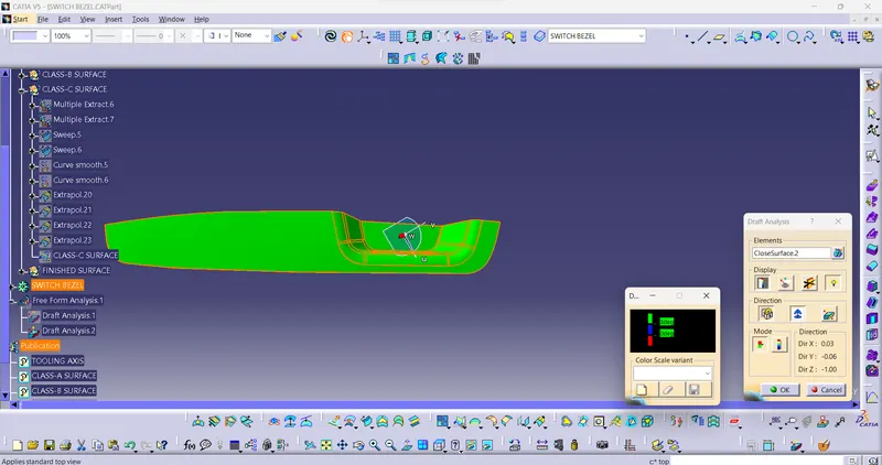
DRAFTING ANALYSIS OF FINAL PRODUCT: Thus finishing the final product, now unhiding the TOOLING AXIS for the final product to start the DRAFTING ANALYSIS. Now opening the DRAFT ANALYSIS tool setting minimal value of 3mm in quick analysis dialog box, and dragging the COMPASS to the TOOLING AXIS and got the output given below,