Week 11 - Project - A pillar Design with Master Section
A PILLER DESIGN WITH MASTER SECTION
OBJECTIVE:
Create the A Piller component through the given class A surface. To begin with, the tooling axis for the given class A surface should be created meeting the requirements of the draft angle and at the end perform the Draft analysis on the model. Create the DOG HOUSE considering the design rules mentioned.
INTRODUCTION:
First, we have to create the required Tooling axis for the given class A surface. Then perform Draft analysis on the class A surface.
After that we have to create the class B & C surfaces. Create the DOG HOUSE at the B Surface. Then join the final plastic component and perfom Draft Analysis.
SPECIFICATION:
Thickness of the component = 2.5mm
CLASS A SURFACE:
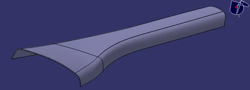
Class A surface is an aesthetic surface with highest quality finish. Most class A surfaces for an automotive component are made using Autodesk-Alias based on the final concept-sketch.
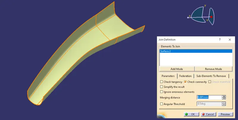
All class A surfaces should have Curvature-continuity which means the continuity between the surfaces should share the same boundary. It is taken as a reference by the Automotive Pastic Designer to create the Class B and Class C surfaces.
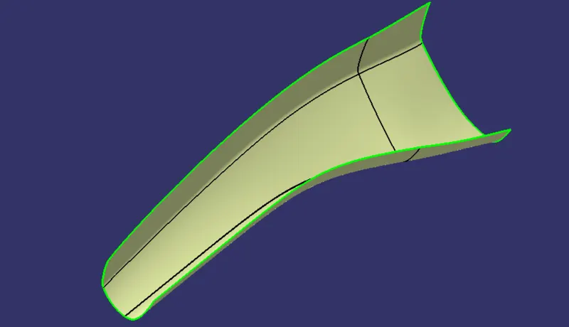
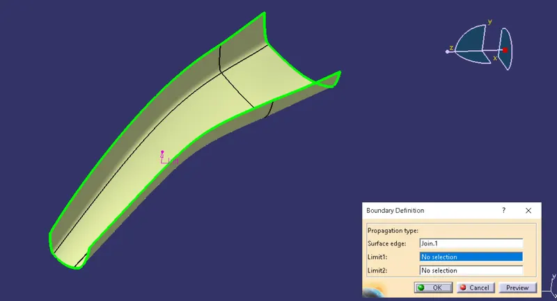
Import the given Class A surface, Check for continuity using boundary and create the tooling axis for the Class A surfaces and perform Draft Analysis.
TOOLING AXIS:
It is the direction in which the core and cavity opens and closes. After the class A is imported check for possible irregularity, using boundary.
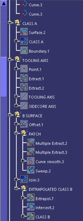
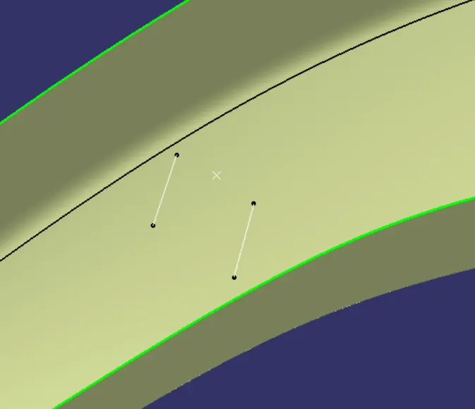
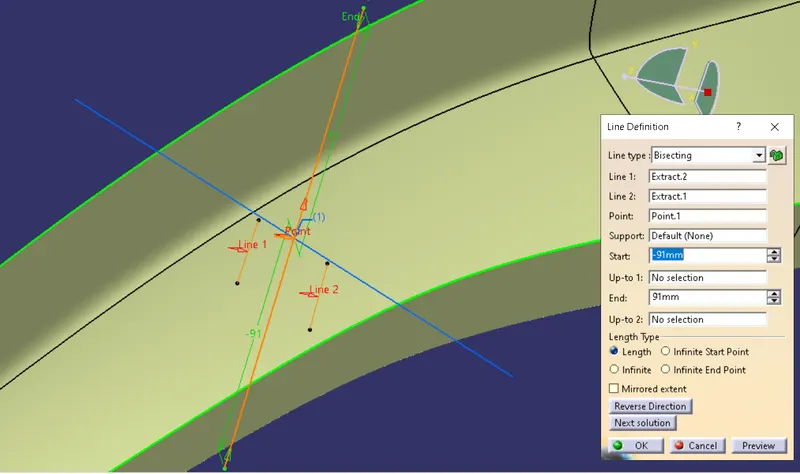
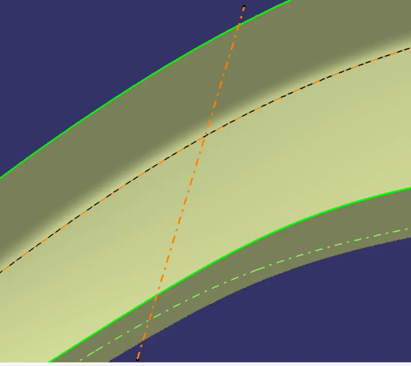
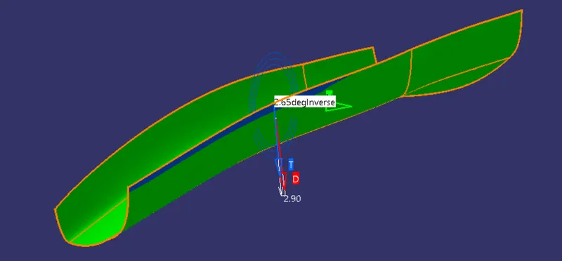
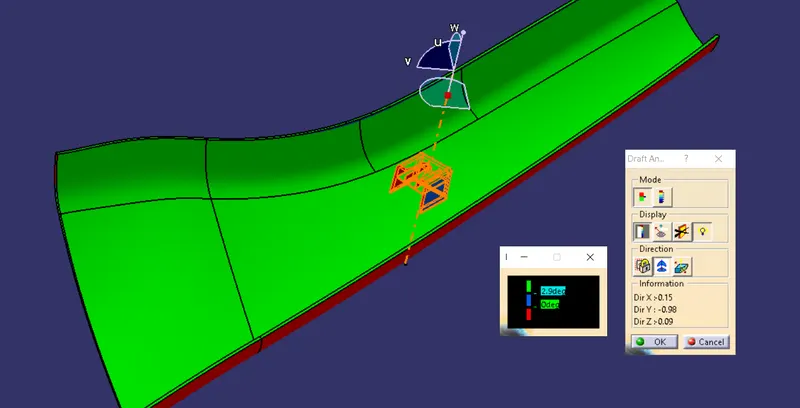
Extract two lines from the master section, Use the lines to Create the TOOLING AXIS by BISECTING METHOD. The created line is the tooling axis, perform draft analysis on the class A surface using tooling axis.
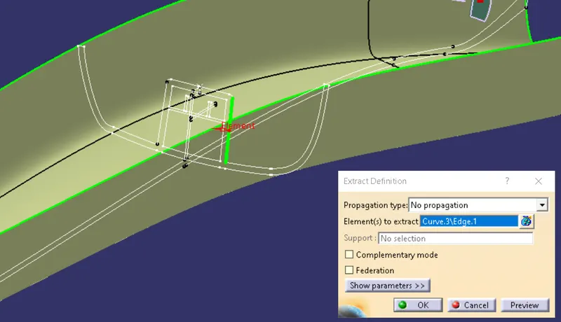
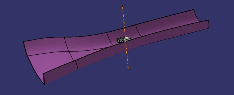
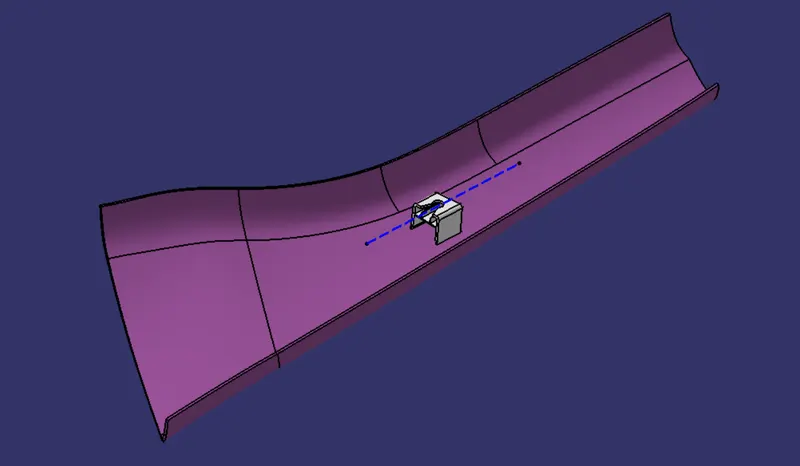
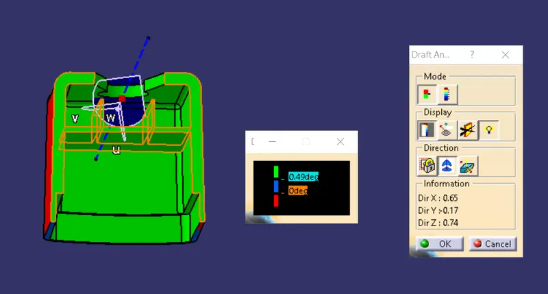
The Side core axis is created for Draft Analysis on the DOG HOUSE, Draft analysis for the DOG HOUSE should be performed seperately.
DRAFT ANALYSIS:
No parts can be ejected from the tool if it is having a straight 90degree profile from its base surface. A small draft angle is provide to component in order to get an easy removal from the tool. Draft analysis technique is used to analyze whether our part model created is manufacturable based on the draft condition applied.
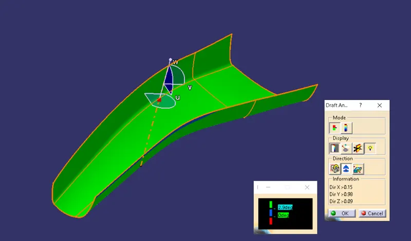
To start the draft analysis, we will go to insert and click on the option called analysis. Select the Feature Draft Analysis, click on Quick Analysis option on mode. Under direction we will choose the icon with the symbol of compass on it. Place it on the tooling axis.
CLASS B SURFACE:
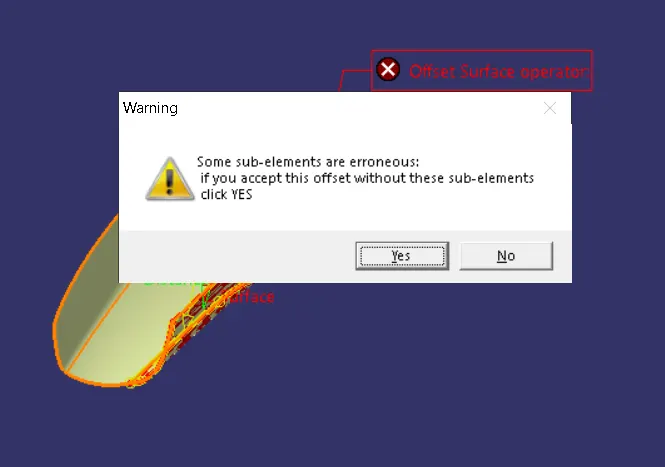
The B surface is created by OFFSETING the CLASS A SURFACE. B surface contains features like Locator, Heat stake and DOG HOUSE. A Error occur While Offseting the Class A surafce, A specific part of surface is missing. Close the surface to get the complete B surface.
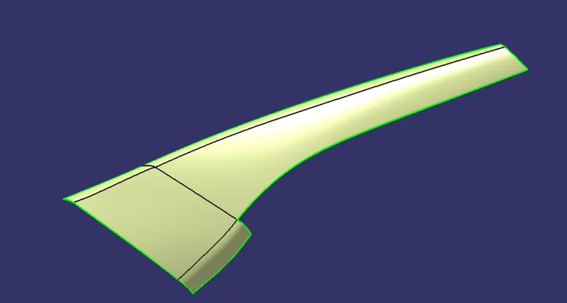
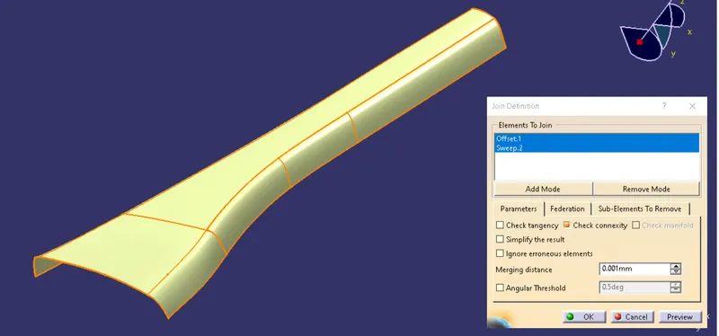
Extract the two edges, Do a Sweep based on the refernce surface option and join the offsetted class a with the sweep to get the complete Class B Surface.
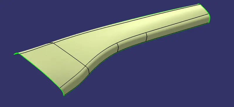
CLASS C SURFACE:
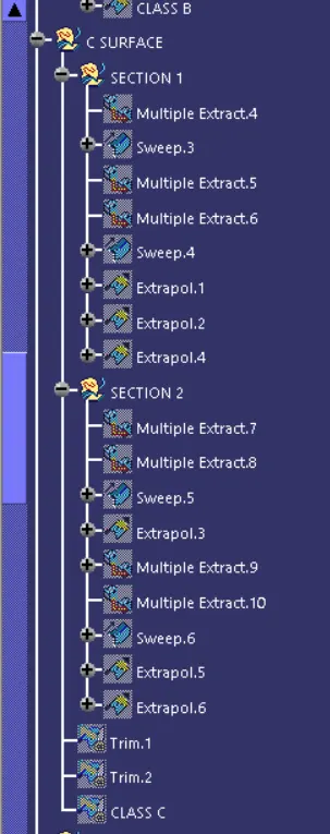
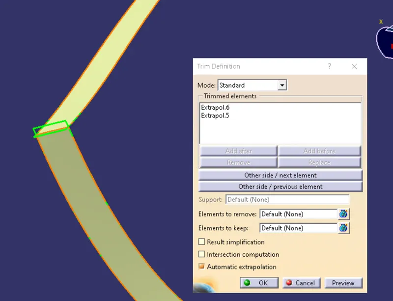
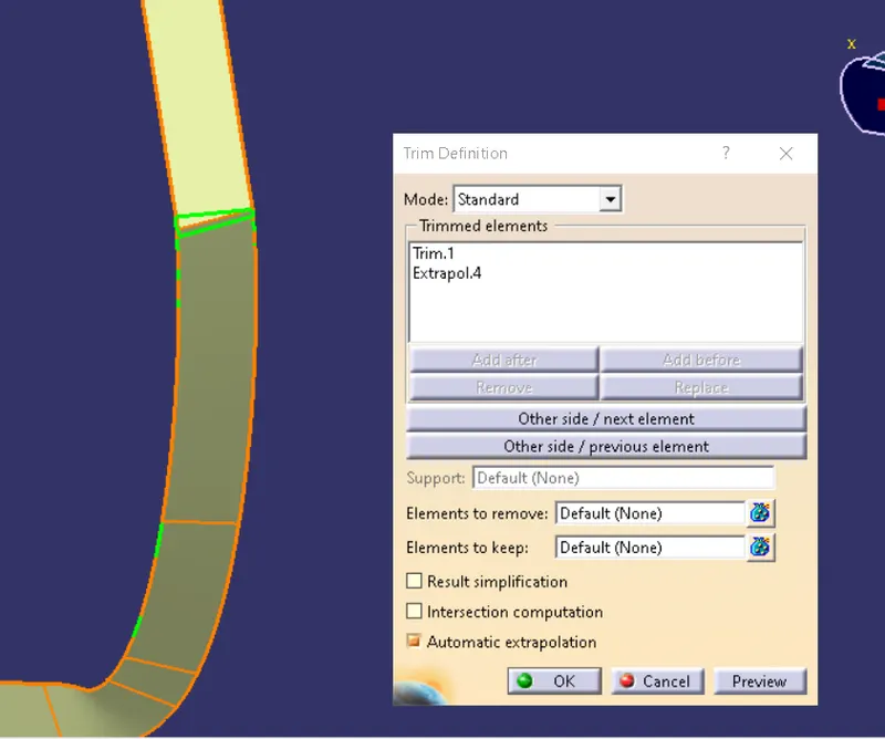
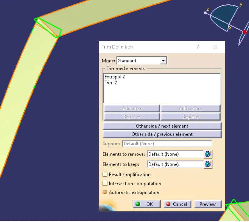
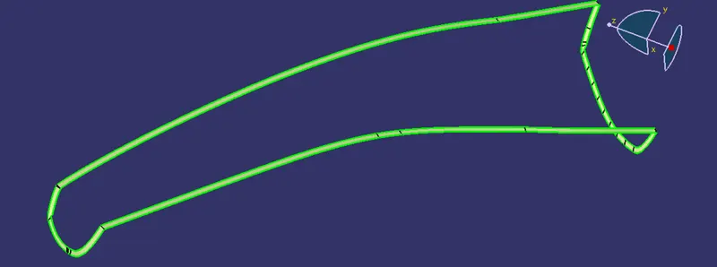
Do Sweep on the edges of the CLASS A using Reference surface and Draft Direction. I converted it into Sections and trim them together to get Class C surafce.
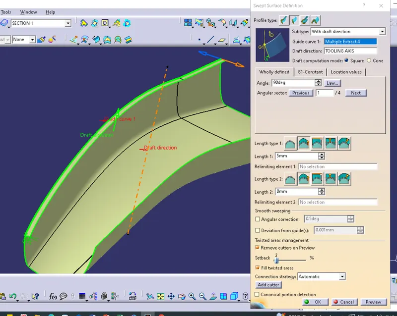
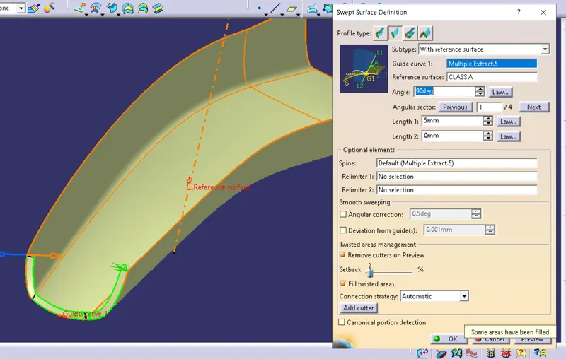
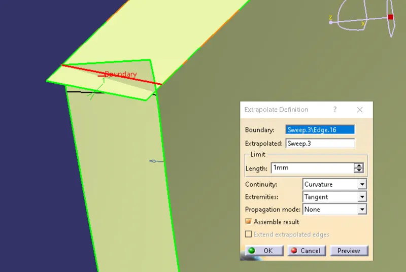
Extrapolate the Sweeps to intersect with other Sweep to Trim them together.
CLASS A AND C SURFACE:
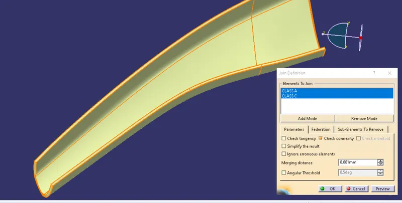
Join the Class A and C Surfaces together.
FINAL TRIM:
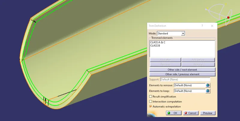
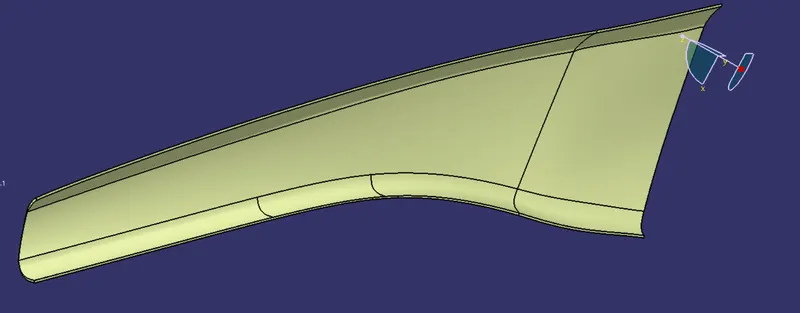
Trim the above surface with the extrapolated B surface To get the Plastic Component. Open the part workbench convert the plastic component into Close Surface.
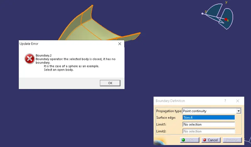
Final Boundary Check.
DOG HOUSE CREATION:
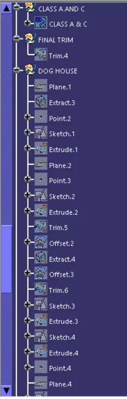
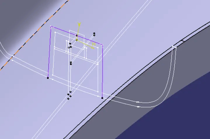
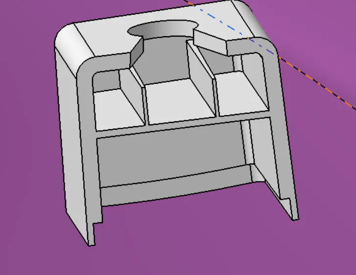
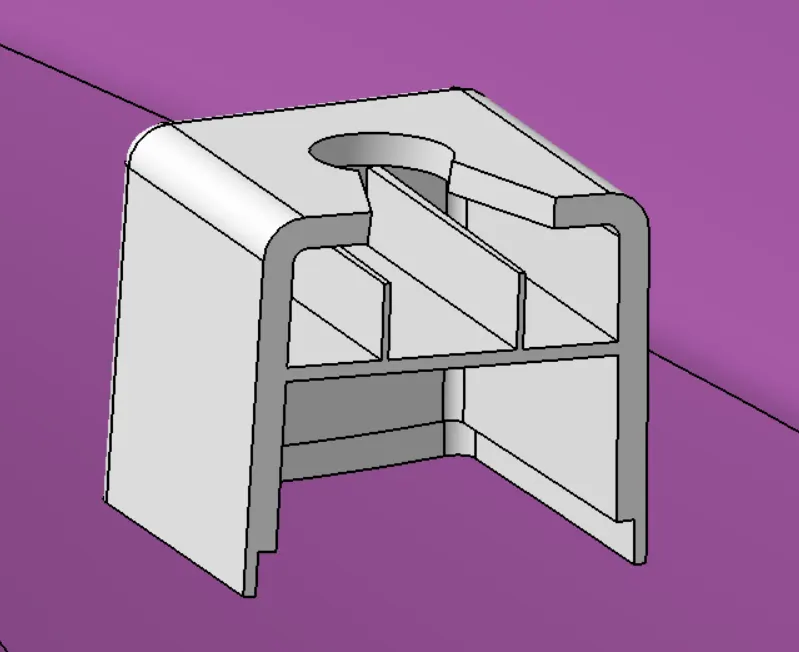
Refer the master section given to get the sketch for the dog house, Extrude the outer edges and close the surface to thicken the component.
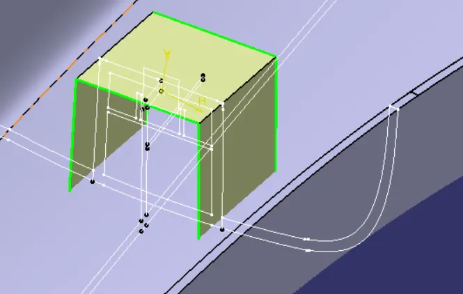
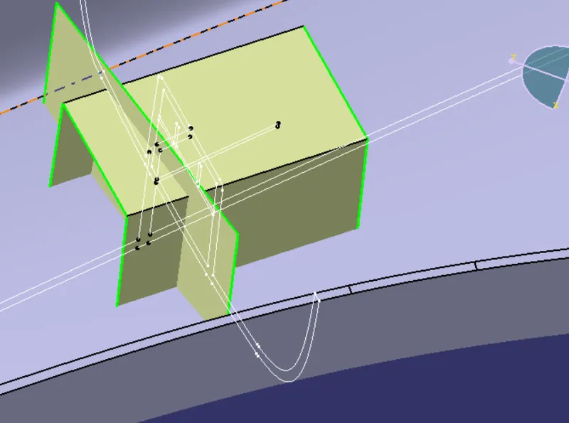
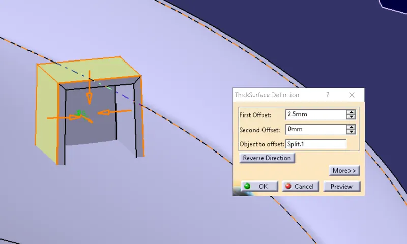
After thicken the component, Draft the dog house 0.5mm.
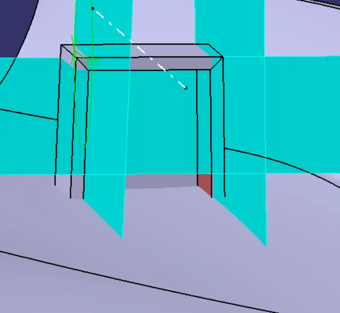
cut the lower region of the doghouse.
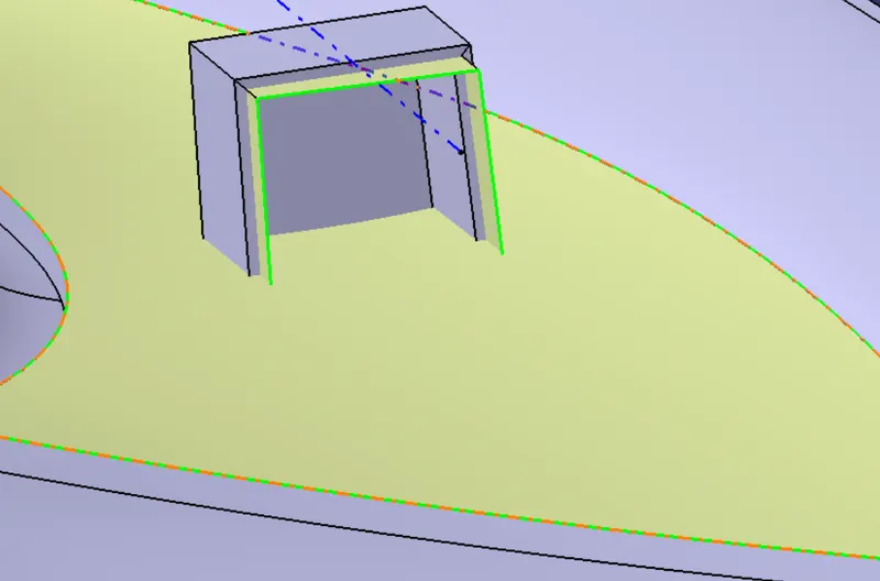
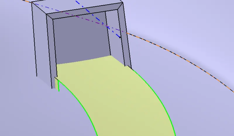
Draft the lower region of the dog house.
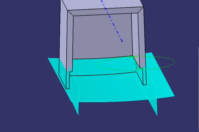
Remove the drawn region from the top of the dog house.
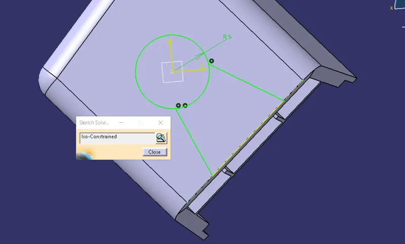
Extrude the inner region and thicken them and add the thicken surface into the Dog House.
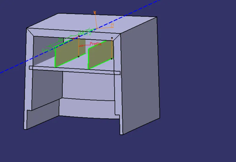
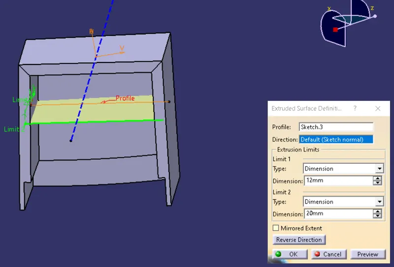
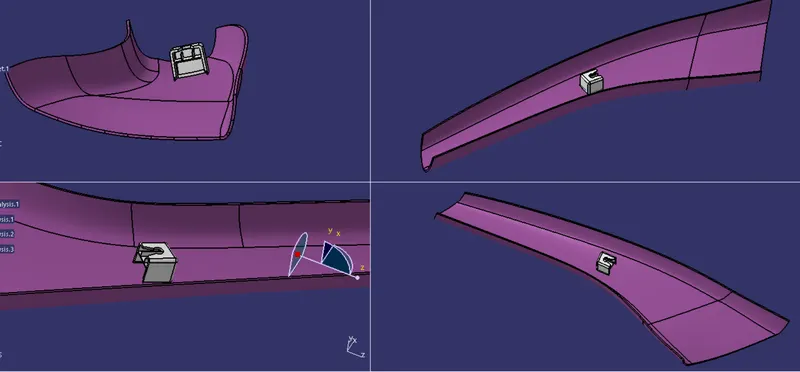
FINAL DOG HOUSE:
DOG HOUSE DRAFT:
FINAL DRAFT:
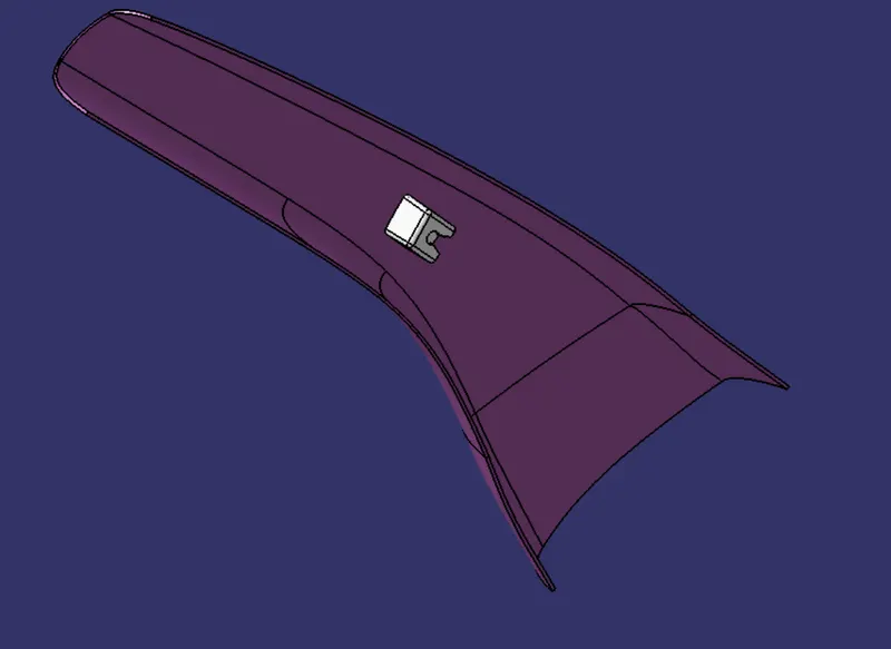
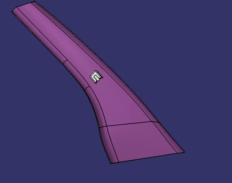
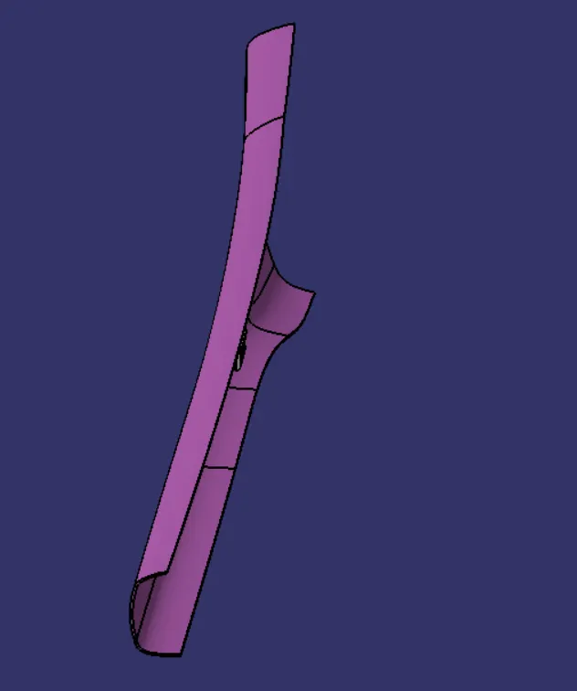
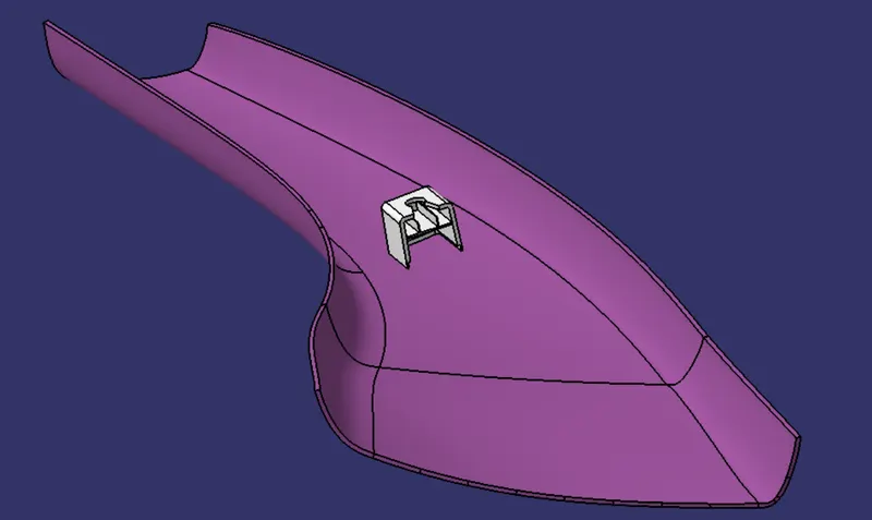
VIEWS:

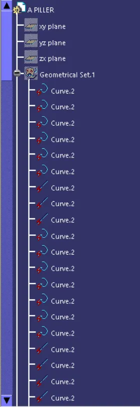
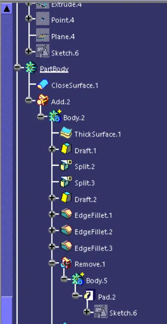
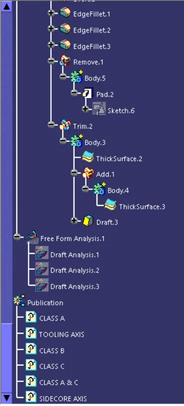
TREE STRUCTURE: