Week 11 - Project - A pillar Design with Master Section
Project - A pillar Design with Master Section
Aim:
To create the A-Pillar's Plastic component from the given Class A Surface and create the Engineering Bside Features by using the given Master Sections.
Objective:
- To create the tooling Axis and Performing draft analysis on the Class A.
- To Design the A Pillar by following the design rules (Create Class B & C surface).
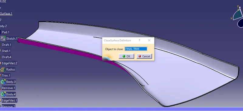
- Use the Close Surface feature to make a solid body from the surface.
- To create the Bside Engineering Features by considering the design rules.
- Perform the Draft analysis for the final component.
Pillars:
Pillars are standing at the vertical or near-vertical (slightly inclined) position are structural supports for the car's roof and window areas and attached to the wheel arch.
They are pretty important as they provide a strong foundation to install the glass (windscreens, rear, and side windows) of your car. Also, these are strong enough to hold the entire roof (even with roof racking to carry additional weights).
There are several pillars your car can have, and each has got a name. Pillars are named “A”, “B”, “C”, or “D” (in larger vehicles), if you move from the front to the rear end of your vehicle.
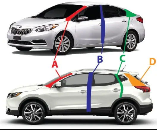
A-Pillar is located on either side of your car’s front window (or windshield).
They also hold the hinges of your front doors. A-pillars are normally made of steel alloys.
Besides being a supporting member, A-pillars are very crucial as far as safety is concerned. A-pillars usually carry a significant amount of load during a frontal collision or a rollover crash. So the larger the width or cross-section, the greater would be the strength but A-pillars always block the driver’s vision (create blind spots) to some extent that can be realized while driving. So, having that said, using thicker A-pillars can make the situation even worst. It might further lower the driver’s vision and raise a question about the vehicle’s and passenger’s safety.
Hence, the design of A-pillars must be optimized giving equal importance to both strength and the driver’s vision.
Tooling Axis:
- To analys the class A surface first create the Tooling Axis, the tooling axis is tends to the core and cavity direction. So the tooling direction is defined to the component ejecting direction.First create the plane perpendicular to the core and cavity area.
- Here Tooling axis is little differen from other model, by useing the Bseide Dog-House Master section is the reference to create the tooling axis.Project the Dog-House wall Line and isolate them for break the parent-Children relatioship between Master section and tooling axis.Then Crate ythe line by the options of Point-Point Line type.Then Create the Bi-Secting Line between these two lines.
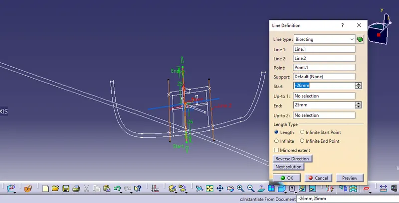
Then create the isolated line from the master section form front and back of the dog-hous reference and create the Bi-secting Line.
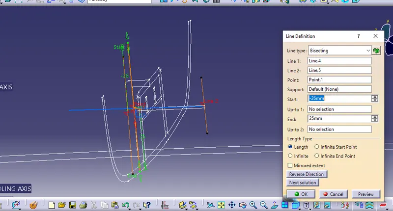
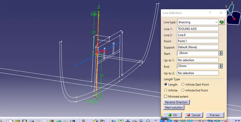
Using these two Bi-secting line create the new Bi-secting Line and the origin from the Dog-House master section reference is the Main Tooling Axis.
Class A:
Class A surface is the aesthetic skin data for the automotive part designing and curvature surface to represent the main component.Befor proceed with A surface to analys the Draft angle, if get any mis-match surface reconstruct the A surface.
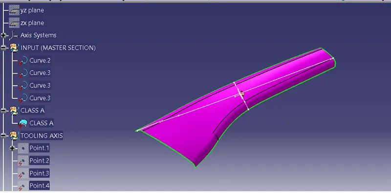
Class A Draft Analysis:
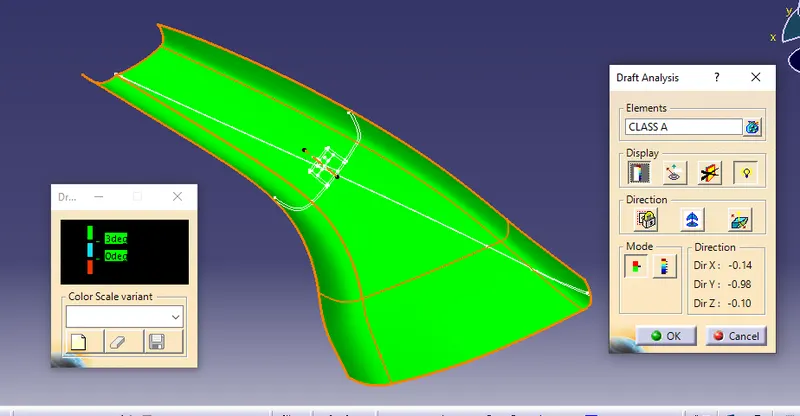
Draft is the main requirments in plastics molding. If the draft angle is less than 0 degree, the part or component and tool is to be damaged in mass production. If the draft angle is less than 0 degree, the part or component and tool is to be damaged in mass production. Also the molding part would not eject from the core and cavity. So avoid the damage and lack of productin the drafting analysis to find out the lesser angle are by the colour variation.
Class B:
For create the class B surface here we directly offset the class A surface to the total thickness of close body to inward direction some of the surfaces give offset error and ask for offset without these subelements click okay and work on the incomplete surfaces by using the multi-section surface command or extrapolate, fillet and different commands used to complete the class B surface.
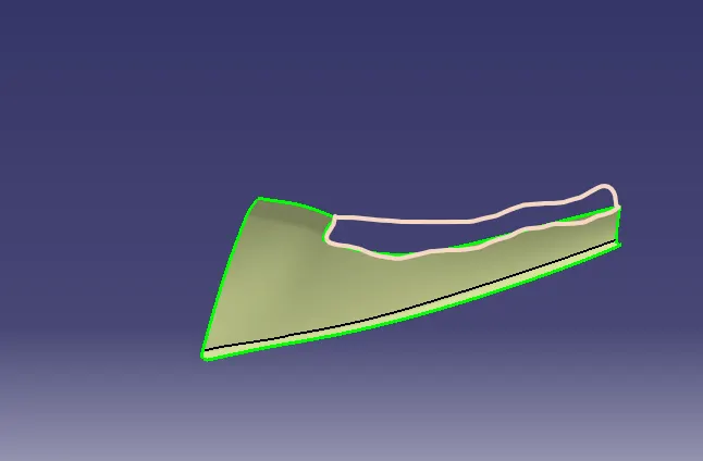
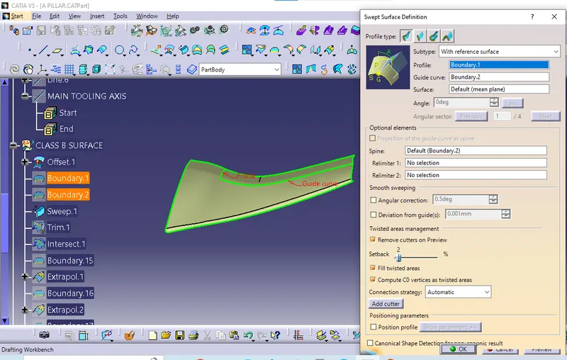
Here is not offsetting properly due to the complexity of the curvature of the Class A Surface and hence we have to recreate that missing patch using tools such as Sweep Command as shown below image.
Class C:
We first createste boundary from the Class A surface edges with the help of the multi extract or boundary command which we create the curve for sweep command. For creating the C surface draw a boundary to the class surface edges and sweep the edges with draft direction and with reference surface. The surface which is paralel to the tooling axis to use the sweep at the draft direction and the surface which is perpendicular to the tooling axis is swept with the reference surface.
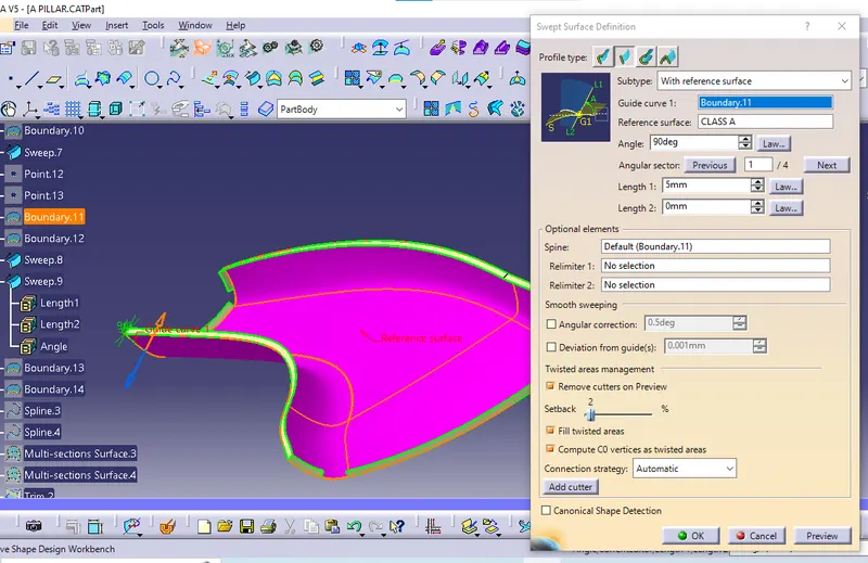
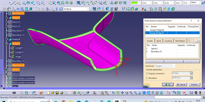
Some of the curved area difficult to create the sweep,so use multi section surface by the support of spline and boundary.
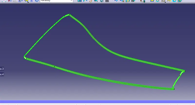
Class A & C:
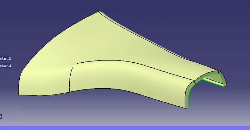
To join the class A and Class C surface by using join command.
Final Trim:
To trim the Surface (A+C ) with the B surface.
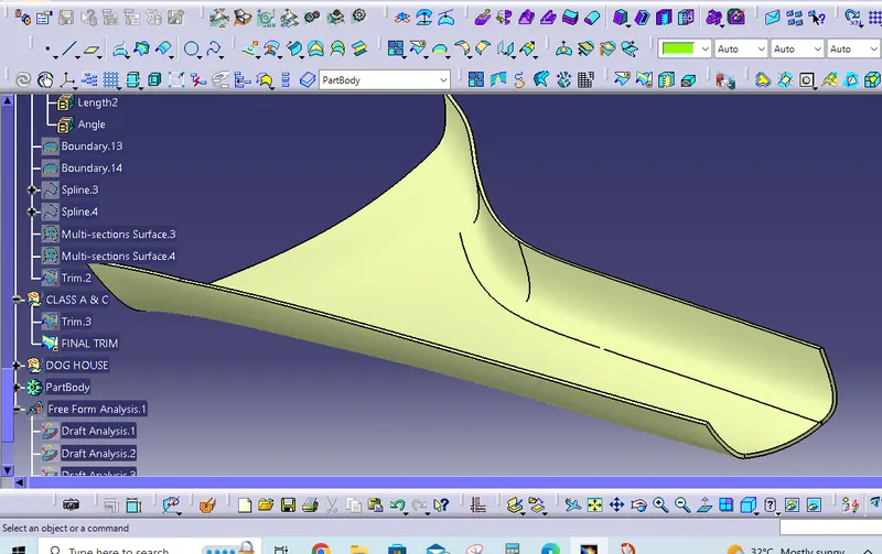
Close Solid Surface:
START -> MECHANICAL DESIGN -> PART DESIGN -> SURFACE FEATURE -> CLOSE SURFACE
Master Section:
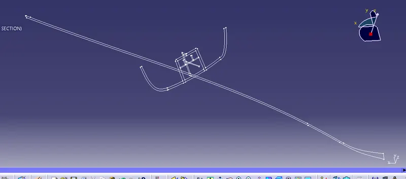
Using this master section create the Bside Engineering Features by considering the design rules.
DOG HOUSE DESIGN:
Dog house is an engineering feature used in the plastic trim design. Dog houses are used as supporting features. Sometimes other engineering features like boss; locators, etc. are mounded on them to increase their dimension and strength. Dog house and other engineering Features are built on final close solid body.
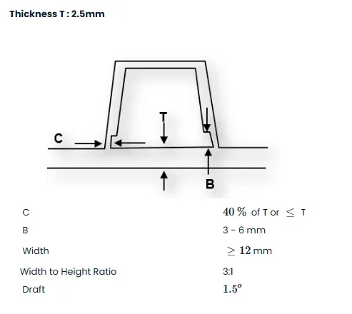
Design rules for Dog house creation
Dog house is an engineering feature used in plastic design. Dog houses are used as support feature. Sometimes other engineering features like snaps, locators, screw bosses are mounted on them to increase their strength.
Dog houses are subjected to draft analysis to prevent breakage of the component during ejection from the mould cavity. Dog house and other engineering components are built on the B-surface
Side Core Axis:
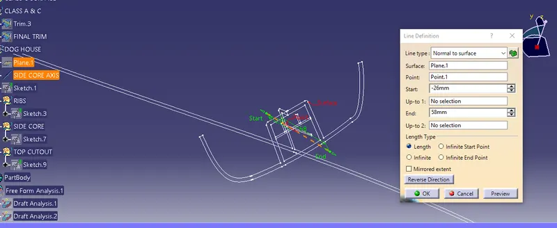
To create the side core axis orgin from the master section and create the line by Normal-Surface option and the surface is new plane on the master section and create the line as a Side core Axis.
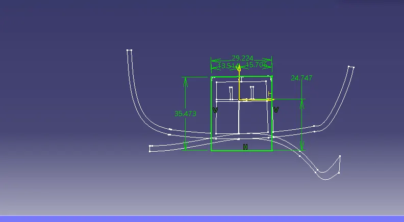
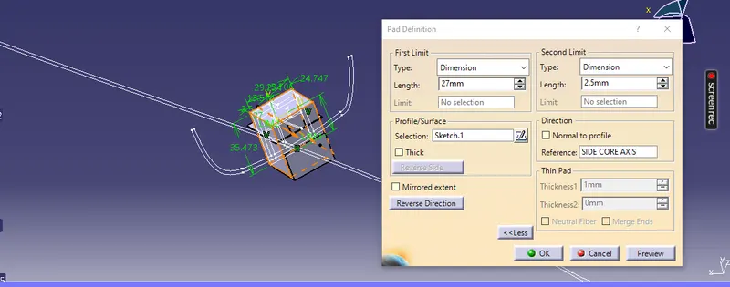
Create the sketch and project the master section and isolate for break the parent-children relationship between the master section and dog-house.Then constrain all the dimensions and create the body and pad it.
Draft:
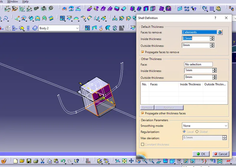
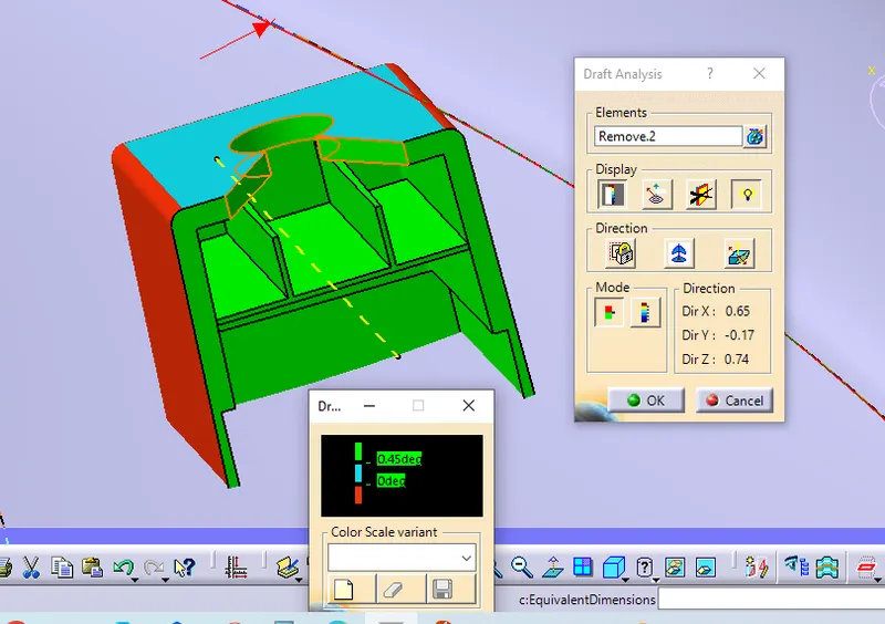
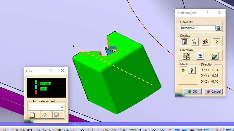
Draft the dog house body at the angle of 1.5° and the neutral element is bottom of the pad or plane, tooling axis is main tooling axis.
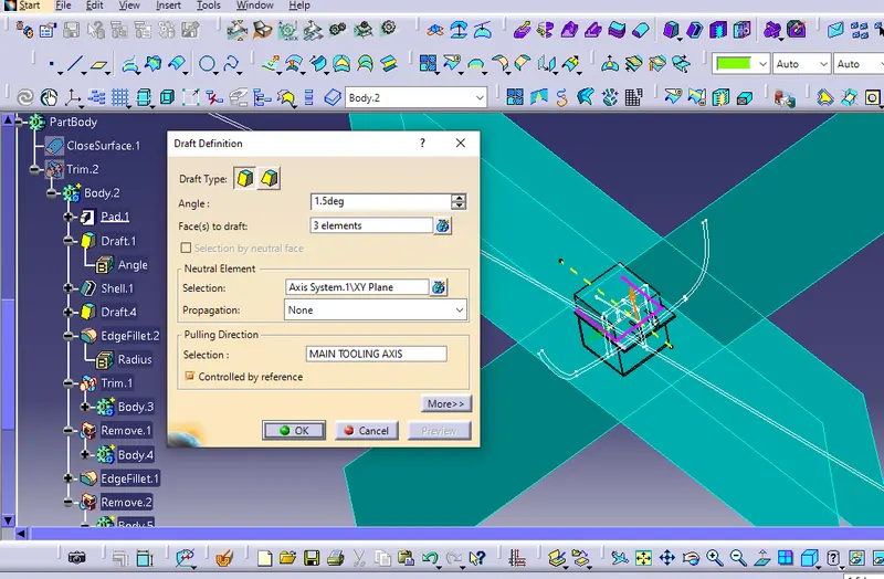
Make it shell and the thickness is same as the wall thickness of the closed body.
Ribs:
Create the sketch and project the master section and isolate for break the parent-children relationship between the master section and dog-house.Then constrain all the dimensions and create the body and pad it. 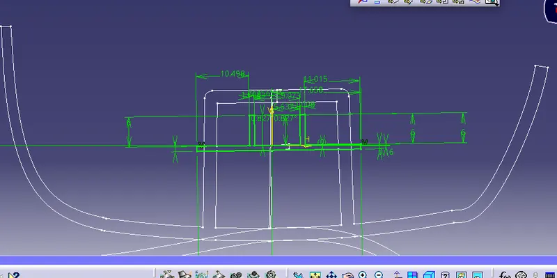
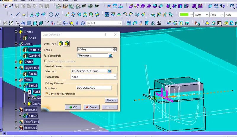
Draft theRibs body at the angle of 0.5° and the neutral element is Back side., tooling axis is Side core axis.
Top Cut-out
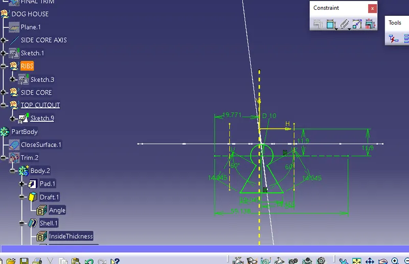
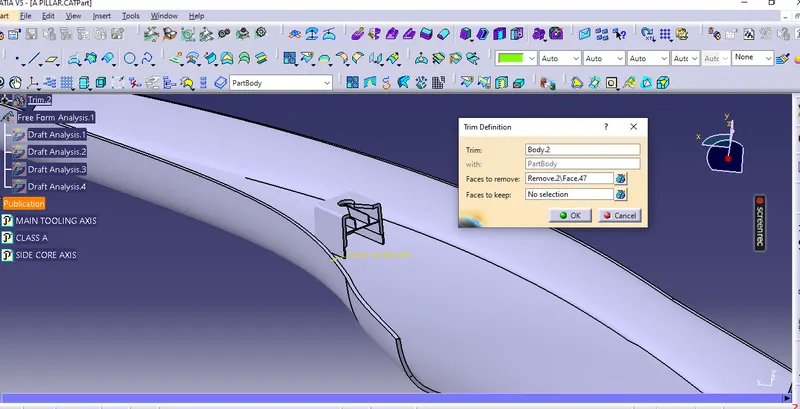
Finally Union trim the Dog-House to the Closed Apiller Body and remove the unwanted faces,
Final Close Body Draft Analysis:
Procedure for performing the draft analysis are as follows
- Change the view mode of the component into customized parameter mode and then select the shading option as material mode.
- Then open the featured draft analysis tool from the insert menu -> Analysis.
- Then click the compass and drag the axis to define the current drafting direction to tooling axis.
- Then lock the draft direction and perform draft analysis by pick the component.
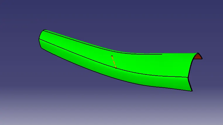
- The green colour shows the positive daft tooling direction and the given surface passes the draft analysis.
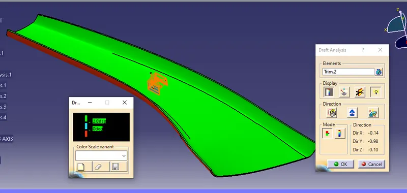
The final draft analysis the close surface clear by the draft angle.In Plastics design 3 degree is the minimum draft angle to drafted over the area which is permissible at the injection molding manufacturing area.Here the class A surface clear 3 degree draft, so the final close body also clear in 2.8 degree draft is accepetable in plastics design.
Dog-House Draft Analysis:
Different Views
FRONT VIEW
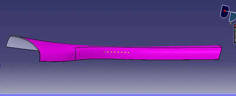
SIDE VIEW
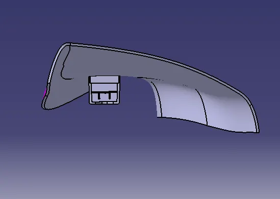
BOTTOM VIEW
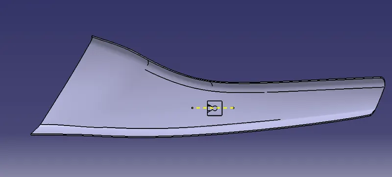
ISO VIEW
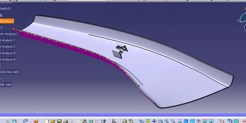
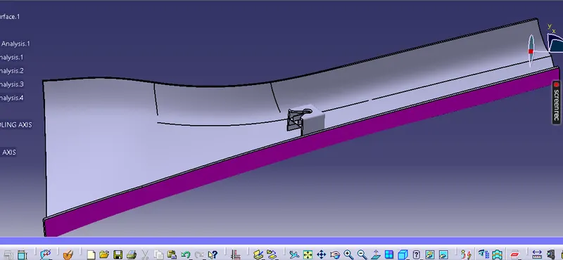
TREE STRUCTURES
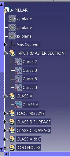
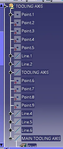
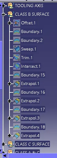
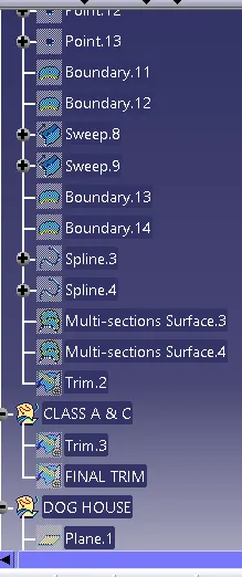
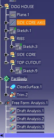
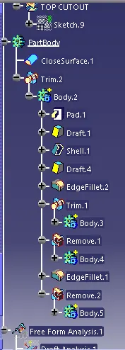
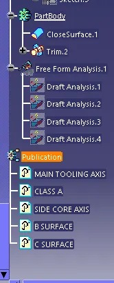
CONCLUSION:
Hence the tooling axis and Draft Analysis is done for a class-A surface and final close solid component of A-Pillar and adding the engineering features of dog house by the Master section was done successfuly.