Week 11 - Project - A pillar Design with Master Section
AIM: To create the A-Pillar's Plastic component from the given Class A Surface using the Master Section that is provided while following all the design rules.
THEORY:
- Pillars - Car pillars are components that support the structure of an enclosed automobile body. This is similar to that of a house with pillars supporting the roof over the floor. Car pillars are designed to stand in near vertical or inclined positions to support the roof.
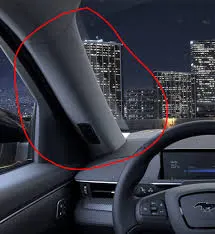
- Types of Pillars -
-
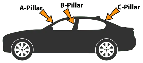
A-Pillar is the foremost pillar of the car, the one that holds the windscreen.
- B-Pillar is the pillar on both sides just behind the driver's seat.
- C-Pillar is the 3rd pillar generally behind the passenger's seat.
- Any pilllars behind that are named with the following letters.
- Role of the Pillars -
A-Pillar is located on either side of your car’s front window (or windshield).
They also hold the hinges of your front doors. A-pillars are normally made of steel alloys.
Besides being a supporting member, A-pillars are very crucial as far as safety is concerned. A-pillars usually carry a significant amount of load during a frontal collision or a rollover crash. So the larger the width or cross-section, the greater would be the strength but A-pillars always block the driver’s vision (create blind spots) to some extent that can be realized while driving. So, having that said, using thicker A-pillars can make the situation even worst. It might further lower the driver’s vision and raise a question about the vehicle’s and passenger’s safety.
Hence, the design of A-pillars must be optimized giving equal importance to both strength and the driver’s vision.
REPORT :
- Class A surface of A pillar is provided with two master sections. Using the Boundary command, we need to check the connexity error. In our case, there is only one boundary present on the Class-A Surface which is the Outer-Edge Boundary and hence we can conclude that all the surfaces are well connected.
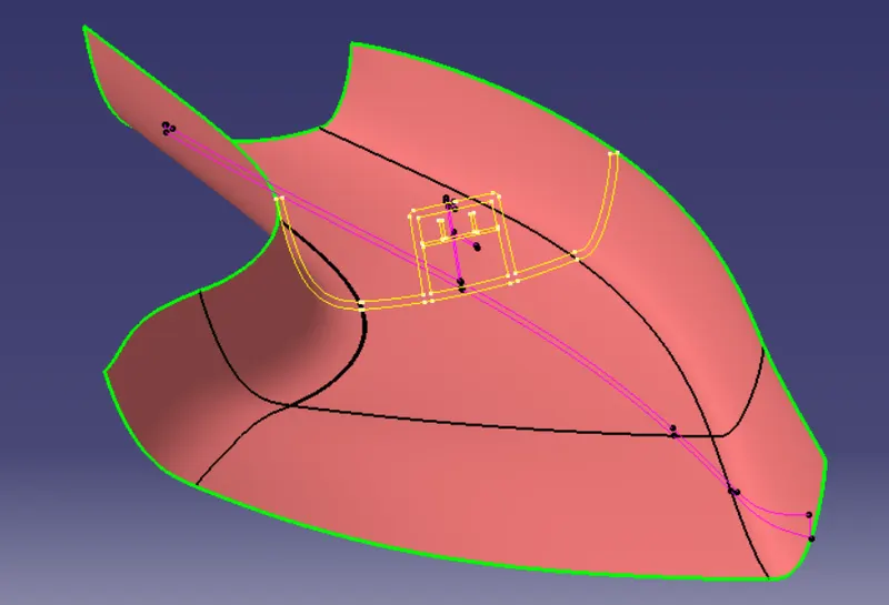

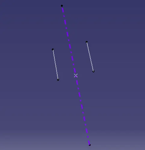
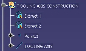
- Tooling Axis Construction : Since Master Sections is provided to us using which we have to create the desired A-Pillar Plastic Component, We'll use that Master Section by extracting the lines as shown below and create a Bisecting Line with respect to those extracted lines to create our Main Tooling Axis.
- Class B Construction : Offset it first for 2.5mm, after doing so, we find out that there is a big side patch in that surface.
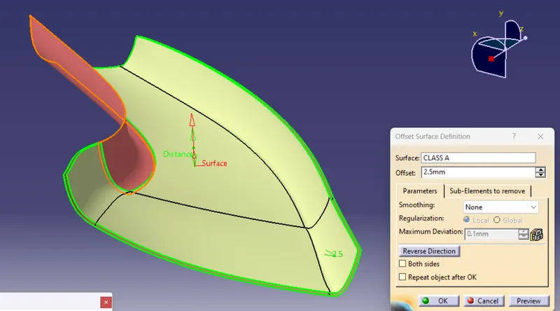
To cover this big patch, we performed the Sweep operation as shown in the below figure.
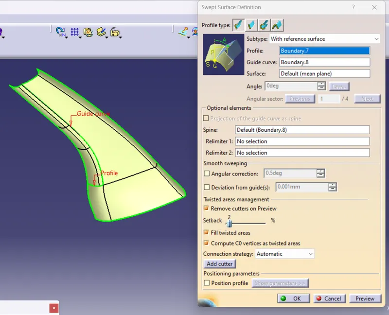
After sweep operation, we did the Joining of both surfaces with Join command and complete the B Class surface.
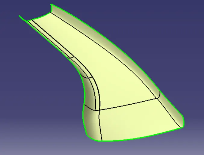
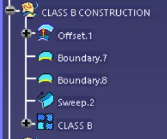
- Class C Construction : Class C surface is made by first unhiding Class A surface and by using Boundary command and Sweep Operation with reference surface, we created it.
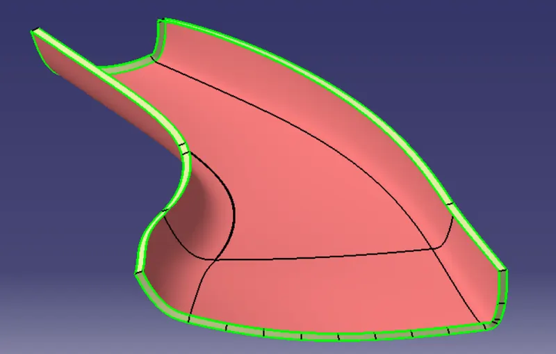
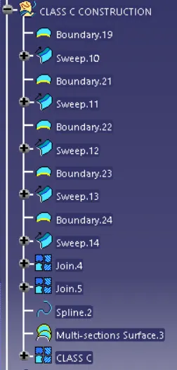
After finishing with Class C surface, we needed to join the Class A with Class C surface to have smooth surface between them.
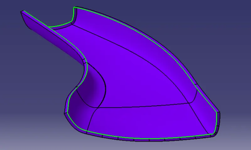
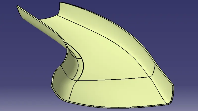
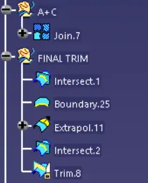
Then, after joining A with C, we did the Trim operation of A+C surface with B surface by extrapolating few parts of B surface so that the trim opreation can be performed smoothly.
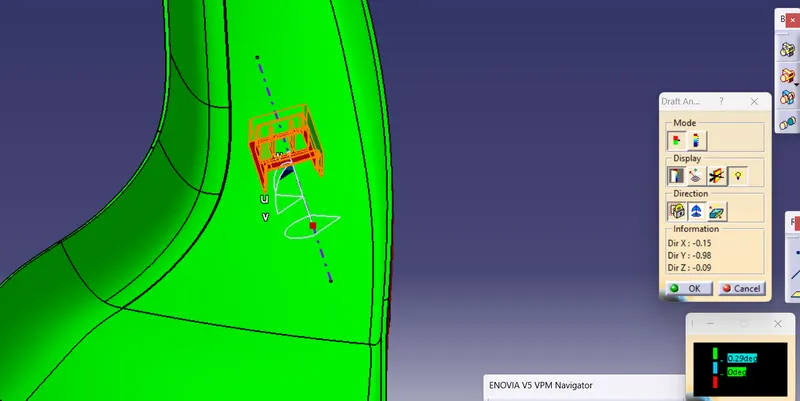
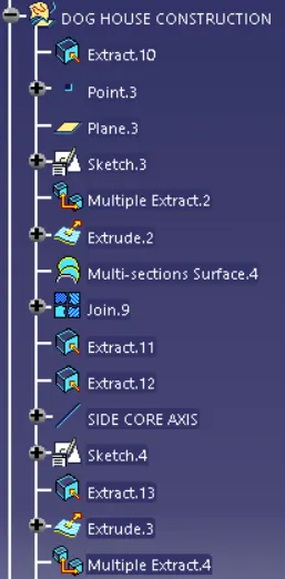
- Dog House Construction : Using the Master Section we can create a sketch that can be extruded to create the doghouse's walls. Using the Multi-Sections Surface command we're going to create the rear wall of the doghouse. Then, we'll join them all together and move on to the Part Workbench to thicken it. After that, we're going to provide all the required drafts using the 'Draft Angle' command in Part Workbench.
Draft Angle is provided at both the outer and inner sections of the doghouse with respect to the Main Tooling axis and Side-Core axis respectively.
Then, using the Master Section, we're going to create the inner walls of the doghouse. We've to provide the draft to these walls with respect to the Side-Core axis.
Provided the Edge-Fillet as found in the Master Section with a radius of 1.5mm.
To Create the CORING SECTION, firstly, we extracted the bottom surface of the main component and then offset it for around 4mm and then extract the inner walls of dog house with tangent continuity and offset it for around 1 mm. Now trim both the offset surfaces to make the coring section.
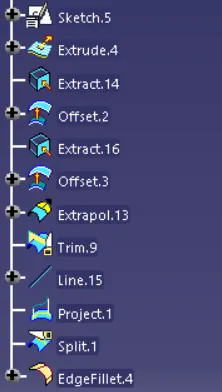
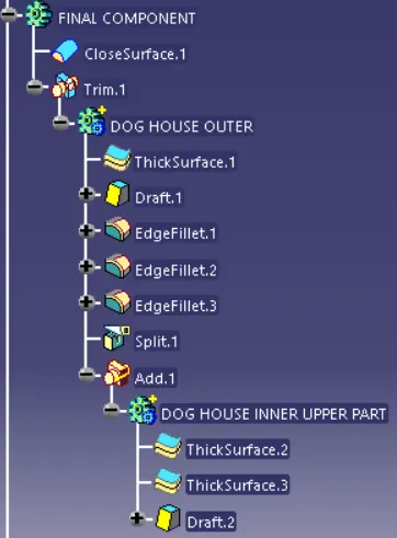
- Final Component : The main component without dog house, after final trim, we went to Part Workbench and chooses the Close Surface command to make it a solid body.
After that, we used the Thicken command to make the dog house a solid body.
Then, performed the Add and Union Trim operation to merge both the main component and dog house.

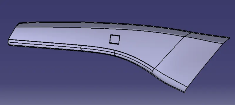
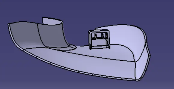
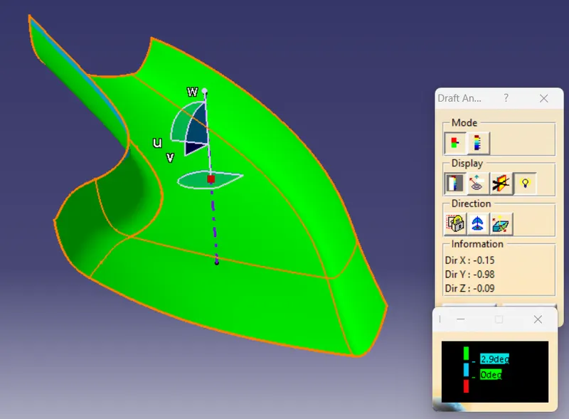
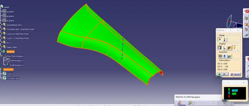
- Draft Analysis :
Class A Draft
Solid Body Draft
Dog House Draft
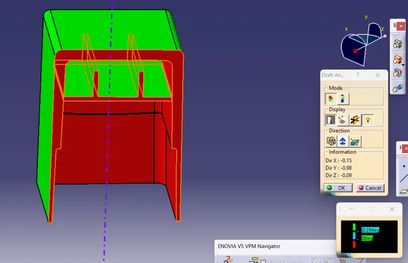
Final Component Draft