Week 11 - Project - A pillar Design with Master Section
AIM :-
To create a pillar Design with the help of Master Section, that is provided with the Cat file in the Classs A surface.
ABSTRACT :-
For the creation a pillar Design with the help of Master Section, that is provided with the Cat file in the Classs A surface, we need to maintained a proper features in mind that is neccesary to complete this work.
- Points to ensure:
- In Tree StructureEnsure using the surface command.
- Use closed body command to create the solids
- Rename the geometrical set properly.
- Output Required in a ppt :-
- Picture of the sketches with Sketch solving status’s geometry tab
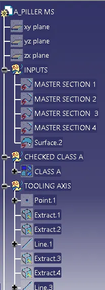
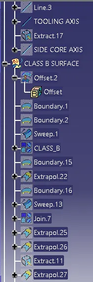
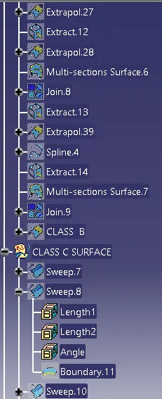
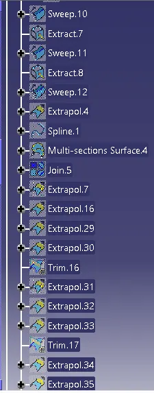
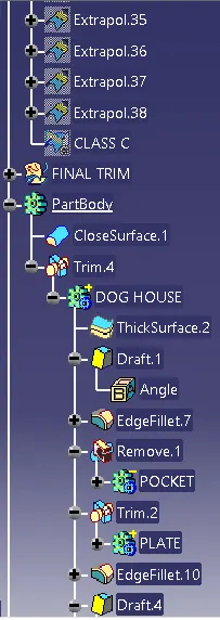
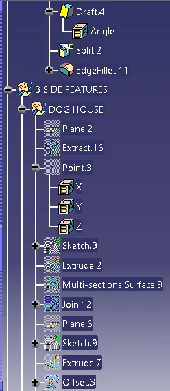
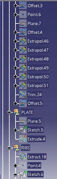
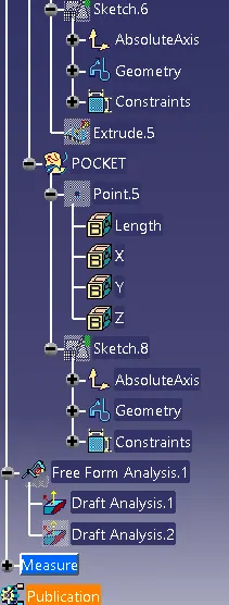
- Picture of the Detailed tree structure.
- Picture of the 3D CAD
- Create closed body
- Create a tooling axis and follow design rules.
- Follow the Master section to create a flange
- Follow the master section for thickness and to create the Closed volume.
- Follow the master section to create Attachment features
- The thickness of the Plastic to be 2.5 mm
SOLUTION :-
Master Section :-
- Master Sections are the guides for design requirements which shapes the component after technical styling of Class A Surfaces.
- Master sections are the guides for design requirements that decide the component packaging after technical (Styling, Concept, or Class-A) surfaces. Creating this master section should need 5 to 6 years of experience.
- This helps you to decide the feasibility, clearance, packaging, and fixation strategy before working it on a 3D. We have a master section.
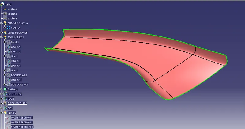
SNAP_1 :- Checked Class A with Boundary line.
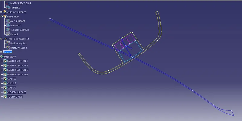
SNAP_2 :- Multiple master section
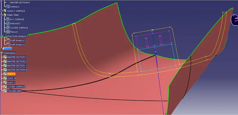
SNAP_3 :- Class A with Master sections
PROCEDURE_1 :- Creation of Tooling Axis
Tooling Axis :- In injection molding, the Class A surface is first analyzed to determine the axis or tooling direction that separates the molds. Tooling direction is critical for plastic product design because it determines mold direction. It is a main axis towards the direction the component ejject with also an core & cavity open or close.
The tooling axis created here with the reference of a master sections.
- First we need to create a point, point defination as a between.
- The point created between the 2 line point selected from the master section.
- After the point creation extract the 2 lines which are from the 1st master section. & hide the same master section as well for the better crearance view.
- Then this 2 lines has extraced used as a referance line for the creation the 1st Bisecting line.
- The same procedure are used for creation the another 2nd line from the 2nd master section repectively.
- Here we got a 2 Bisecting line in which we need to create a common line that is bisecting method again 7 finally we get a main Tooling axis.
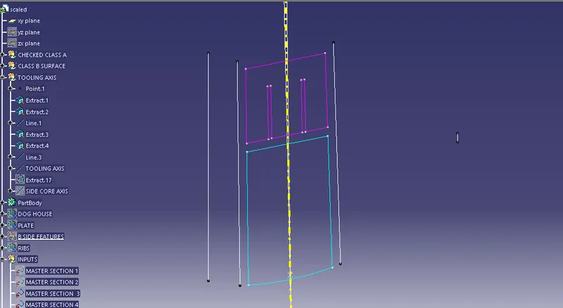
SNAP_4 :- Tooling Axis Created Yellow line as shown.
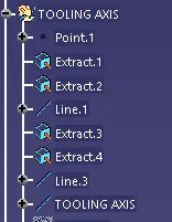
SNAP_5 :- Tooling Axis Related tree structure
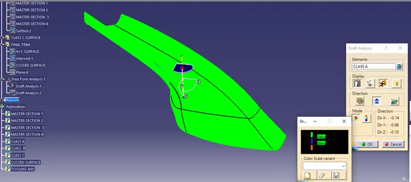
SNAP_6 :- Draft analysis of a class A
PROCEDURE_2 :- Creation of the Class B surface.
For creation the Class B surface we need to offset the Class A surface to the downward direction with the 2.5 mm .
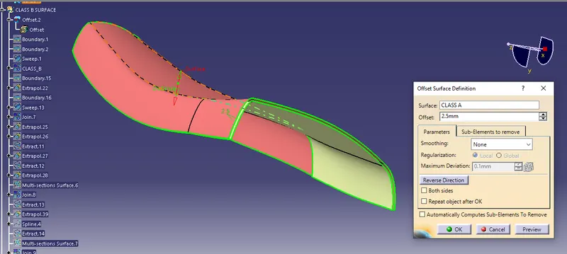
SNAP_7 :- Offset of class A
After offseting we got a uncleared surface the large cut/ patched surfaces has got.
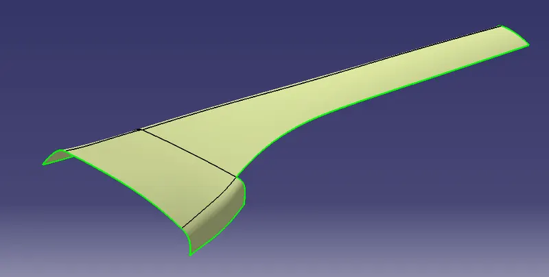
SNAP_8 :- Class B Patch area
so for the filling this patch / uncreared area we need to select a boundary with the adjecent corner of a offseted are & apply a sweep there.
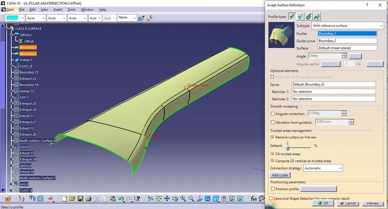
SNAP_9 :- Clear class B by applying sweep.
After that we need to select a join commond & select a offset & sweep together for getting a better class B surface.
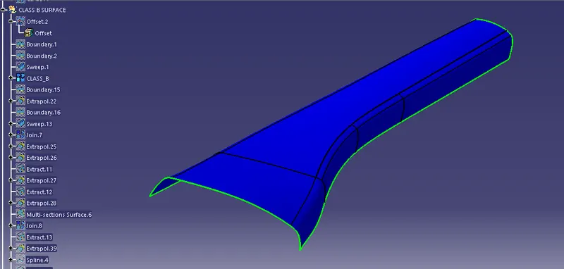
SNAP_10 :- Modified Class B
PROCEDURE_3 :- Creation of Class C surface
For the creation of Class C surface we need to take a multiple sweeps all over boundary line of the Class A
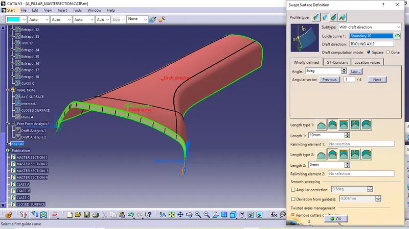
SNAP_11 :- Creation of Class C surface applying multiple sweep.
- In this procedure we need the Class A again to as a referance for creation the Class_C surface.
- Here 2 types of Sweeps are used for the making class_C surfaces.
- The 2 types as 1st is taking a referance surface with an angle of 90 Degree &
- 2nd is with the draft direction with the angle of 3 Degree. In the referance with surfaces we take a referance as a Class_A & in the with the draft direction as a Tooling axis as well.
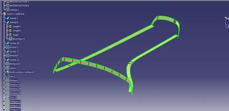
SNAP_12 :- Multiple sweeps of cass C surface
After the sweeps are applied there is need to trim the adjecent matting surfaces, so we need to extrapolate the proper extreme boundary line and apply the trim & finally join the trims together with an merging distance 0.003mm as well.
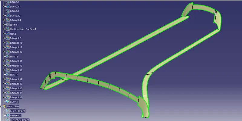
SNAP_13 :- Complete Class C surface
PROCEDURE_4 :- Final trim / Closed surface.
when we move on for getting the closed surface here we need to take a trim between the Class A + Class C or also we can join as well. After getting this trim we need to trim the Class B surface with the Class A+B . In this way we got a closed surface.
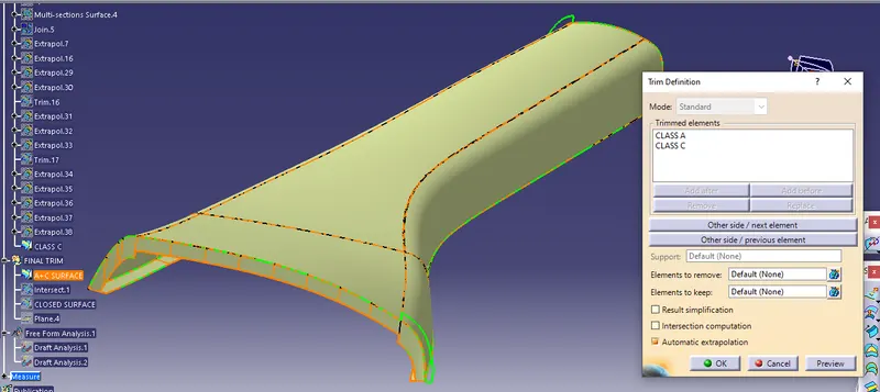
SNAP_14 :- Triming Class A with Class C
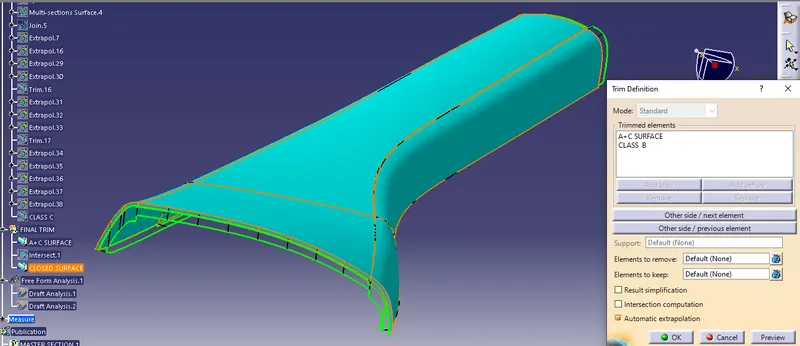
SNAP_15 :- Trimmed class A+C surface with Class B surface
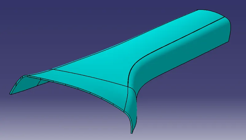
SNAP_16 :- Complete Closed surface
PROCEDURE_5 :- Closed Solid Body/ Final component.
After getting a closed surface, we need to insert a new body in the tree structure. First Switch the workbench into part design & select a command closed surface to make a solid body.
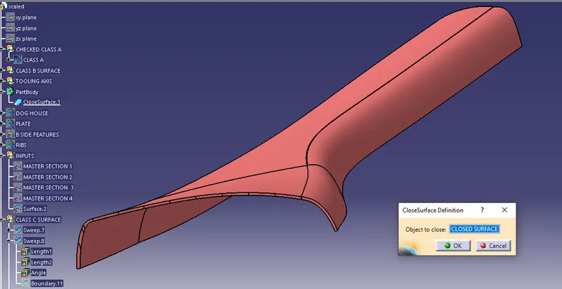
SNAP_17 :- Closed Body component
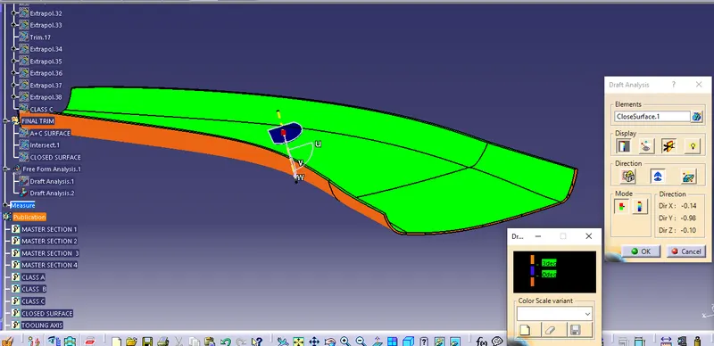
SNAP_18 :- Draft Analysis of a closed body component.
PROCEDURE_6 :- B_side feature creation.
1] Dog house creation
We always create a B side feature or a attachement by using the help of master section & make a sketch properly guidence with the master section. First create a mid-point between the 2 point of a 2 lines of a master section followed by the dog house section. Finally created a iso-constrained sketch as well.
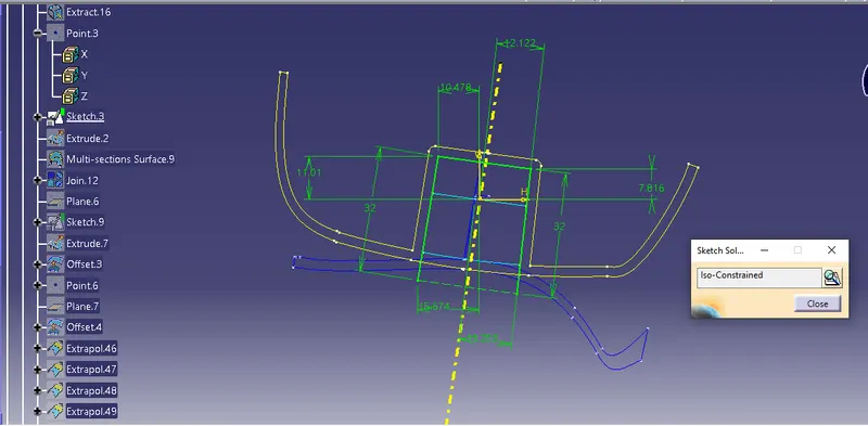
SNAP_19 :- Sketch of a Dog-House
2] PLATE :- In the same way the plate has created
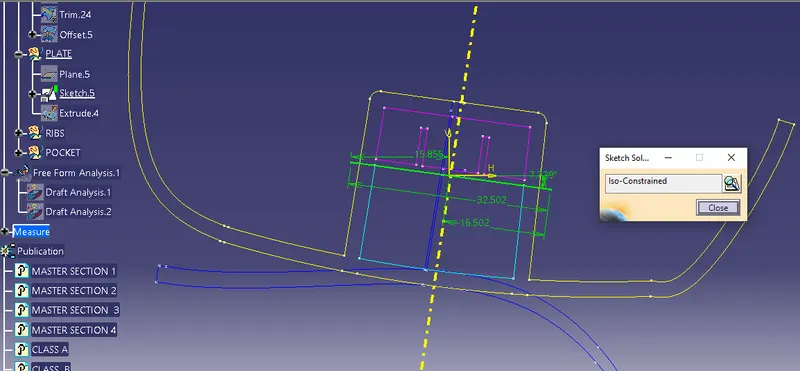
SNAP_20 :- Sketch of a plate
3] RIBS :- same way the Ribs also created with the help of master section.
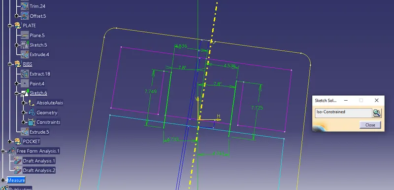
SNAP_21 :- Sketch of a Rib
4] Pocket :- The pocket has created at the top face of a dog-house with proper iso constrained.
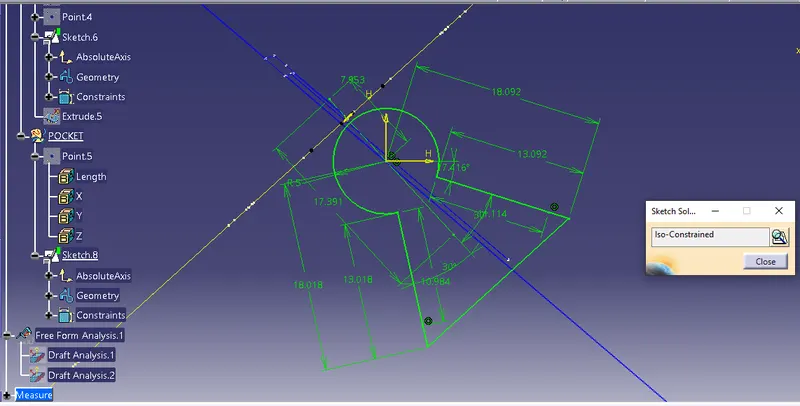
SNAP_22 :- Sketch of a Pocket
- After the sketches has make we need to pad or extrude it with proper thickeness has to be provided.
- In this way we have need to create the B-side feature dog-house inside sub elements of a Dog house as Plate,Ribs & pocket.
- The draft angle also has provided to inside the dog house is 0.5 with the referance of Tooling Axis & for the ribs & plate is 0.5 by the side core axis or lifter.
- Draft Angle Provided to the B side features & complete closed component.
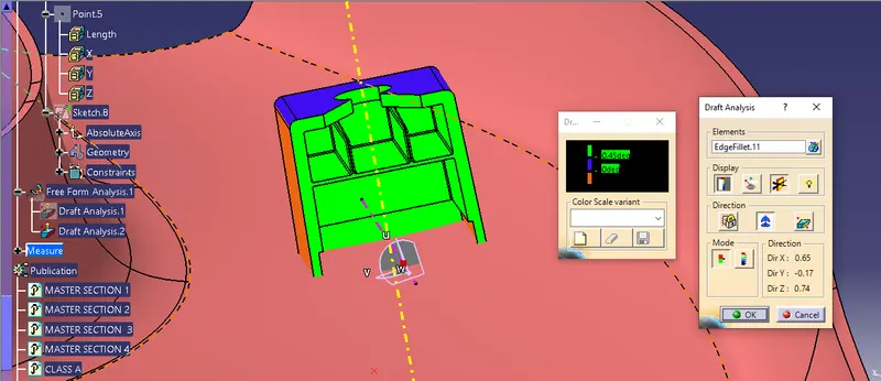
SNAP_23 :- A] Draft Analysis to the Dog house & inside attachement sub-elements
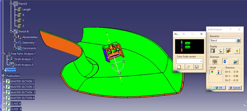
SNAP_24 :- B] Draft Analysis to the complete closed component.
- TREE STRUCTURE.
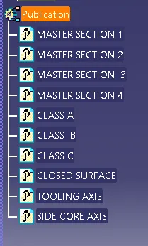
- FINAL COMPONENT WITH ALL VIEWS :
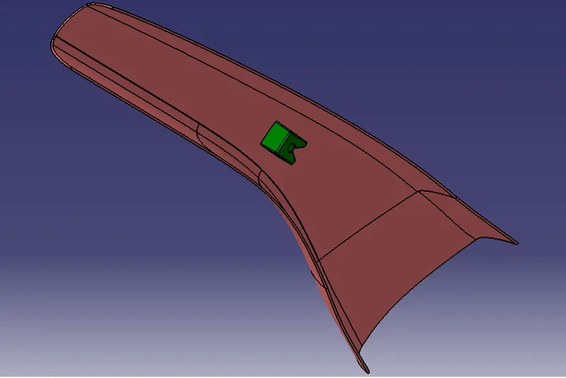
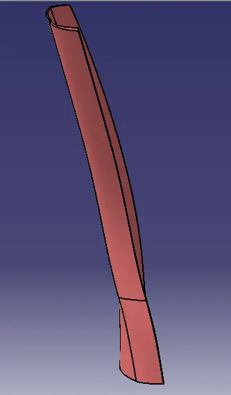
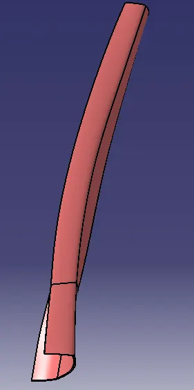
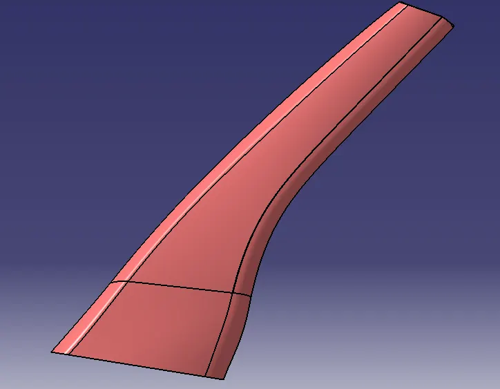
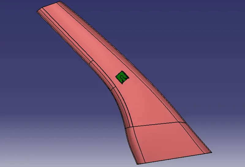
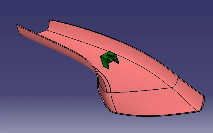
CONCLUSION :-
In this way we have cteated the closed body by the provided Class A surface. After this we have Created the B-side feature with the help of master sections as well. The required snaps are attached to the report & Explained each steps respectively. Finally Cat part file is also browse.
Thank You.