Week 11 - Project - A pillar Design with Master Section
ANSWERS
INTRODUCTION
The B-Pillar is the car's central pillar. In reality, this pillar is a sheet metal component that is welded into the car's body. The B-Pillar Trim, which is affixed to the B-Pillar and enhances the car's aesthetic appeal. The Injection Moulding Process Is Generally Used To Produce The Trims. The B-Pillar's design is thoughtfully done to allow for manufacturing and interior use. A lot of flaws can appear on the plastic component during injection moulding, destroying the panel's aesthetic appeal. The design must be created in a way that allows for the correction of all errors.
STAGES OF DESIGN CYCLE
CONCEPT SKETCHES
Concept sketches will be used to prepare the model and are rough ideas of free-hand sketches obtained from the styling team. Typically, it is accomplished with a pen and paper as well as painting software. This will be used to develop the idea for creating the model by incorporating different approaches and data gathered from the stakeholders.
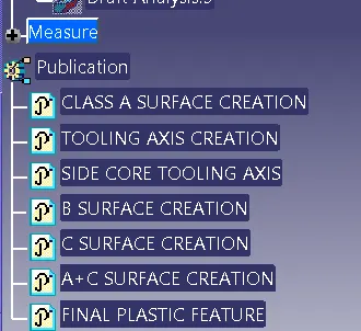
CLASS A CREATION
After Finalizing The Concept The Sketches Are Usually Worked In Software’s Such As Auto-Desk Alias To Create Class A Surface
CLAY MODELLING
The New Product Design (Npd) Cad is prepared by the design team while the Class A Surface is being simultaneously worked on by clay modellers to brainstorm and benchmark the styling of the product. Afterward, the concept is validated by bringing up a rough clay model.
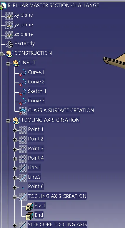
TOOLING AXIS CREATION
In order to imagine the item to be manufactured, the Class A input is analysed. The tooling axis, tooling direction, or die line is the direction in which moulds pull apart during injection moulding. Core and Cavity are the names of the two mould components. As a result, tooling direction affects mould separation and is crucial for creating plastic products that are drafted to the desired nominal angle for easy clearance and part ejection from the mould.
- A new axis system and reference point are established along Surface Zero.
- To create the tooling direction, the X and Y directions along the Class A were used.
- After creating the tooling axis by dividing the two lines, it is published. Utilising Surface Operation Commands with Class A Surface as Input The development of Class B
- The Class C Boundary Swept With Draught Direction Is Determined By The Tooling Axis.
- When looking from the tooling direction normally, all the drafted parts should be visible to provide a general idea of how the product will be manufactured in injection moulding.
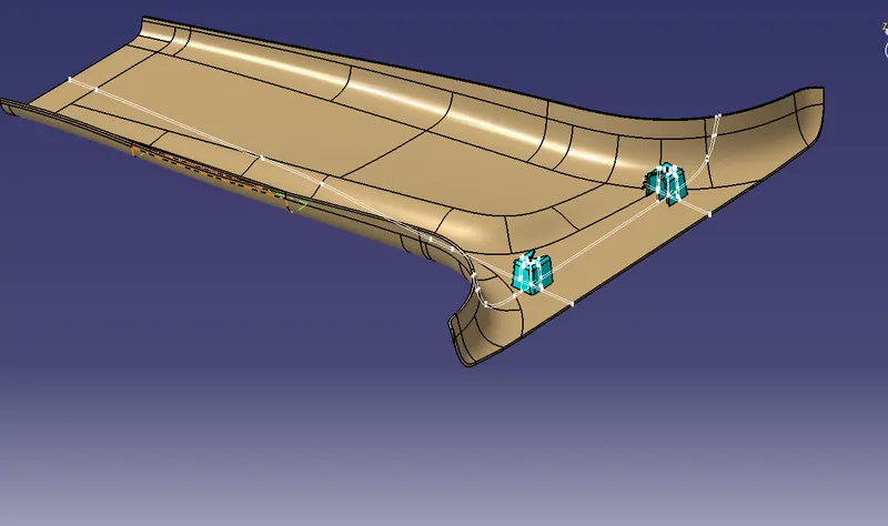
- Two tooling directions—one on the main tooling and the other on the lifter side—are present in the B-Pillar Model and are utilised to eject the parts during injection moulding.
- Because the attachment feature is enclosed by close walls, lifter axis is used.
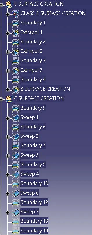
CLASS SURFACE B CREATION
Surface Operations in Catia are used to create the B surface, which is an offset from Class A with dimensions proportional to the part thickness.
In B Pillar Design, the B Surface Is Offset 2mm From The Input, Which Is The Part's Thickness As Defined By The Mastersection.
CLASS SURFACE C CREATION
-
The boundary line for Class A, which is the guide curve with a subtype along draught direction, is used to sweep the C Surface.
-
The Tooling Direction Established Earlier Is The Sweep's Direction.
-
A 3 degree draught angle is provided for the sweep operation, and the surface is swept for a length above the specified part's thickness.
-
To avoid the parting line along the A surface, the C surfaces must be drafted outward from the A side.
-
The complexity and patches along the swept surface are removed from the C surface using smooth curve options.
-
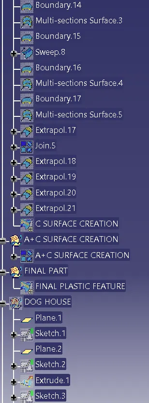
Finally, the Class A and Class C Surfaces are merged, and the concentricity of the surfaces should be less than 0.003 mm.
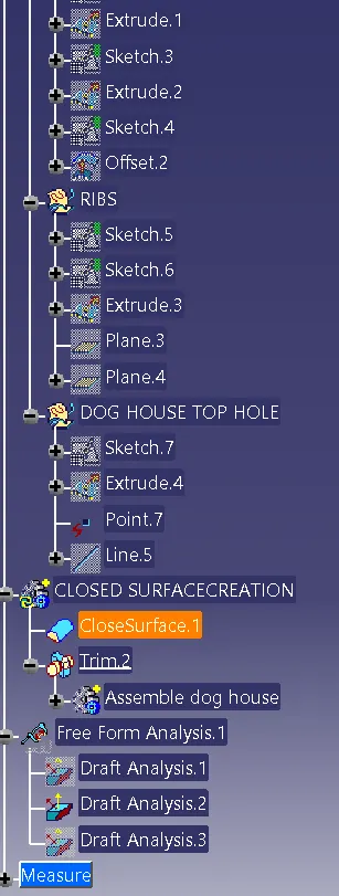
DOG HOUSE
- The doghouse is made using the master section, and the thickness option is then used to model the part.
- In order to locate the B pillar in the direction of the mating surfaces, the 4 Way Locator is formed above the dog house.
- The Rules for Dog House Design
- The Connecting Surface Thickness Should Be 40% Off The Main Thickness On The B Side
- At least 0.5 degrees are drafted into the walls in the main tooling direction.
- A lifter axis is used since the attachment feature created requires a separate tooling axis to clear the part.
TREE STRUCTURE