Week 11: Project 2 - Emission characterization on a CAT3410 engine
Aim :
Emission characterization on CAT3410 engine using ConvergeCFD.
Objective :
Simulate with both open W and Omega pistons.
Explain the simulation setup.
Characterize the emissions(Soot,NOx and UHC).
Create animations showing the variation of all the engine parameters.
Compare the indicated mean effective pressure and power values graphically.
Introduction and Theory :
Diesel Engines -
Compressing any gas raises its temperature, the method by which fuel is ignited in diesel engines. Air is drawn into the cylinders and is compressed by the pistons at compression ratios as high as 25:1, much higher than used for spark-ignite engines. At near the end of the compression stroke, diesel fuel is injected into the combustion chamber through an injector (or atomizer). The fuel ignites from contact with the air that, due to compression, has been heated to a temperature of about 700–900 Celsius (°C) (1300–1650 Farenheit (°F)). The resulting combustion causes increased heat and expansion in the cylinder which increases pressure and moves the piston downward. A connecting rod transmits this motion to a crankshaft
to convert linear motion to rotary motion for use as power in a variety of applications.
Surface Preparation In Converge -
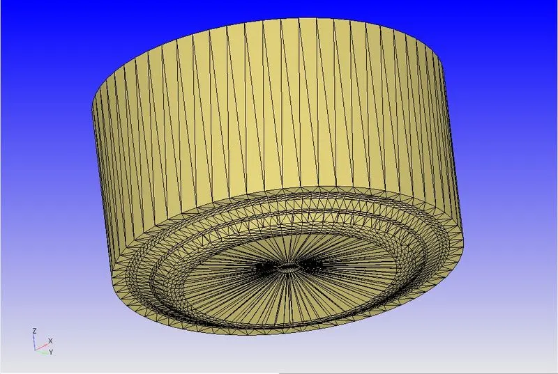
The 'make engine sector surface' option in converge helps in surface preparation.Now to understand sector surface lets first look at the given geometry.The geometry depicts the close engine cylinder(combustion chamber),where entire piston top surface,cylinder liner,and cylinder head is present.But we do not have any valves,intake or exhaust ports.This is what one can
call as a close cycle analysis,because we are doing all the analysis when valves are closed. This is done in order to increase computational efficiency.For the diesel engine,most probably the injector is mounted at the center of the cylinder headand the injector is going to have multiple nozzles.
Now to increase the computational efficiency,we can consider one sector of the concerned domain, in this case it is combustion chamber,and simulate the combustion in it.The obvious advantage of this method is that,we will require way less computational cells and simulation run time will be faster.This is where 'make engine sector surface' option comes into play.It can be found in Tools => Make engine sector surface.
To make sector we need combustion chamber specifications and piston profile.And getting a piston profile is very hard.To simplify this task converge provides Extract profille option.The idea to get the profile is that,we cut the combustion chamber with a plane and we will get it's profile on a plane and then we can get the piston profile.
In this project simulation was performed using two types of piston heads,one with open-W and another one with Omega piston head,profile images of which are shown below.After the simulation, the performance and emission parameters are compared for both types.
Solution Procedure :
To perform this simulation ,we will follow the below procedure :-
Engine Sector Creation --> Case Setup --> Solution --> Post Processing
Engine Sector Creation :
To create engine sector follow the below procedure,
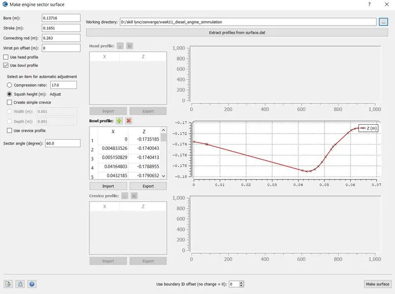
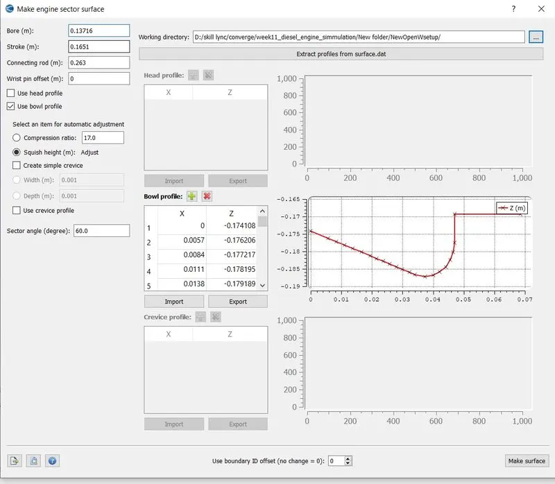
Tools => Make engine sector surface => Extract profiles from surface.dat => Select open_W_piston_360.dat => Extract.
This will create bowl profile for open-W piston.Now we need to import the this bowl profile,but before that we need to specify bore,stroke,connecting rod parameters.Also define compression ratio and and sector angle in degrees which is 60 degrees in this case.Also make sure to turn on use bowl profile option. Now click on import under bowl profile window select the generated bowl profile and click on make surface.
Case Setup :
Engine Specifications -
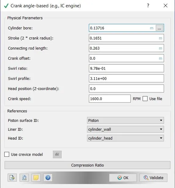
First select the crank angle base simulation and specify the engine parameters such as cylinder bore,stroke,connecting rod length crank speed and proper reference surface IDs for piston, liner and head.
Parcel Simmulation -
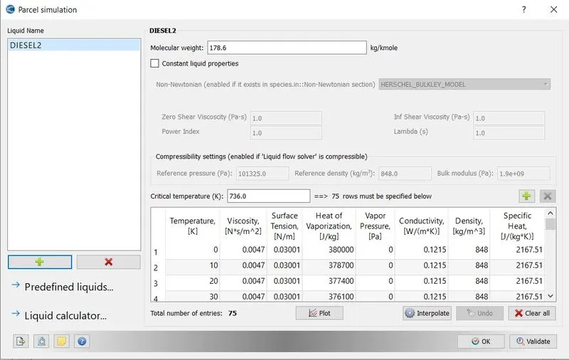
Selected the proper fuel parcel,with which we want to simulate the simualtion.In this case select DIESEL2.Parcel Simulation => Predefined Liquids => select DIESEL2 => Add selected.
Here we are selecting DIESEL2 ,because it has properties very close to DIESEL.If we were to use gasolene fuel then, we would have to select IC8H18_Isooctane.Physical properties of fuel used in experiments must match with the physical properties of parcel species we are using.
Species Definition -
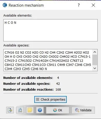
In materials select reaction mechanism.Feed the mech.dat file data into the reaction mechanism setup.The reaction mechanism setup reads all the species data from the mech.dat file and shows it in the available species box.
Species Definition(For Parcel) -
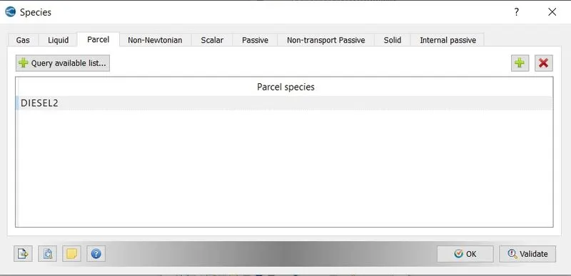
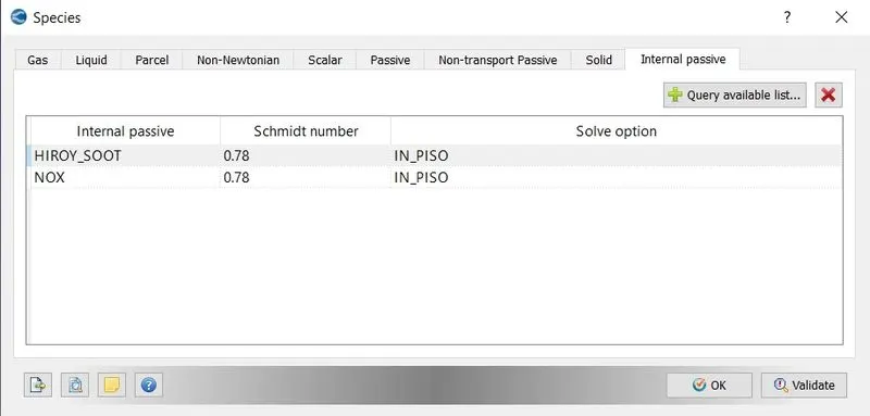
Now,in the species section ,the selected parcel species was defined,Here,we do not need to define all the species that we are using,as we have already defined them in the reaction mechanism.We only have to define the liquid species from the parcel species.
Run Parameters -
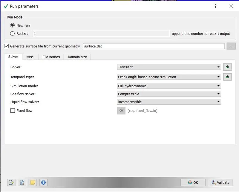
In run parameters select transient solver and Full hyderodynamic solver as simulation mode,since combustion is happening in this simulation.And, as the air and vaporization of diesel is involved,set gas flow solver to compressible and liquid flow solver to incompressible.
Simulation Time Paramaters -
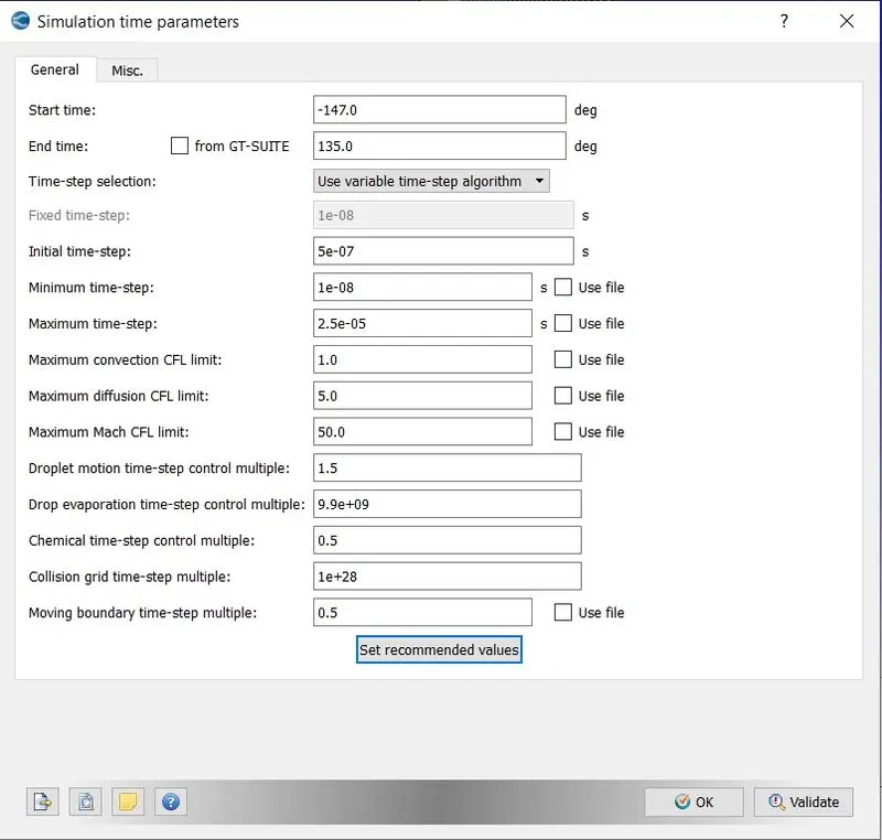
Give proper simiulation time parameters.Define the start and end crank angles.
Boundary Conditions -
Piston -
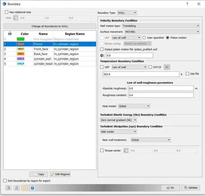
The piston wall surface is the moving surface,specifically the translating surface.Thus select wall motion type as translating , with surface movement as moving and law of the wall.Make sure to select the piston motion option,other wise piston won't move in the simulation.
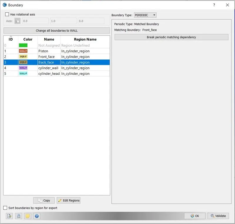
Front Face -
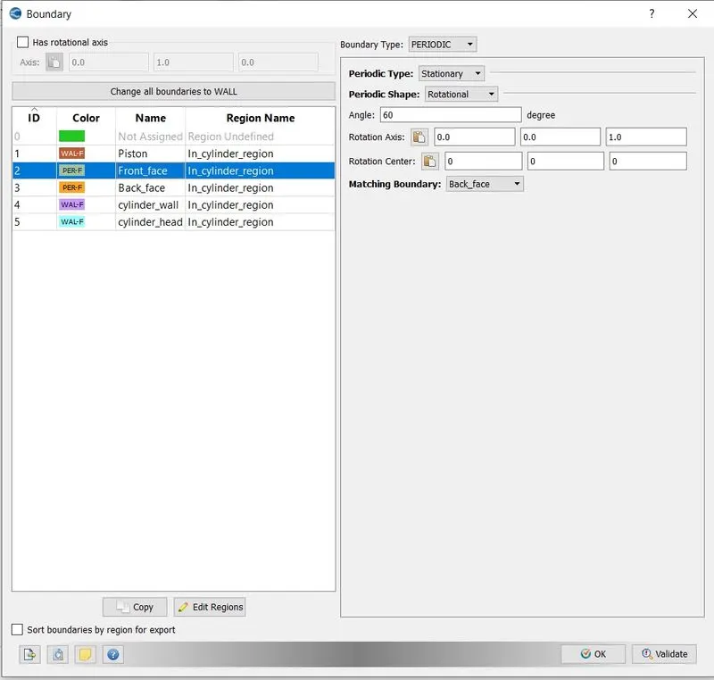
It is that surface,from which sector part of the combustion chamber is cut out.So we have two of those surfaces -front and back . As we have created the engine sector surface with angle 60 degrees, make sure to select periodic angle 60 degrees.
Back Face -
By using the matching boundary option in one surface we can provide the same boundary conditions to other surface,in this case it is back face.
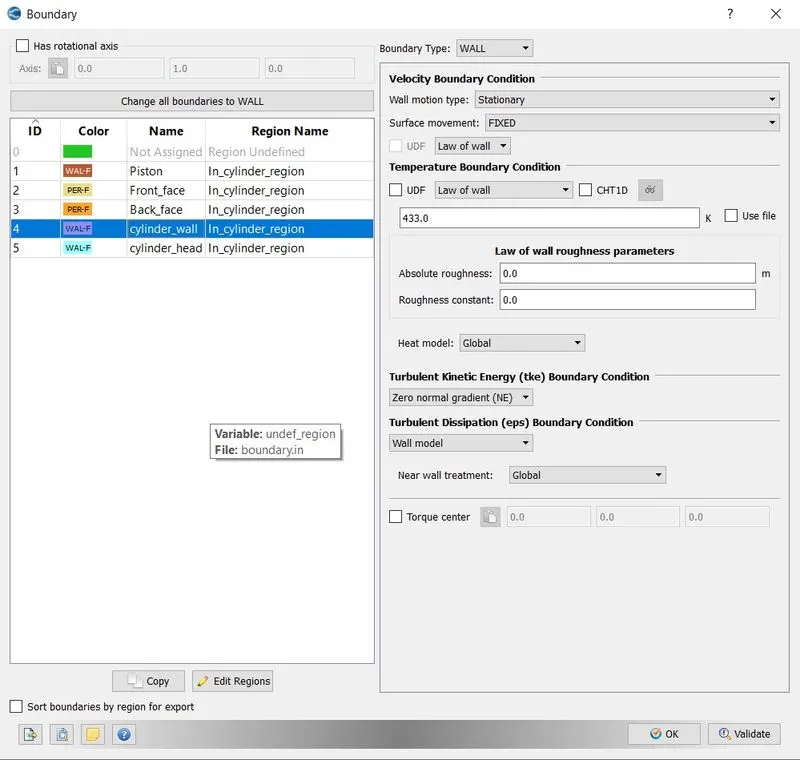
Cylinder Wall -
The cylinder wall will stay stationary throughout the simulation,thus only the working temperature is provided to the setup.
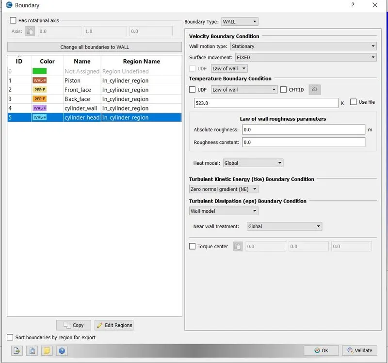
Cylinder Head -
Also,cylinder head will be stationary ,thus only the working temperature is provided,which will be higher than cylinder wall.
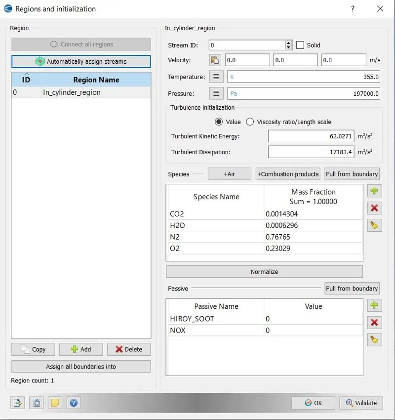
Regions Definition And Initialization -
Spray Modelling -
General -
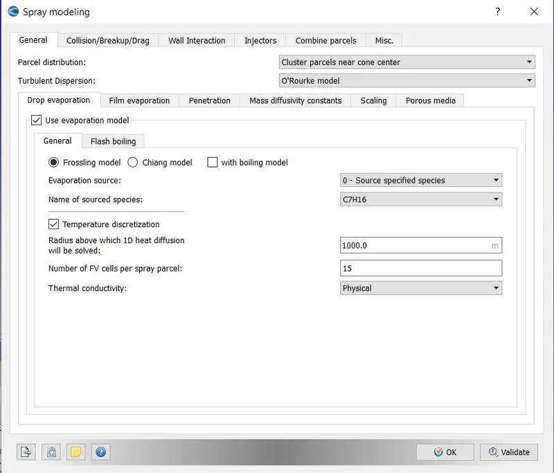
Unless specifically mentioned always select distribute parcels evenly throughout cone.As we have turbulence in our gas phase , these turbulence fluctuations are going to affect droplet characteristics.For diesel sprays O'Rourke model has been shown to give better performance. We have selected frossling model as evaporation model,which helps to dictate the rate at which our parcel radius is going to change.Source specified species selected as evaporation source.
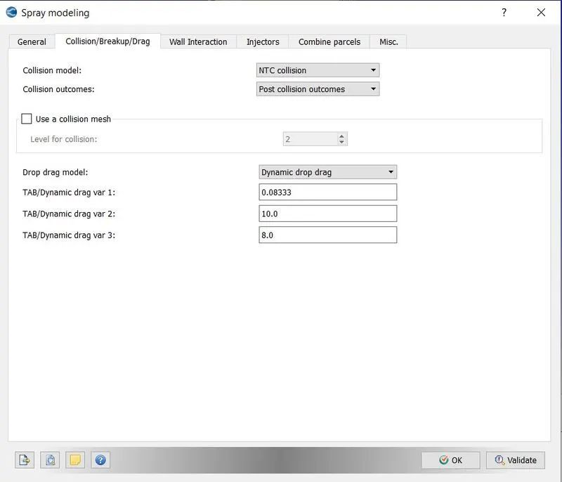
Typically our fuel parcel is sphere.Outside of the sphere is hotter than the inside of the sphere.Typically a parcel is made up of drops that have only one temperature and there is no difference in the temperature.We can discretize the droplets by creating spherical finite volume cells.And solve the heat equation ODE on all of those individual finite volume cells. Although this process is more accurate ,it's time consuming.
When drop size is very very small,assuming that the entire drop is at the same temperature is more reasonable.And if drop is big,then there is going to be a gradient in temperature inside the drop.The maximum radius for ODE droplet heating is the cut off radius,above that radius ODE is solved and below that radius ODE isn't solved.Here we are putting larger value ,that means our ODE is never going to be solved and this will make our simulation run faster.Here we are sacrificing accuracy which is fine , because we don't have experimental data.
Injection Configuration -
To configure the injection parameters add the injector in the injectors section.
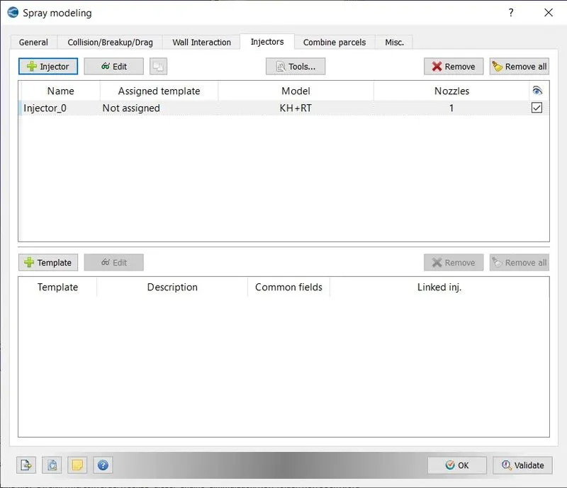
Injector Species and Rate Shape -
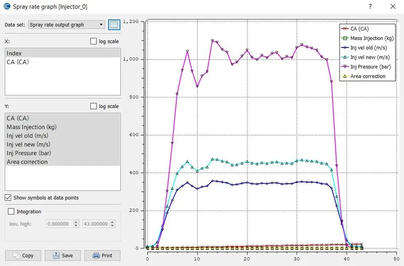
In the injected species we told converge what species are being injected.In injection rate shape, converge will take the total mass of the fluid that we have provided and the total duration that we have provided and it will use this profile to inject that mass accordingly within the time that we have specified.
Spray Rate Graph -
The following picture shows,how the injection rate of the fuel change with the crank angle.
Models -
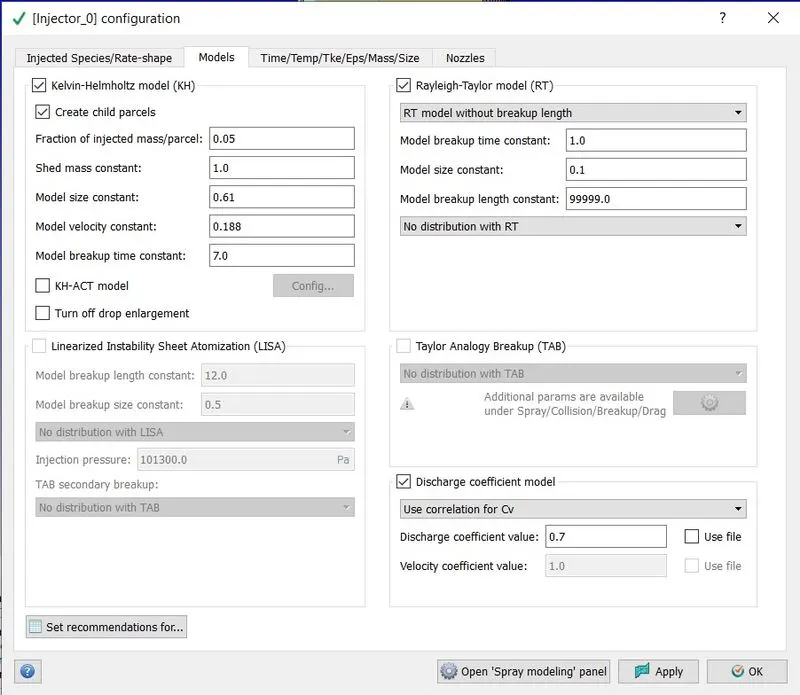
Kevin Helmhotz and Rayleigh Taylor,these are the models that are used for solid cone sprays , it does not matter if it's diesel and gasolene.For traditional port fuel injector,tumble DI injector,DI diesel it's all going to be solid cone.
We can see there are some constants,these controls how our parcel is going to break up.There is an equation known as stability or dispersion equation which says how long it is going to take for disturbances on a perticular parcel to go unstable . With this equation we can come up with a logical time scale.But this equation is derived in a very simple manner,so we
would have to put some constants so that we can increase or decrease the time it takes for the breakup to occur and also increase or decrease the size of the child.When Kevin Helmholtz model predicts the size of the child drop,we multiply the drop value by input value(here 0.6) which is model size constant and reduce it.
Time/Temp/Mass/Size -
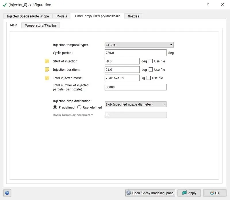
Following parameters were set for time/temp/mass/size option.
Nozzle Location And Orientation -
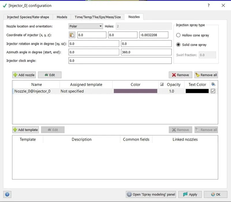
We have provided the below parameters,so that we can have our injector in the center of the cylinder. Also provided geometrical parameters for nozzle.
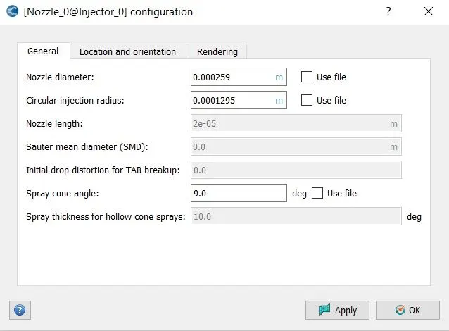

When we are specifying the nozzle,it can not be outside the geometry,hence follow the below steps,
spray modelling => Injectors => Tools => Validate Nozzle Locations => It should display the message as 'All nozzles are inside the computational domain'.
Combustion Modelling -
Combustion facilitataes the energy transfer in the engine.Converge contains a detailed chemistry solver and simplified combustion models .In this project SAGE model is used which solves detailed chemmical kinetics.SAGE calculates the elementary reaction rate while CFD solves the transport equation.
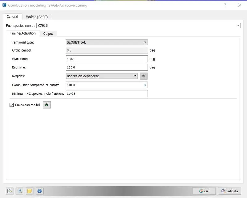
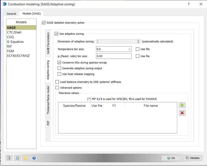
CONVERGE contains the SAGE detailed chemical kinetics solver, which models detailed chemical kinetics via a set of CHEMKIN-formatted input files. To solve the systems of ordinary differential equations (ODEs), SAGE uses the CVODE solver.
A chemical reaction mechanism is a set of elementary reactions that describe an overall chemical reaction. The combustion of different fuels can be modeled by changing the mechanism (e.g., there are mechanisms for isooctane, gasoline, n-heptane, natural gas, etc.).
Given an accurate mechanism, SAGE (in addition to AMR) can be used for modeling many combustion regimes (ignition , premixed , mixing-controlled).We can use SAGE to model either constant-volume or constant-pressure combustion.
Emission Modelling -
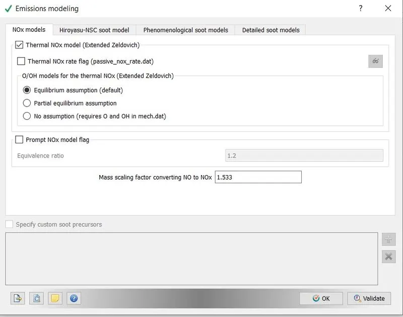
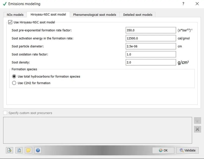
As the main objective of this project to discuss emission parameters for both types of pistons, it is necessary to setup proper emission models.
Turbulence Model -
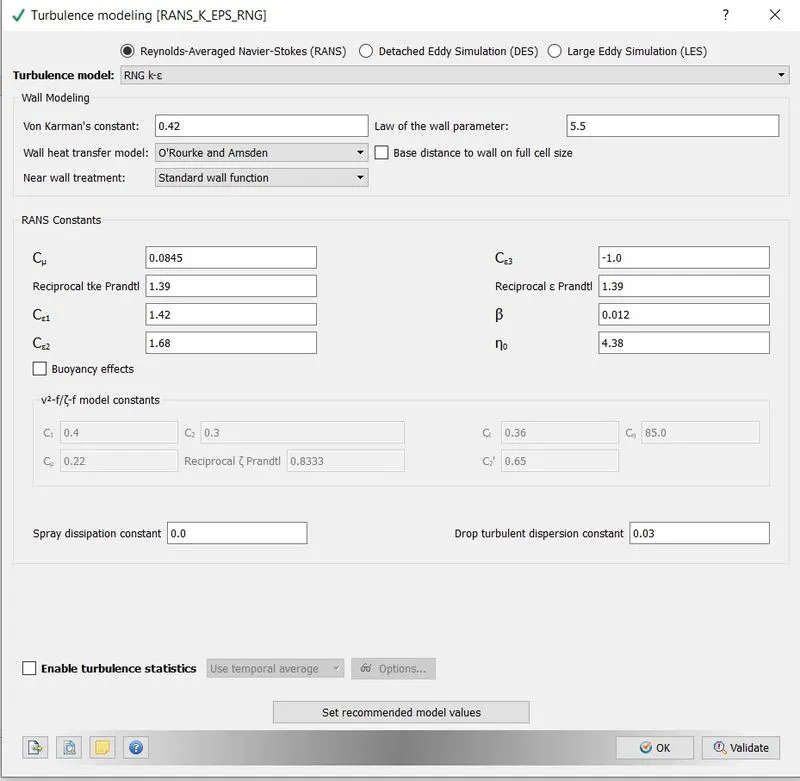
We have chose RNG k-e model as turbulence model.
Base Grid-
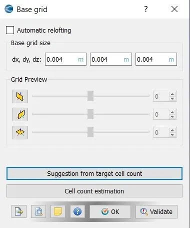
In converge mesh generation is a fully automatic process.Converge uses cut cell method to generate the mesh.This is a patented method developed by coverge.
Adaptive Mesh Refinement -
To accurately capture the important physics of the injection process,we need high resolution grid around the spray.However we do not need high refinement far away from the injector or before the fuel spray. Adaptive Mesh Refinement (AMR) automatically refines the grid based on fluctuating and moving conditions such as temperature or velocity.AMR is used to obtain a refined grid in flow regions of interest allowing complex phenomena, such as flame propagation or high-velocity
flow, without unnecessarily slowing the simulation with a globally refined grid.
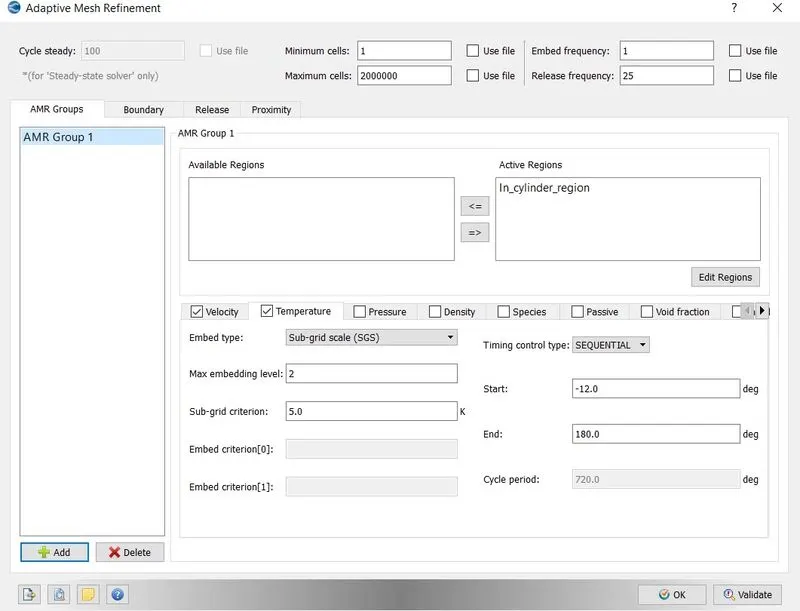
Now we want to moniter how the flow properties changes as the combustion starts.We will moniter temperature deviation inside the cylinder.For that we will do the adaptive mesh refinement based on temperature deviation.We need to provide sub grid criterion.So whenever subgrid scale temperature difference is greater than user specified value our mesh will refine.
Velocity SGS -
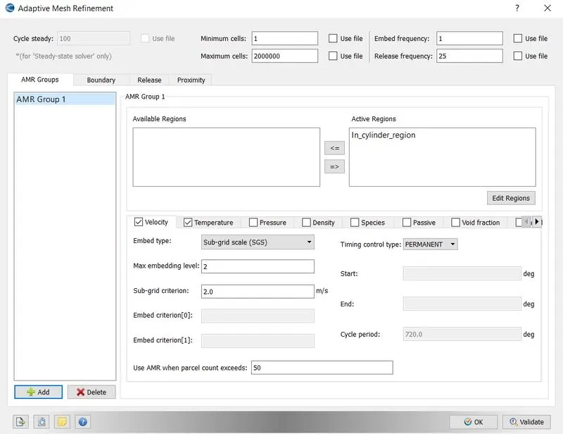
Temperature SGS -
Fixed Embedding -
Why do we need this refinement ?
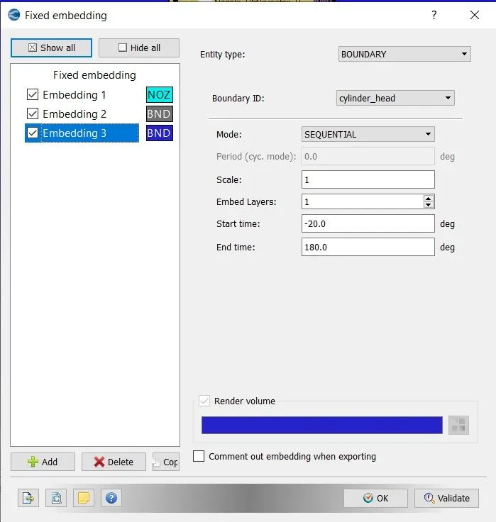
We will be using temperature AMR so that based upon curvature in the temperature field, cells will be refined.But when the spark is initially introduced ,just at that instant we don't have good refinement so that these gradience can be calculated accurately.So we are initially creating highly refined regions which lasts only for few crank angles,so that after some time,after
one or two time steps the temperature AMR is able to see that there is huge gradient or huge curvature change in temperature near the spark and then it's going to workout. In other words this initial set of refinements is used to provide a better seed value for our AMR calculations.If the grid is very coarse the curvature values will also be low and AMR might not do anything about it.
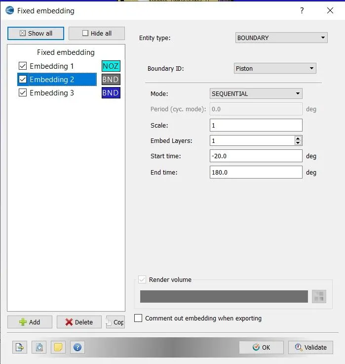
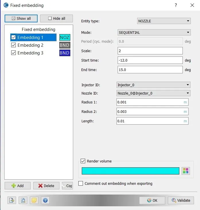
To refine the mesh near the walls and at different regions we will provide the fixed embedding. We can see how the mesh is being refined after the spray injection in mesh animation.
Output Files -
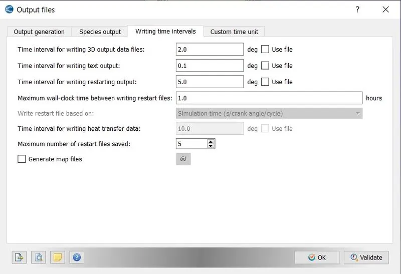
The 3D output file will be generated after every 2 degrees of rotation of the crankshaft.
Timing Map -
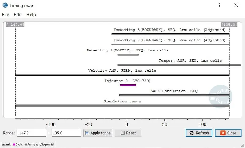
The timing map is like a pathway that lays out all simulation timing details into something like a processs chart which displays specified timing for the specific process.This map is important to validate that above setup is correct.
Solution :
For running the simulation,first we need to export all the input files to the folder where we want to save our output files,
File => Export => Export Input Files => select the desired folder => Export.
Now we will use CYGWIN command prompt to run our simulation.But before running the simulation first we need executables
which willl solve the simulation,for that paste mpiexec.exe and converge.exe into the folder where we have exported all our input files.
Now using CYGWIN command prompt,navigate to the folder where all the input files are exported,and type the below command ,
mpiexec.exe -n 4 converge.exe restricted </dev/null> logfile &
In the above command ,mpiexec.exe will help us to run our simulation in parallel,-n 4 are the number of cores on which we
want to run our simulation.As we are using the version of converge which has limit on the size of the file it can solve hence the command restricted.And the last part of the command dump all the data that is being generated into the logfile, which we can access during simulation procedure to see where our simulation has reached.
The above command will create a folder named output containing all the generated 3D output data.As we will be using paraview as the postprocessing tool.Hence we need to convert these output files into the format that paraview can read.For this we will use converge post convert tool.
Go to converge post processing 3D =>give case name => select the file type => navigate to the output folder and select it
=> select all files => select all variables => convert.
This will create group file ,which will be used by paraview to post process our results.
Post-Processing And Results :
Compression Ratio -
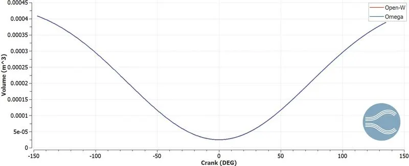
Compression ratio helps in determining the thermal efficiency of the given engine.As higher compression ratio results in higher pressure and temperature, which in turn produces more output power and torque.By comparing the compression ratio we can clearly see that omega piston has higher compression ratio thus producing more pressure and temperature which will be validate in the plots shown below.
A] Compression Ratio for Open-W piston :
Max.Volume = `0.0004086 m^3`
Min.Volume = `2.5405e^-05`
`"Compression Ratio" = "(Max.Volume)"/"(Min.Volume)"`
`"Compression Ratio" = 0.0004086/(2.5405*e^-05)`
`"Compression Ratio" = 16.0834`
B] Compression Ratio for Omega piston :
`"Max.Volume" = 0.0004078m^3`
`"Min.Volume "= 2.4635e^-05`
`"Compression Ratio" = "(Max.Volume)"/"(Min.Volume)"`
`"Compression Ratio" = 0.0004078/(2.4635*e^-05)`
`"Compression Ratio" = 16.5536`
Pressure Variation -
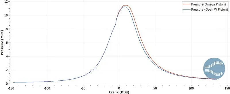
The below is the chart showing the pressure variation inside the combustion chamber during compression and expansion stroke.At the expansion or combustion stroke,high pressure is generating, which is where engine power is generated.
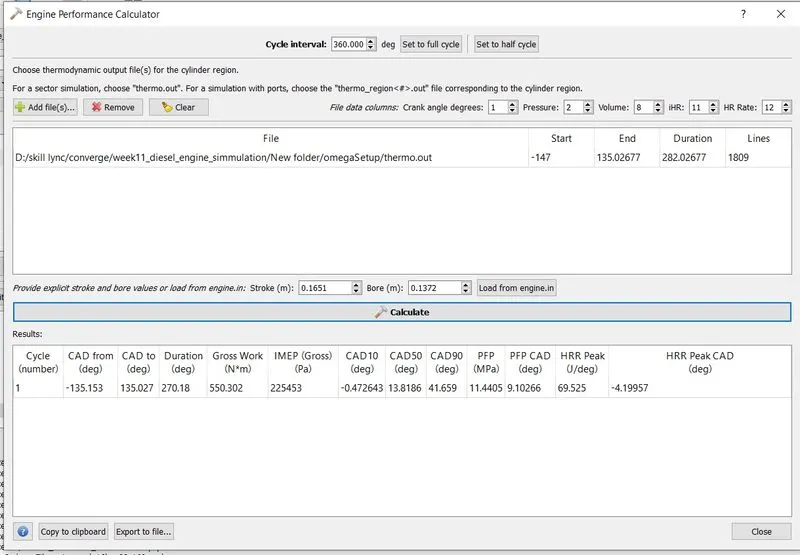
The peak pressure is 11.44 MPa and 11.22 MPa for Omega and Open-W piston respectively.Pressure generation for both the pistons is nearly the same until compression stroke,but as fuel(diesel) starts to burn pressure rise slightly more in omega piston.Also delayed pressure drop is observed in case of omega piston.
Temperature Variation -
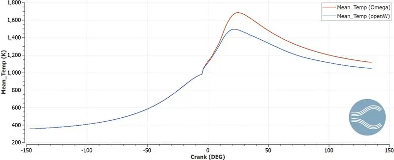
From the graph,it can clearly seen that omega type achieves higher temperature than open-W,which in tune with pressure variation chart.This means better fuel combustion is happening in omega piston type combustion chamber than open-W.This results in less unburnt hydrocarbons in omega type piston than open-W.
Heat Release Rate -
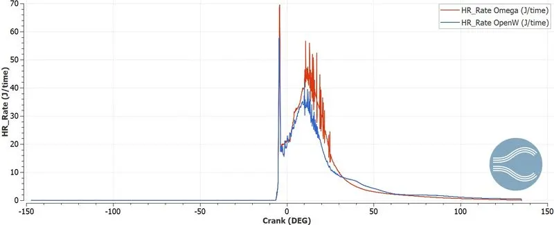
This tells us how the heat is being released as a function of crank angle. As we observed from temperature variation plot , omega type piston achieves higher temperature than open-W type.Therefore heat release rate of omega piston is also higher.
Also we can observe as the spray starts before the 0 degree angle,the diesel liquid drops vaporize and starts to ignite which gives sudden heat release rate near 0 degree crank angle.Then after that as the diesel vapors defuse in the air the heat rate gradually starts to increase towards the peak point and after expansion begins to decrease.
Integrated Heat Release Rate (IHR)-
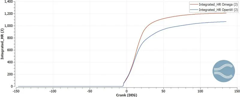
IHR gives us idea about the combustion efficiency.IHR is a integral quantity.Basically we take heat release curve and integrate it.This tells at any given moment how much energy is being released from combustion alone.
From the plot we can see that in open-W type piston combustion is bit slower and at the end we are getting different energy output for the same fuel.The above heat release profile well in line with the temperature profile,where the temperature of omega piston was higher leading to a much higher heat release.
Gaseous Fuel Mass -
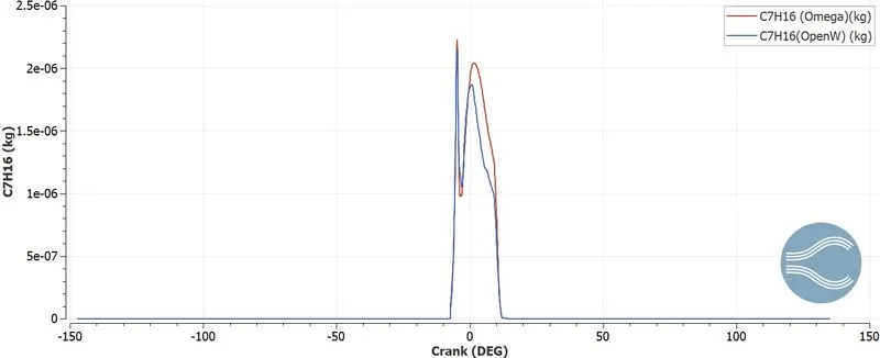
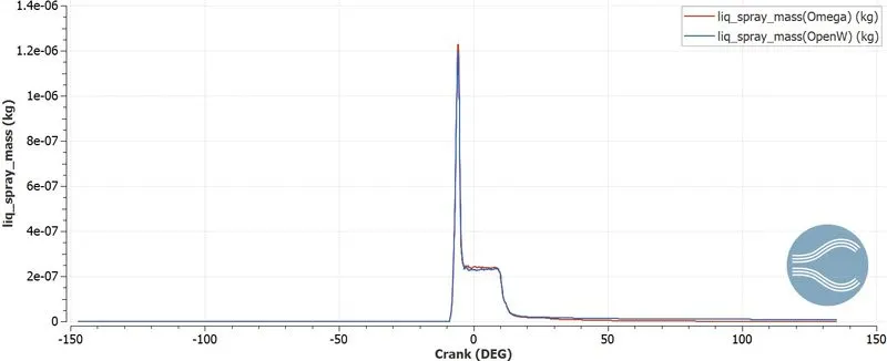
There is significant amount of gaseous fuel in omega piston than open-W piston.This is specifically due to the piston design.As fuel penetration length is longer in omega piston compared to open-W piston,causing more fuel evaporation inside the omega piston type combustion chamber.While in open-W piston lot of fuel impingement occurs causing less vapor formation,yet combustion takes place due to higher pressure and temperature.Also omega type piston causes swirl formation inside the combustion chamber which results in better air fuel mixing and vaporization leading to better fuel combustion.Thus open=W piston results in having lower efficiency,torque and power.
Emission Characterization -
NOx-
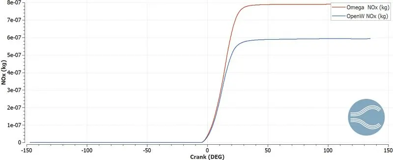
NOx is formed due to higher combustion temprature.And this is evedent from the below plot,where omega type piston has higher NOx formation,as it achives higher combustion chamber than open-W piston.
Carbon Monooxide(CO) -
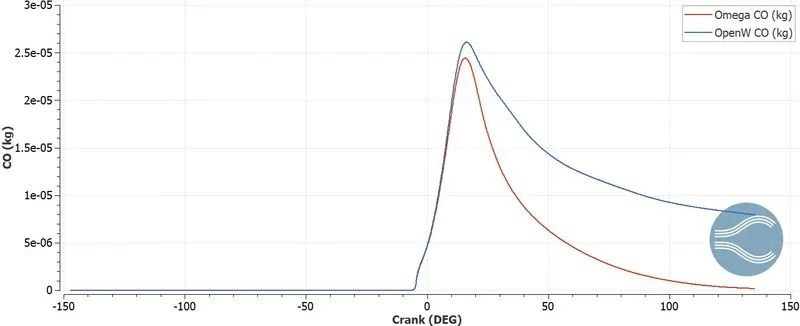
It is caused by incomplete combustion and poor air fuel mixing.As omega piston has longer spray penetration length and also better air fuel mixing due to swirl formation,it causes less CO formation when compared with open-W piston.Open-W has higher presense of unburnt fuel,less peak pressure and temperature all leading to higher CO formation.
Hiroy Soot-
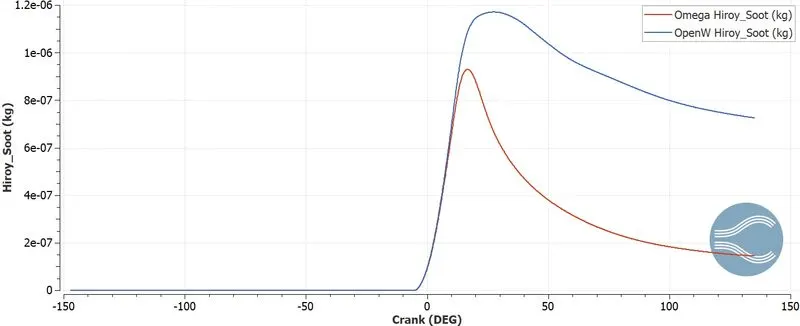
This is mainly caused by unburnt fuel inside the combustion chamber.We can observe that as soon as the combuston starts soot formation increases significantly inside the combustion chamber housing open-W type piston.This due to lower combustion temperature,less fuel vaporization,poor air fuel mixing resulting lot of residual formation as compared to omega piston.
Carbon Dioxide(CO2) -
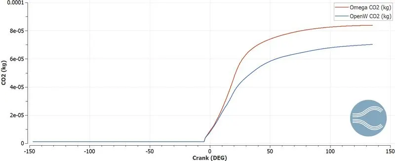
Carbon dioxide forms due to combustion of fuel.So it is obvious that better the combustion more the CO2.This can be seen in the plot as omega piston has higher CO2 formation due to better combustion as compared to open-W piston.
HydroCarbon(HC) -
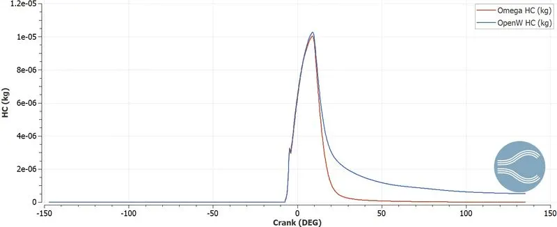
Hydrocarbons are present in the fuel.They form because of escape from combustion process.From the plot we observe that, at the start of the spray amount of hydrocarbon in same for both pistons, then after combustion there is sudden decrease in hydrocarbon for omega piston,whereas for open-W piston it is more gradual.This is due to higher combustion temperature for omega piston which results in proper hydrocarbon burning than open-W piston.
Engine Performance Calculator -
Combustion Chamber With Omega Type Piston -
Combustion Chamber With Open-W Type Piston -
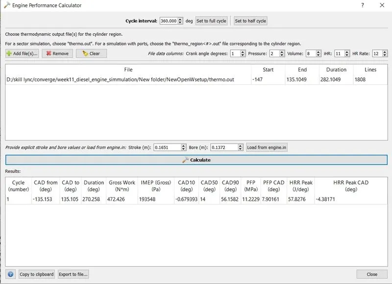
Now observing above data we can clearly see discrepancies in many parameters for both types of piston.Let's compare them,
Power -
For Open-W,
`"Net Power = Work/Time" = 472.426/(0.02815*1000) = 16.782 KW`
For Omega,
`"Net Power = Work/Time" = 550.302/(0.02815*1000) = 19.548 KW`
Torque -
For Open-W,
`"Power" = (2*pi*N*T)/60`
`T =(P*1000*60)/(2*pi*N)`
`T= (16.782*60*1000)/(2*pi*1600) = 100.210 Nm`
For Omega,
`T= (19.548*60*1000)/(2*pi*1600) = 107.80 Nm`
| Open-W | Omega | |
| Total Gross Work (Nm) | 472.426 | 550.302 |
| IMEP(Gross)(Pa) | 193548 | 225453 |
| Duration of cycle in deg | 270.258 | 270.18 |
| RPM | 1600 | 1600 |
| RPS | 26.67 | 26.67 |
| Time for rotation of each degree(sec) | 1.04E-04 | 1.04E-04 |
| Number of cycles in every minutes(60/time for each cycle) | 0.02815 | 0.02815 |
| Net Power(Work/time)(KW) | 16.782 | 19.548 |
| Torque | 100.210 | 107.80 |
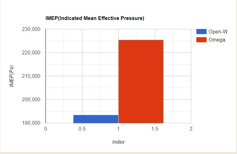
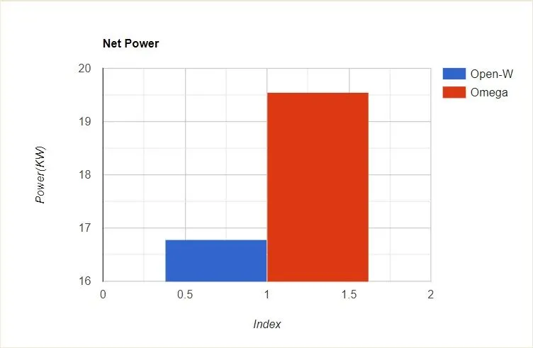
We can conclude that we are getting maximum power output and higher indicated mean effective pressure with the Omega type piston.Thus Omega piston has higher performance than the Open-W piston.
Animations :
Mass Fraction of NOx -https://www.youtube.com/watch?v=8iouzfQFcE0
Mass Fraction of CO -https://www.youtube.com/watch?v=5_doSFnPJuk
Mass Fraction of C7H16 -https://www.youtube.com/watch?v=EAN6lZb2XBU
Mass Fraction of CO2 -https://www.youtube.com/watch?v=yoAQUUt1m_c
Mesh Generation -https://www.youtube.com/watch?v=E9w4L784mMo
Flame Propagation - 1.https://www.youtube.com/watch?v=ntk80ZH1t14
2.https://www.youtube.com/watch?v=tirRd49Vv_M
Spray Injection -https://www.youtube.com/watch?v=RE74Inrs-nk
Soot Formation - https://www.youtube.com/watch?v=fbHWyi9-SsY
Unburnt Hydrocarbons - 1.https://www.youtube.com/watch?v=SjUNyp3J8rc
2. https://www.youtube.com/watch?v=GBL1m5HIun0
Conclusion :
Upon observation we can conclude that combustion chamber with Omega type piston shows better atomization and vaporization than open=W piston,thus producing more torque and power than open-W.
Also Omega type piston has less presence of hydrocarbons compared to open-W piston,indicating better combustion,thus producing less soot and carbon monooxide.
As combustion temperature is higher in Omega type piston,it is prducing more NOx and CO2.
Overall if we observe all the parameters omega piston is better in terms of power output and efficient and also produces less emissions as compared to Open-W piston.Thus cylinder with Omega type piston is a better overall choice in this project.