Week 11: Project 2 - Emission characterization on a CAT3410 engine
AIM
To run simulations with omega and open-w pistons and characterize the emissions
THEORY
Diesel engine
The diesel engine, named after Rudolf Diesel, is an internal combustion engine in which ignition of the fuel is caused by the elevated temperature of the air in the cylinder due to mechanical compression; thus, the diesel engine is a so-called compression-ignition engine (CI engine). This contrasts with engines using spark plug-ignition of the air-fuel mixture, such as a petrol engine (gasoline engine) or a gas engine (using a gaseous fuel like natural gas or liquefied petroleum gas). Diesel engines work by compressing only air, or air plus residual combustion gases from the exhaust known as exhaust gas recirculation (EGR) is inducted into the chamber during the intake stroke, and compressed during the compression stroke. This increases the air temperature inside the cylinder to such a high degree that atomised diesel fuel injected into the combustion chamber ignites. With the fuel being injected into the air just before combustion, the dispersion of the fuel is uneven; this is called a heterogeneous air-fuel mixture. The torque a diesel engine produces is controlled by manipulating the air-fuel ratio; instead of throttling the intake air, the diesel engine relies on altering the amount of fuel that is injected, and the air-fuel ratio is usually high.
The diesel engine has the highest thermal efficiency (engine efficiency) of any practical internal or external combustion engine due to its very high expansion ratio and inherent lean burn which enables heat dissipation by the excess air. A small efficiency loss is also avoided compared with non-direct-injection gasoline engines since unburned fuel is not present during valve overlap and therefore no fuel goes directly from the intake/injection to the exhaust.
The characteristics of a diesel engine are:
- Compression ignition: Due to almost adiabatic compression, the fuel ignites without any ignition-initiating apparatus such as spark plugs.
- Mixture formation inside the combustion chamber: Air and fuel are mixed in the combustion chamber and not in the inlet manifold.
- Torque adjustment solely by mixture quality: Instead of throttling the air-fuel mixture, the amount of torque produced is set solely by the mass of injected fuel, always mixed with as much air as possible.
- Heterogeneous air-fuel mixture: The dispersion of air and fuel in the combustion chamber is uneven.
- High air ratio: Due to always running on as much air as possible and not depending on exact mixture of air and fuel, diesel engines have an air-fuel ratio leaner than stochiometric.
- Diffusion flame: At combustion, oxygen first has to diffuse into the flame, rather than having oxygen and fuel already mixed before combustion, which would result in a premixed flame.
- Fuel with high ignition performance: As diesel engines solely rely on compression ignition, fuel with high ignition performance (cetane rating) is ideal for proper engine operation, fuel with a good knocking resistance (octane rating), e.g. petrol, is suboptimal for diesel engines.
SIMULATION PROCEDURE
- Setting up the case in converge
- Running the simulation in cygwin
- Post convert using cygwin/converge
- Post processing in paraview
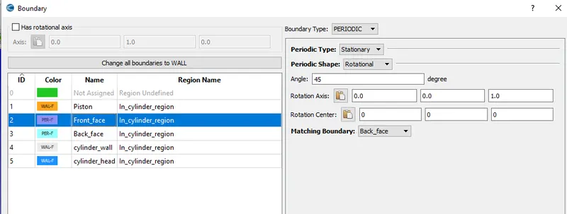
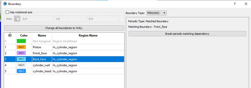
- The simulation is performed only on a sector of the geometry for computational efficiency.
- Make engine sector surface tool is used to create a sector model from a `360^0` geomtery.
- The profile shapes are extracted from the `360^0` geometry.
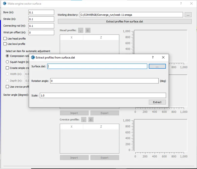
- After creating the profiles, open the same toolbox then enter the dimensions of bore, stroke and connecting rod.
- Enter the compression ratio value and sector angle then import the bowl profile and extract the sector surface.
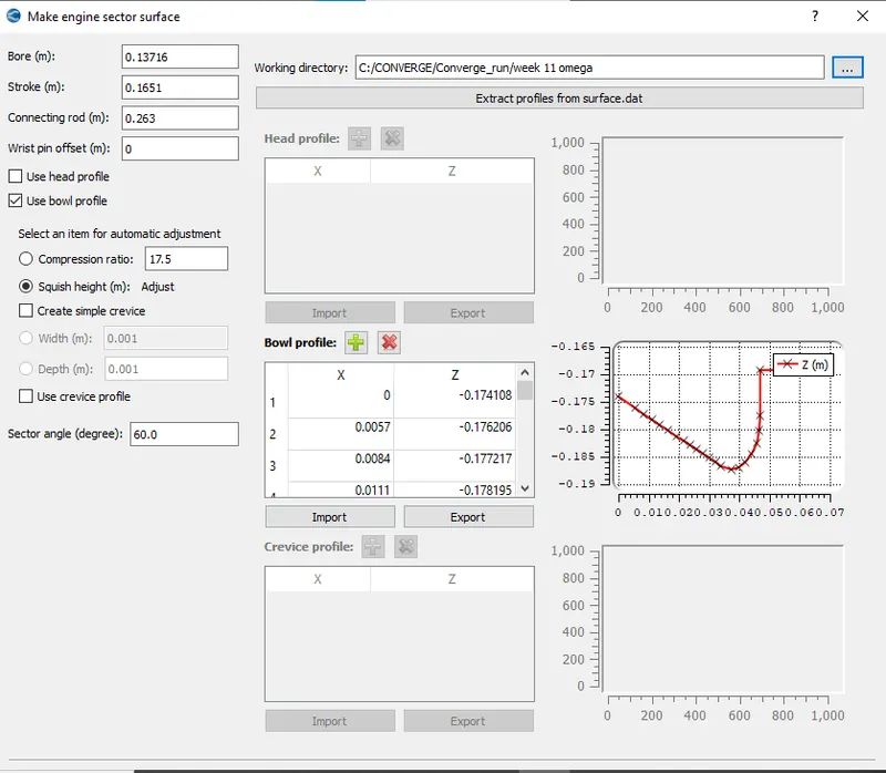
- Using this method the sector surfaces of open-w and omega piston are developed.
- Then the boundaries are flagged. The next step is case setup.
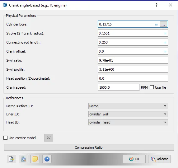
- Crank angle based simulation is selected, since diesel engine is to be simulated.
- The physical parameters are entered as given below:
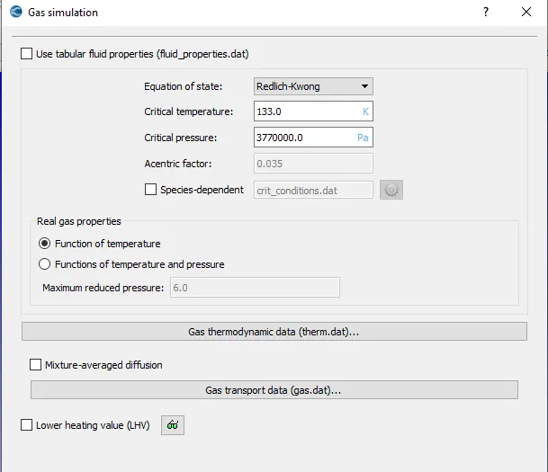
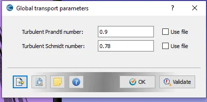
- In gas simulation import the therm.dat and gas.dat files. The default options are retained in gas simulation and global transport properties.
Materials
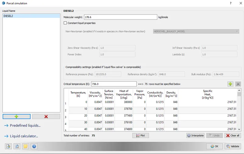
- Diesel is used as the fuel. Add DIESEL2 in the parcel simulation.
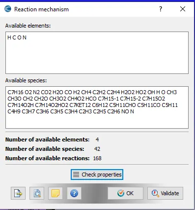
- In reaction mechanism upload the mech.dat file.
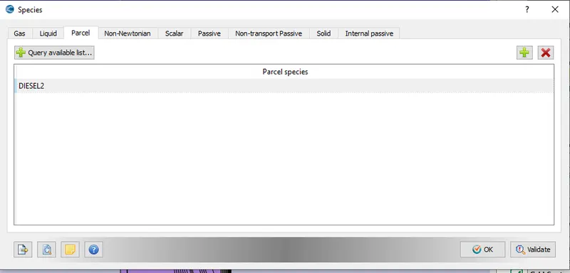
- Add DIESEL2 in the parcel option in species.
- In run parameters, a transient based solver with full hydrodynamic mode is selected.
- In solver parameters, density based Navier stokes solver is selected.
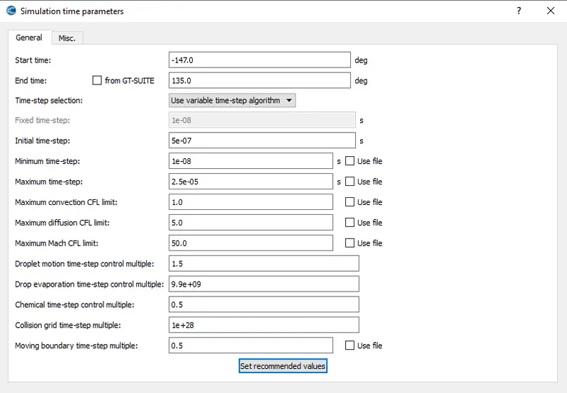
Simulation time parameters
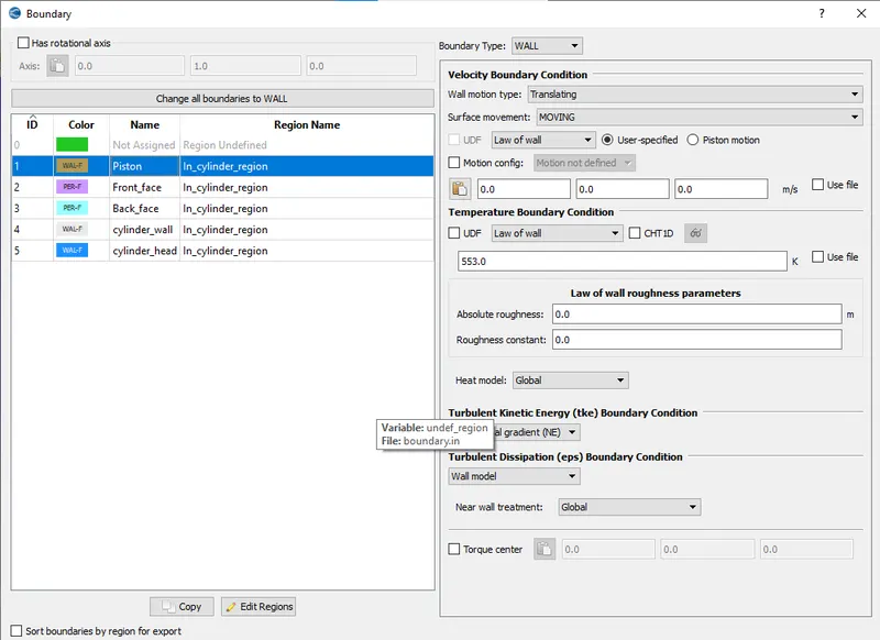
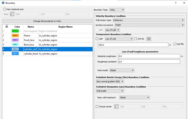
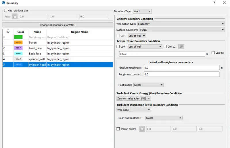
Boundary conditions
Regions and initialization
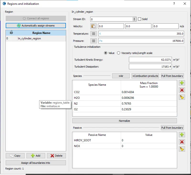
- Since this is a closed sector analysis there is only one region.
Spray modelling
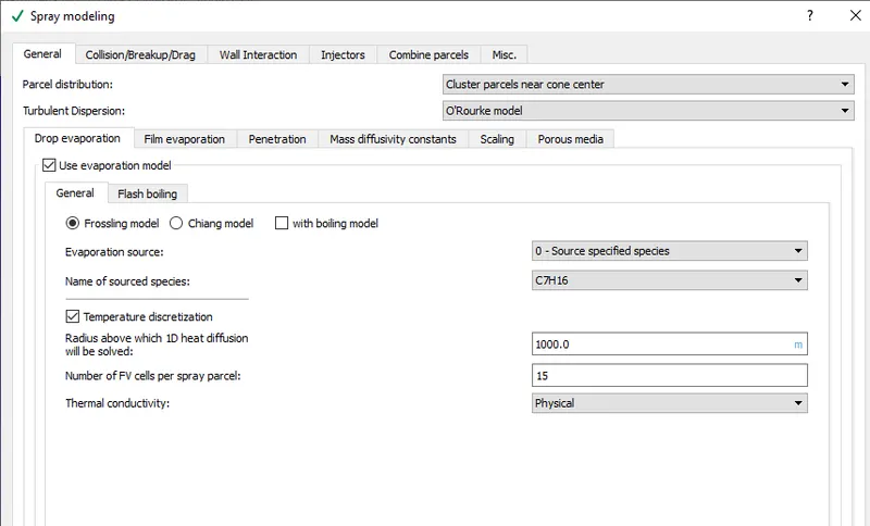
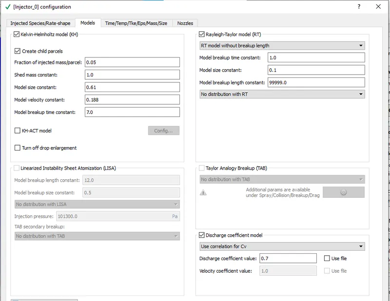
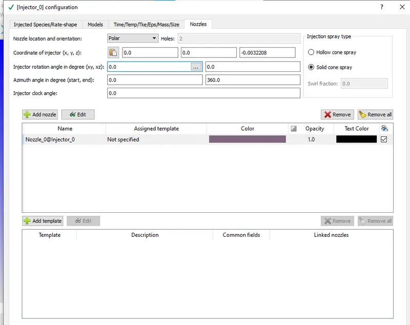
- Parcel distribution is set to cluster parcels near cone center.
- O'Rourke model is used for turbulent dispersion.
- Frossling model is used for drop evaporation.
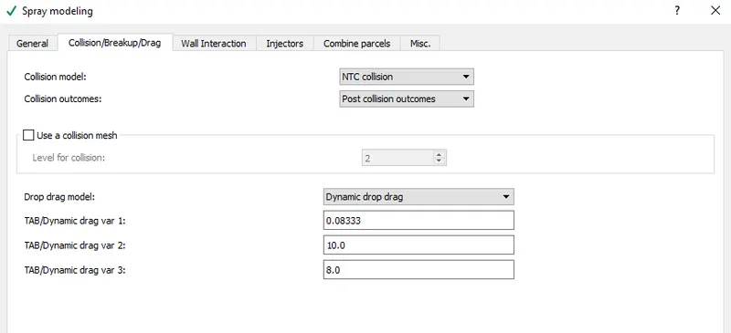
- NTC collision is used for collision model.
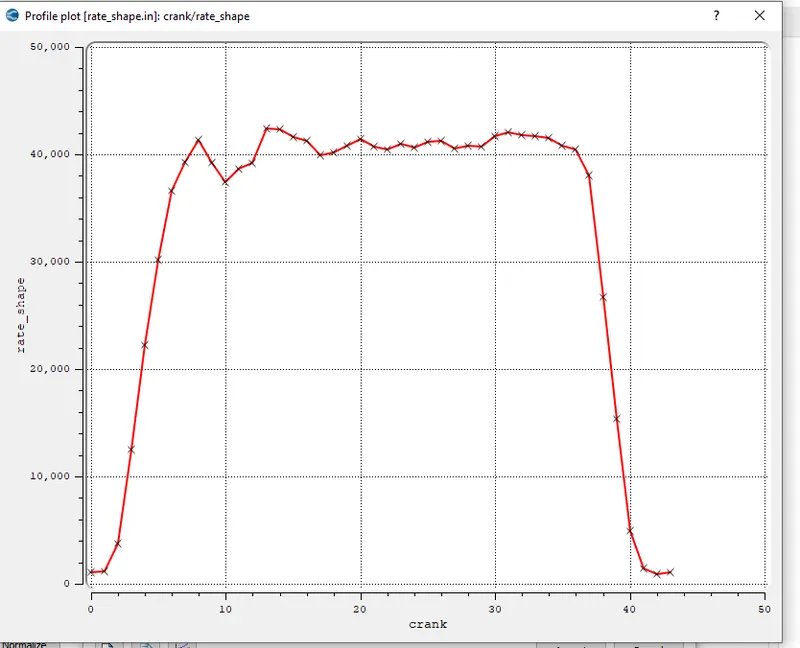
- An input file is used to generate the rate shape.
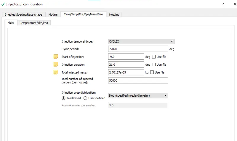
- Only one nozzle is used for this sector analysis.
Combustion modelling
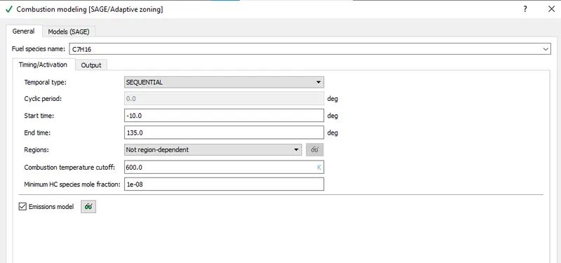
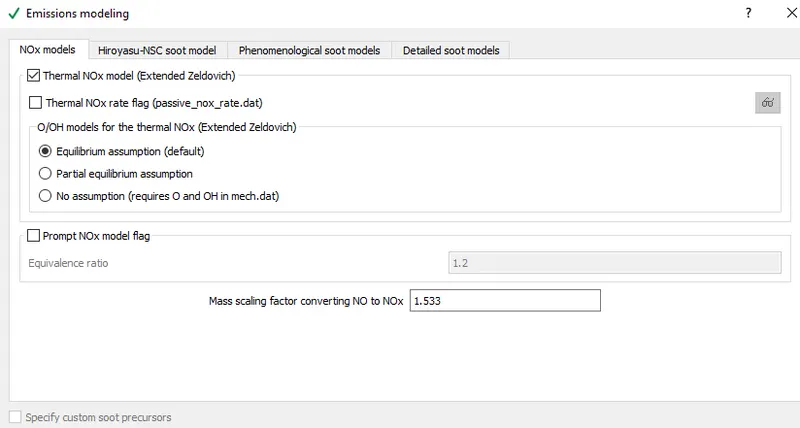
- SAGE modelling is used for combustion modelling.
Turbulence modelling
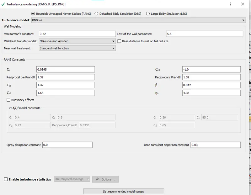
For turbulence model the default properties are retained.
Adaptive mesh refinement
- Velocity and temperature is used for this simulation. Permanent velocity SGS based and sequential temperature SGS based mesh refinement.
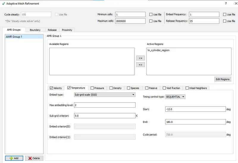
Timing map
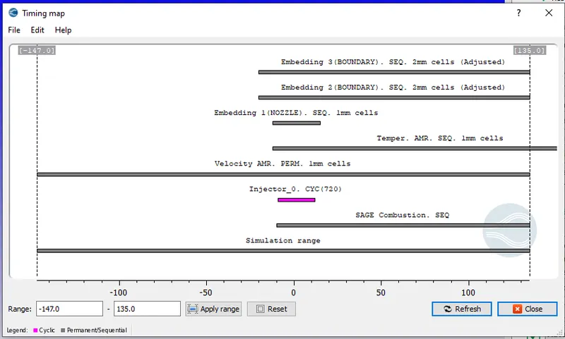
Fixed embedding
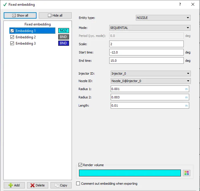
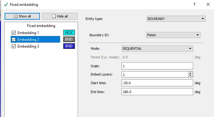
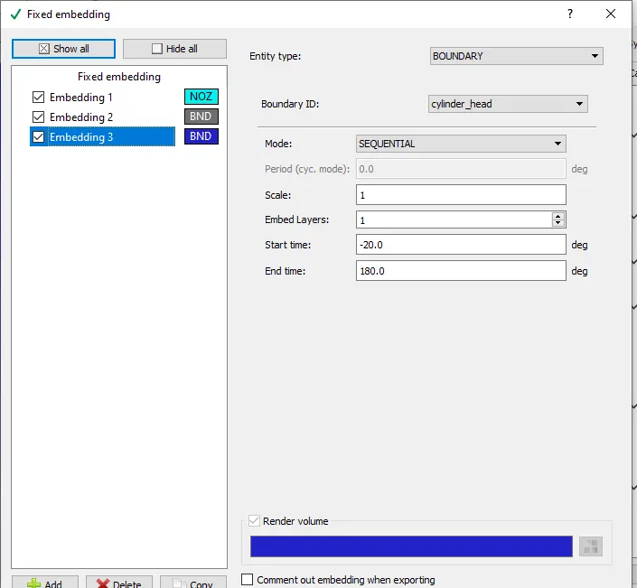
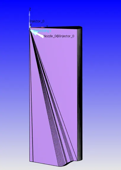
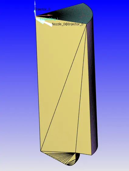
- Fixed embedding is used for nozzle, cylinder head and piston.
Open w piston
Omega piston
RESULTS
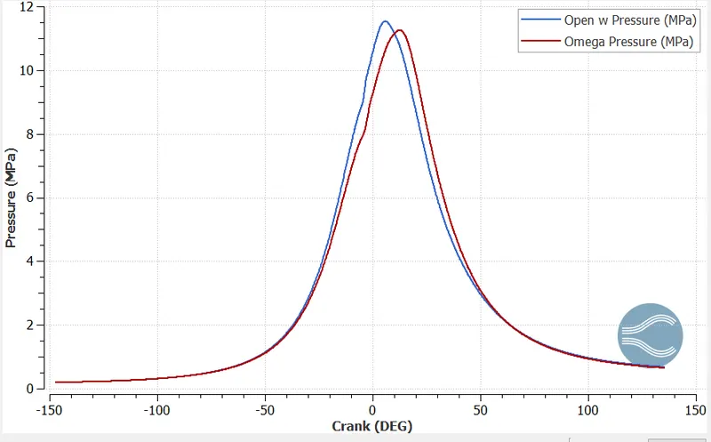
Pressure plot
Temperature plot
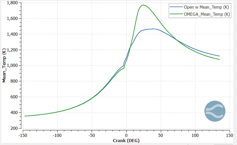
Omega piston provides higher temperature than open w; this is because better combustion is taking place in omega piston.
Integrated Heat Release plot
Heat Release plot
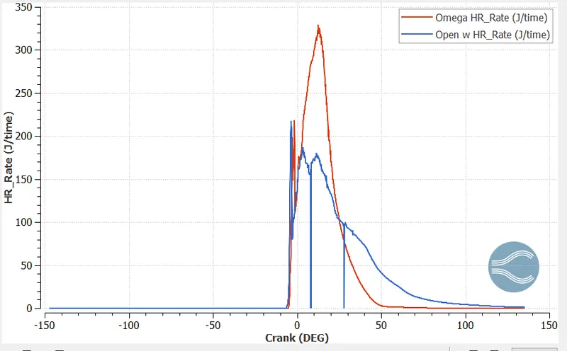
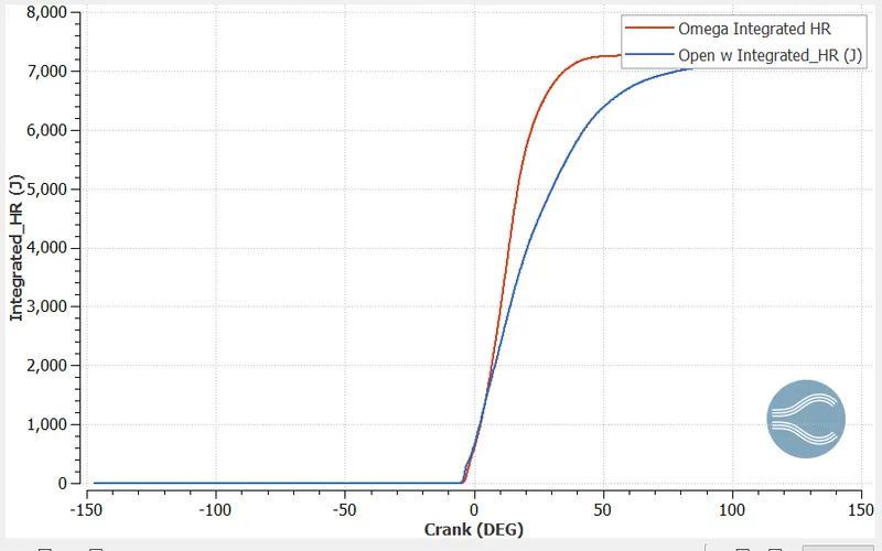
The heat energy released is higher in the omega piston compared to the open w piston. The heat release rate is much lower in open w due to the presence of unburnt fuel.
Hiroy_soot emission plot
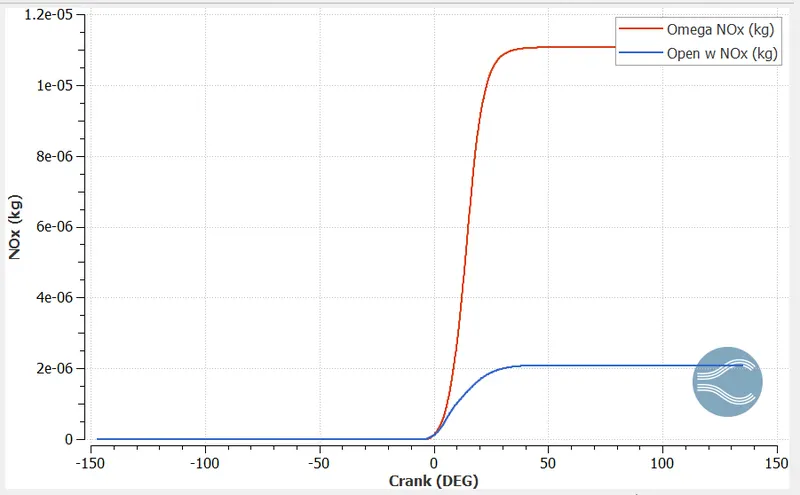
NOx emission plot
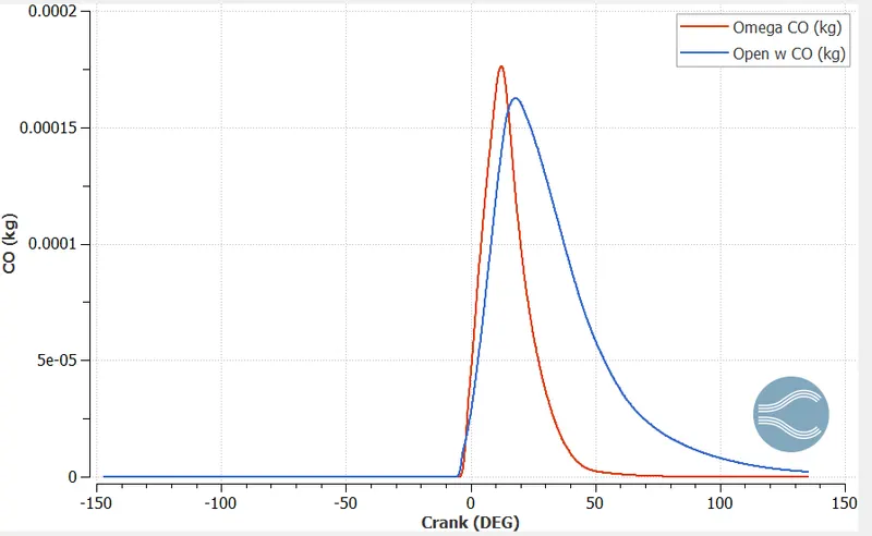
CO emission plot
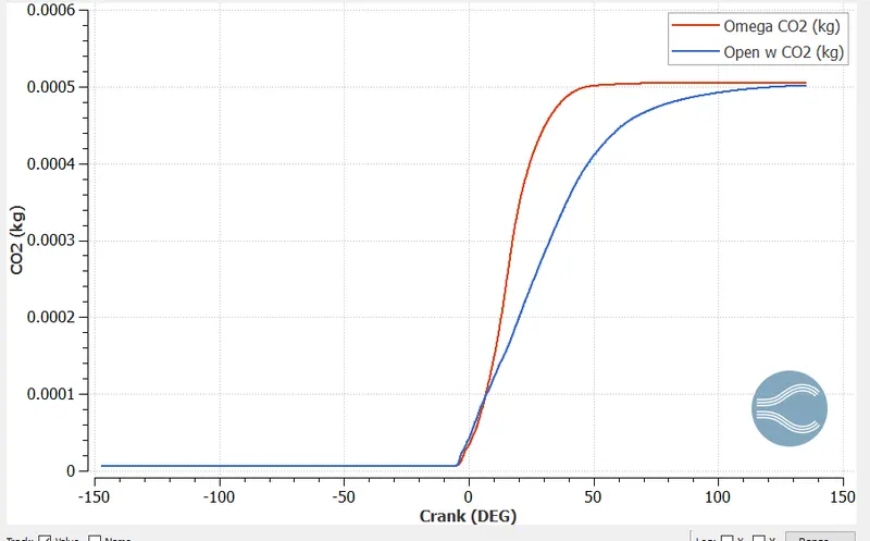
CO2 emission plot
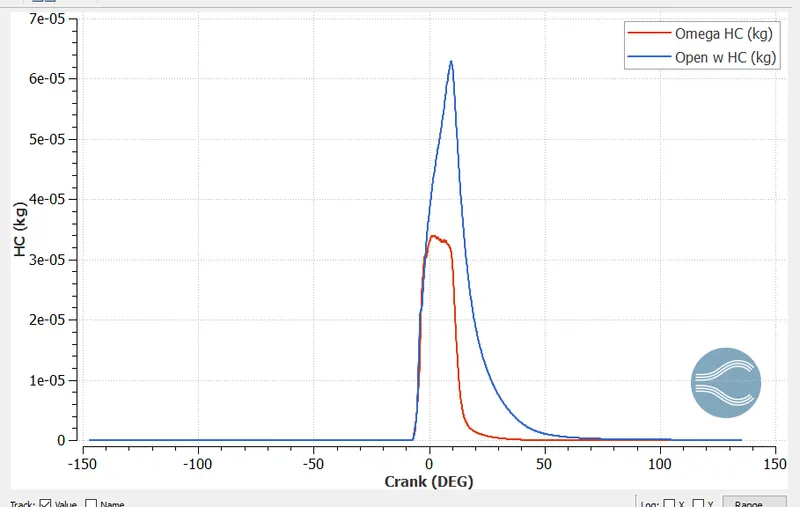
HC emission plot
OMEGA PISTON
Pressure animation
Spray wall interaction
Temperature
Velocity mesh animation
Soot
NOx emission animation
OPEN W PISTON
Pressure
Temperature
Velocity mesh animation
Spray wall interaction
Soot
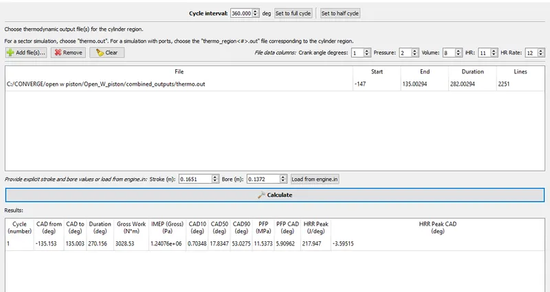
Open w piston engine performance
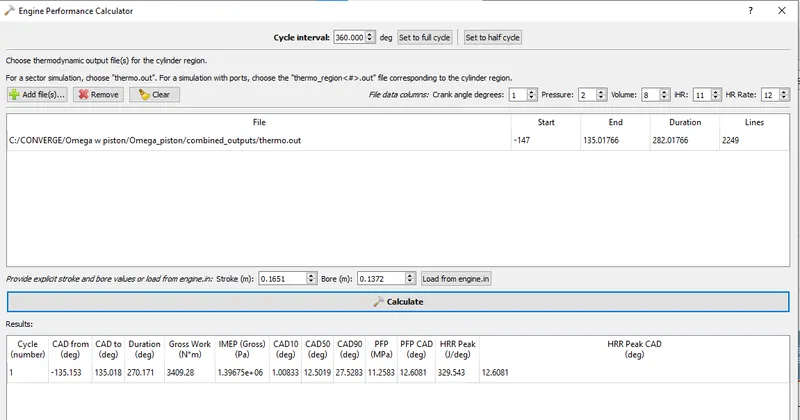
Omega piston engine performance
CONCLUSION
- From the simulation results it is clear that omega piston provides better results than open w piston.
- The gross work output and indicated mean effective pressure is higher in omega piston.
- The work output is lesser in open w which is clear from the spray wall interaction animation video. The fuel sprayed is swept over the piston which results in reduced vapourisation and unburnt fuel.
- Omega piston provides better results because better combustion is taking place in it.
- Due to higher tenperature, CO2, NOx emissions are higher in omega piston.
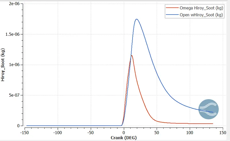
- The unburnt hydrocarbons emission are more in open w piston beacuse of unburnt fuel.