Week 11: Project 2 - Emission characterization on a CAT3410 engine
Emission characterization on a CAT3410 engine
Comparison between the Omega piston and Open W piston (Simulation)
AIM:-
The Diesel engine set up separately to convert the bowl profile from the Omega piston diesel engine and Open W piston diesel and set up with the diesel2 fuel with the port fuel injection system. Simulate both the engines using Converge 3.0 software and analyze the volume, temperature, spray modeling and emission characteristics and also calculated the efficiency, torque and power of both engines using calculations.
Diesel Engine:-
Diesel engines work by compressing only the air. This increases the air temperature inside the cylinder to such a high degree that atomized diesel fuel injected into the combustion chamber ignites spontaneously. These engines use a compression ignition system in which intake air is pressurized and fuel is injected into it, causing it to self-ignite. Such systems are not prone to knocking even when supercharging is used, so most diesel engines are used in conjunction with superchargers.
OMEGA PISTON VS OPEN W PISTON
A total of three combustion bowl geometries, namely the omega combustion chamber (OCC), the shallow-depth combustion chamber (SCC) and the shallow-depth re-entrant combustion chamber (SRCC), were used together with six different ramp injection rate-shapes and pure diesel, kerosene-diesel and pure kerosene fuels. It is seen that the SRCC geometry, which has the shortest throat length, gives the highest turbulence kinetic energy (TKE) and this resulted in two peak heat-releases, with a primary peak heat-release during the premixed combustion phase and a secondary peak heat-release during the mixing-controlled combustion phase. In addition, the SCC geometry gives rather distinct premixed combustion and mixing-controlled combustion phases due to the fact that combustion is predominantly controlled by the injected fuel spray itself because of less turbulence. Also, when kerosene is used in place of diesel, the heat-release during the premixed combustion phase increases and diminishes during the mixing-controlled and late combustion phases. It is interesting to note that the effect of injection rate-shaping on the heat-release rate is more obvious for bowl geometries that generate less TKE. Moreover, bowl geometries that generate higher TKEs, as well as fuels with lower viscosities, generally give lower carbon monoxide (CO) emissions and higher nitrogen oxide (NO) emissions.
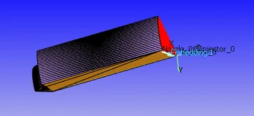
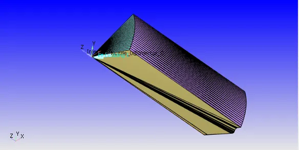
OMEGA PISTON OPEN W PISTON
NOZZLE SET UP:-
For both the bowl geometries nozzle has to fix in the air inline, deviation in the geometry the pressure of the nozzle has been increased, whether the high cetane number as working fluid for the engine, low cetane number fuel must be used too in the port fuel injection, so that can increase the efficiency and reduce the emissions from both the engines.
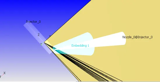
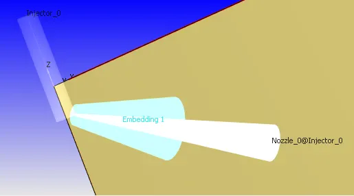
Injector set up nozzle set up of the engine
PROCEDURE:-
Step 1: Open the converge software select the tools option and then choose to make engine sector surface and select the working directory for the total setup and click extract profiles from the surface.dat.
Step 2: Separate the bowl profile for both engine setups. After that enter the bore = 0.13716 m stroke = 0.16351 m and the connecting rod length - 0.263 m.
Step 3: Select the use bowl profile and set the compression ratio is 17.5 and import the bowl profile from the same working directory, set the angle is 60 degree and then click make surface to create the bowl profile of the engine.
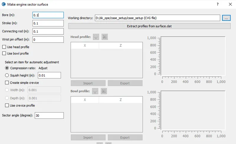
Engine surface sector region
Step 4: Uploading the bowl profile for the omega piston surface region and segregate the boundary for the bowl profile.
Boundary 1: Piston
Boundary 2: Front_surface
Boundary 3: Back_surface
Boundary 4: Cylinder_head
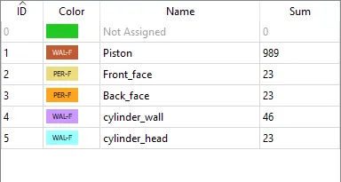
Boundary selection
Step 5: Check with the diagnosis option no errors can be created in the profile. Next to fix the case setup of the bowl profile.
Step 6: For the case set up select the first select the application type and click the crank angle based and set the physical parameters of the engine as mention below in the set up.
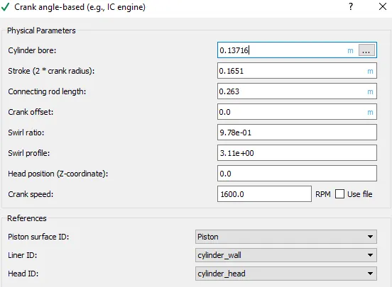
Step 7: After that select the materials choose air is the predefined mixture and gas simulation, parcel simulation and reaction mechanism then click ok and done.
Step 8: For the parcel simulation choose the predefined liquid, this is the diesel engine so slect the DIESEL2 is the liquid for the parcel simulation.
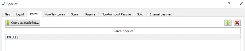
Parcel species selection
Step 9: select the simulation parameters, click the simulation time parameters enter the
Start time of the simulation = - 147 degree
End time of the simulation = 135 degree
select the transient simulation and also select the full hydrodynamic simulation.
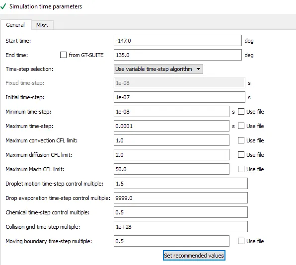
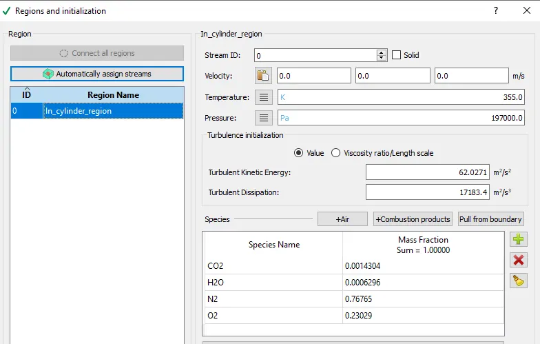
Step 10: Next for the boundary conditions, before that select the region in this bowl set up contains single region, the region is named as cylinder region, all the boundary conditions are in the same region.
Step 11: For the cylinder region the temperature is set as 355K and the pressure is set as 197 MPa. In this region inlet contains the air, CO2 and H2O. Calculate the mass fraction of the each species in the inlet and add to the inlet of the region.
Step 12: For the first boundary is piston its selected as wall type and moving, rotational wall, the temperature of the boundary condition is set as 553K. For the second front face boundary set as periodic type and the angle of the shape is fixed as 45 degree. This boundary is matching with the back_face boundary. The cylinder wall set as wall type and staionary and fixed. The law of wall is followed with the temperature of 433K. For the final cylinder head boundary set as wall type and the temperature fixed as 523K.
Step 13: To fix the physical model of the bowl profile select the spray, combustion and emission modelling.
Step 14: In the spray modeling parcel distribution is set as cluster parcels near cone center and the turbulent dispersion model is set as O'Rourke model. next, select the injectors add one injector and click edit and fix the rate shape profile for the injector.
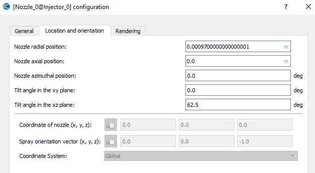
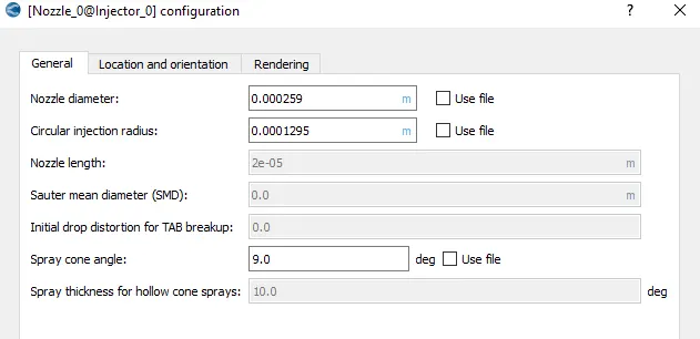
Step 15: Next for the nozzle set up, nozzle location and orientation is fix as polar coordination, nozzle diameter = 0.000259 m , Circular injection radius = 0.0001295 and the spray cone angle is fixed as 9 degree then click apply and ok.
Step 16: In the combustion modeling the temporal type is set as sequential and the start time -10 degree, End time 135 degree, the combustion temperature is fixed as 600 K.
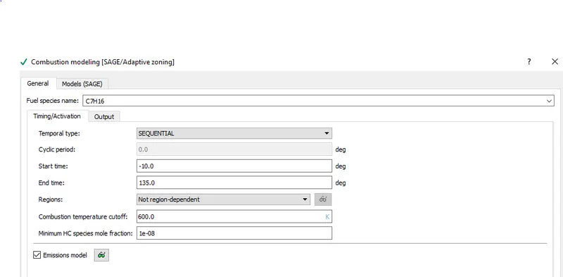
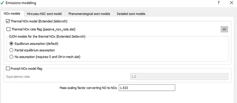
Step 17: in the emission modeling thermal NOx model is selected (equlibrium assumption) Mass scaling factor converting NO to NOx is 1.533.
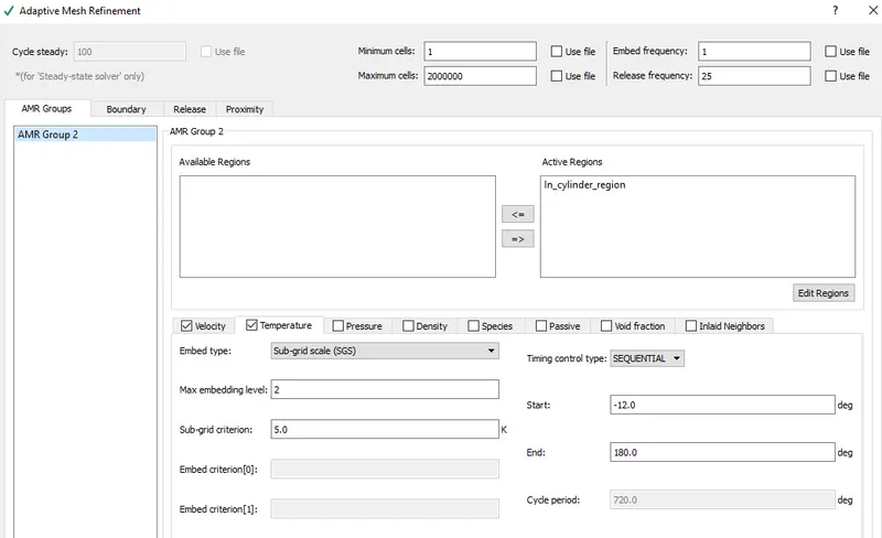
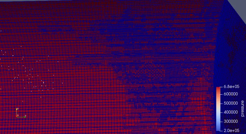
Step 18: For the grid control case set up base grid is set as 0.0004 m and that adoptive mess refinement option is also enabled for the cylinder region, for the velocity gradient maximum embedding level is 2 and control type is permanent.
in the temperature gradient, the control type is fixed as squential and the sub grid criterion is select as 5.0.
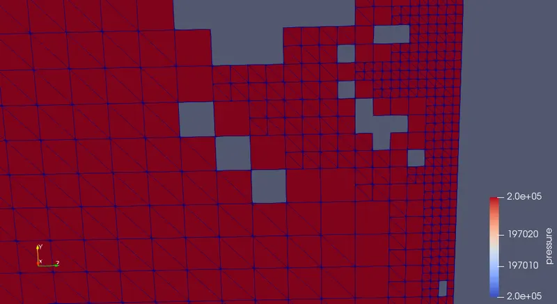
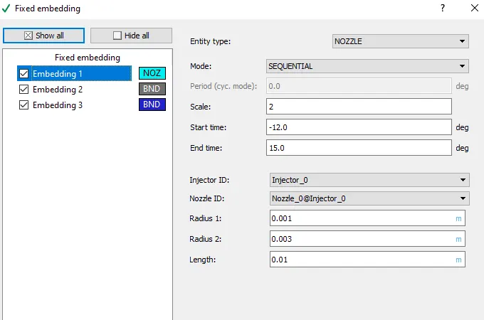
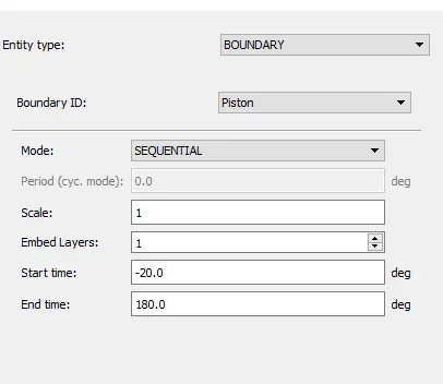
Step 19: For the fixed embedding first fixed for the nozzle start time is -12 deg and end time is 15 deg. Radius of the nozzle is 0.003 m and length is 0.01 m. second embedding is set for the piston start time is -20 deg and end time is 180 deg. for the cylinder head embedding start time is -20 deg and end time is 180 deg.
Step 20: Finally set the output and post-processing set up as per the given instruction and click the validate option, if does not show any error in the case set up issues area export all the input files into the folder and complete the post-processing work.
Step 21: The same procedure also followed for the open w piston bowl profile.
RESULT AND DISCUSSION:-
The result and discussion area mostly related to compare the open w and omega pistons.
1. Pressure in the combustion:-
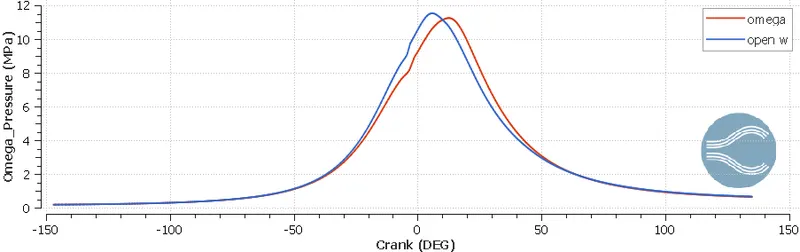
From the graph, the pressure high in the open w piston compare to the omega piston bowl profile, so that the open w piston is suitable for the port fuel injection system. But both the pistons are having the high pressure compaare to the standard level.
2. HR Rate:-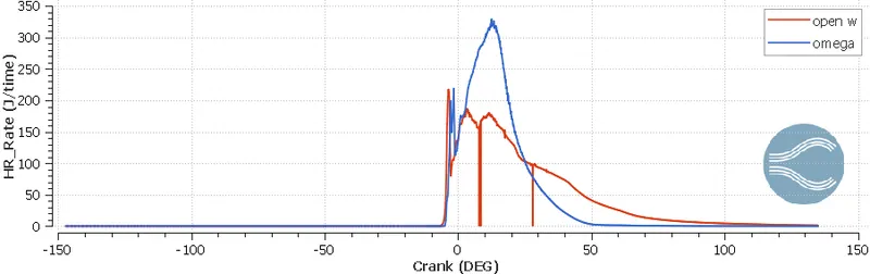
From the heat release rate graph comparision of the open w and omega bowl profile pistons, the open w piston should be consumed the less amount of fuel and less amount of heat release processed, this result also shows that the open w piston is suitable for the port fuel injection system.
3.Mean Temperature:-
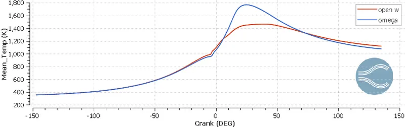
From the mean temperature graph, the omega piston has crated the high amount of temperature compared to the open w piston bowl profile, so, here a high amount of heat energy is wasted in the omega piston compared to the open w piston. both the bowl profiles reach a temperature above 1200K.
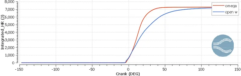
4. INTEGRATED HEAT RELEASE:-
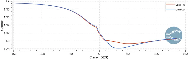
5. GAMMA Curve:-
6. SOOT PARTICLE EMISSION:-
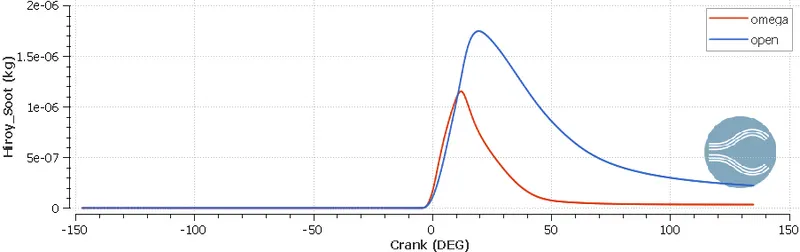
From the above graph, the open w piston emits a high amount of the soot particle because the piston profile reaches the high pressure in the port fuel injection, so compare to the omega piston high amount of fuel has been burned in the combustion chamber. In the open w bowl profile, the piston increases the initial temperature or preheat air added into the chamber will reduce the soot particle.
7. NOx Emission:-
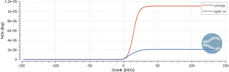
From the above graph, the omega piston emits a high amount of NOx compared to the open w piston. In the open w piston emits very less amount of NOx, because of high pressure of port fuel is passing through the bowl profile. Actually, the port fuel injection system has been implemented to reduce the fuel consumption of the engine and also reduce the NOx from the engine. Here the open W piston is playing a major role in that research process. Creation of high pressure in the combustion chamber most of the fuel has been burned so that the NOx emission has been reduced in the bowl profile chamber.
8. HC EMISSION:-
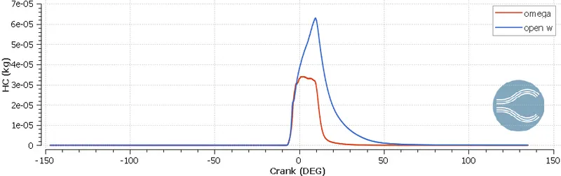
From the above graph, the omega piston bowl set up emits a low amount of Hydrocarbon compare to the open W piston. Fuel-burning takes place in the region so that the HC emission is high in the omega piston bowl profile chamber.
9. CO EMISSION:-
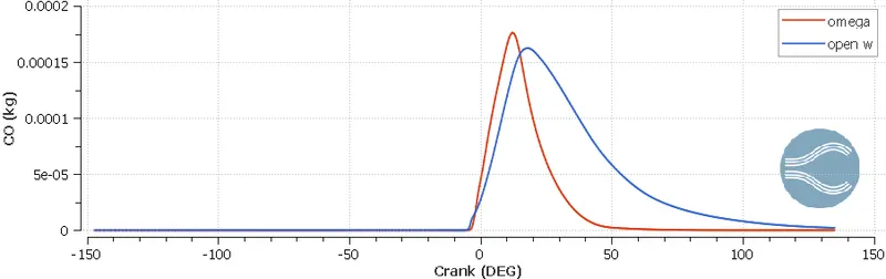
From the above graph, the open W piston emits a low amount of carbon mono oxide compared to the omega piston, its shows that a complete combustion done in the open w piston chamber compare to the omega piston.
10. CO2 EMISSION:-
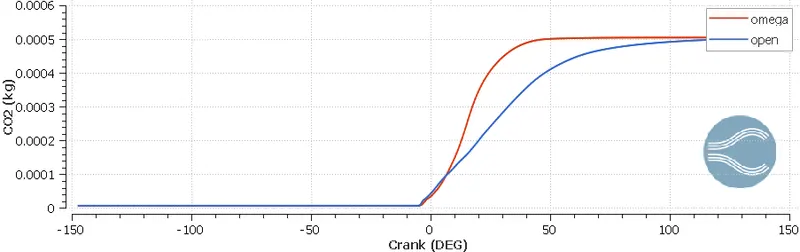
From the above graph, the open W piston bowl profile emits a low amount of Carbon dioxide compare to the omega piston.
11. MASS OF FUEL CONSUMPTION:-
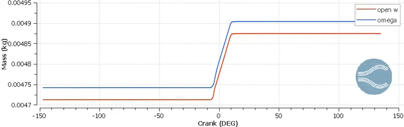
From the above graph, the fuel consumption of the engine is reduced in the open W piston compare to the omega piston. Here the results show that where the port fuel injection involved in the combustion in that place the fuel consumption is reduced and also Emission of the engine also reduced.
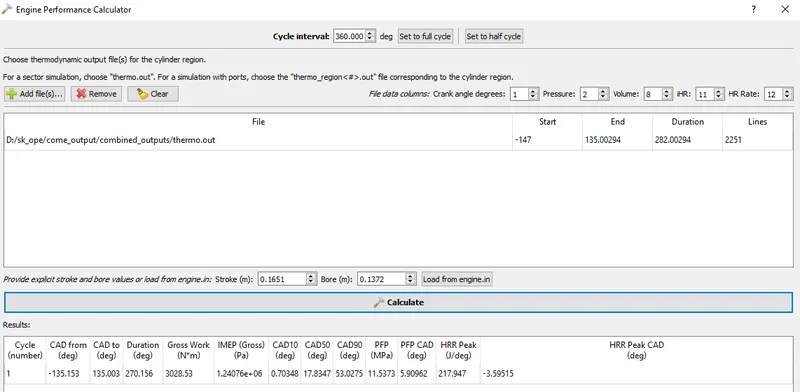
Use the engine performance calculator, to determine the power and torque for this engine.
To attain the engine performance calculator à click the line plotting module of the Converge 3.0 à click tools à Engine calculator àEngine performance
First of all, the Cycle interval is set as half cycle 3600 and the click option as add file à add thermo.out file à upload it will get the Start and end crank angle and total duration of crank angle.
Next click the Load from engine.in option and add the engine.in file from the exporting input file for the diesel engine in the full hydro simulation model.
OPEN W PISTON:-
OMEGA PISTON PROFILE PERFORMANCE:-
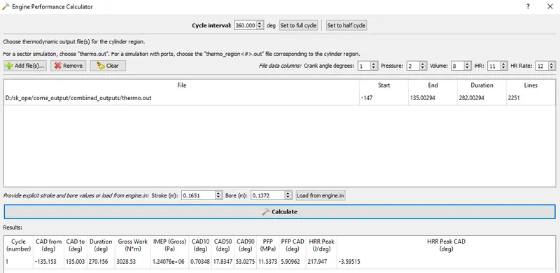
OPEN W PISTON CALCULATION:-
Power = Work done / duration
Work done =3028.53 Nm
Duration = 270.156 deg
Crank speed = 1600 rpm
Degrees per second = 26.66 * 360 = 9597.6 deg / sec
Time for combustion = 270.156*0.000104 = 0.028 sec
Power = workdone / Time for combustion
= 3028.53 / 0.02814
= 107.62 KW
OMEGA PISTON CALCULATION:-
Work done = 3409.28 Nm
Combustion Duration = 270.171 deg
Crank speed = 1600 RPM
Time for one degree = 0.000104 sec per deg
Time for combustion = 0.0281 sec
Power = work done / time
= 3409.28 / 0.0281
= 121.33 KW
CONCLUSION:-
1. The simulation of the open W piston and omega piston with port fuel injection system completed successfully by using Converge 3.0 Software.
2. The spray modeling, combustion modeling and emission modeling are should be created for the open W piston and omega piston bowl profiles.
3. From the spray modeling analysis, the spray process is completely done in the open W piston compare to the omega piston and also high amount of pressure can be created in the open W piston.
4. From the combustion modeling, compared to the two bowl profiles combustion is completely done in the open W piston compared to the omega piston.
5. From the two bowl profiles, the omega piston bowl profile has created a high amount of power compared to the open w piston.
6. From the emission modeling, the Nox, CO and CO2 have been reduced in the open w piston compare to the omega piston and also the omega piston reduces the HC and soot particle emissions.
7. The fuel mass is reduced compared with the open w piston and omega piston, in the mass is reduce the fuel consumption.
Finally, the open w piston is selected for the port fuel injection process in the simulation of bowl profile diesel engines.
YouTube Link: https://youtu.be/6rRmAOtpv1A