week-11 Joint creation and Demonstration
Joint creation using Ls-Dyna
Aim: The objective of this project is to create different types of joints, namely translational joint, planar joint, revolute joint, spherical joint or ball joint and cylindrical joint in Ls-Dyna.
Note: These joints are created between two rigid or deformable body. In Ls-Dyna it is not required to model the joint in its physical form i.e. the geometry of joint must not be modelled to replicate the behavior of the joint. However, this behavior of joint can be established using keywords which contain the mathematical equation regarding the behavior of the joint, while the location of joint must be referenced by the user.
INTRODUCTION: The joints are created by specifying nodes which lie between two rigid or deformable bodies, these nodes are defined to their respective parent by using the CONSTRAINED_EXTRA_NODES and CONSTRAINED_NODAL_RIGID_BODY keywords.
The distinguish factor for both cases rigid and deformable is that in case of rigid bodies the nodes where joint are created are defined using CONSTRAINED_EXTRA_NODES Keyword, whereas in case of deformable body the respective deformable nodes are defined to their respective parent by using CONSTRAINED_NODAL_RIGID_BODY (CNRB) to which respective joint definition are specified.
Instruction to be followed
Using the manual (*CONSTRAINED_JOINT keyword) demonstrate spherical, revolute, cylindrical, and translational joints between two rigid bodies and two deformable bodies.
To understand the process, follow the guidelines below:
A joint is created using an even number of nodes, out of which every pair has the same position (XYZ coordinate). These nodes should belong to the bodies between which the joint operates.
So for example, for a revolute joint, we will have four nodes and their coordinates can be
NID X Y Z
1 100 120 350
2 100 120 350
3 100 150 350
4 100 150 350
Nodes (1, 3) belongs to body1 and (2,4) belongs to body2. Since the line from node 1 to 3 or node 2 to 4 is the axis of rotation.
We use *CONSTRAINED_EXTRA_NODES and *CONSTRAINED_NODAL_RIGID_BODY to create joints between rigid and deformable bodies respectively.
Rigid Body: Once you create the nodes at the required location, use *CONSTRAINED_EXTRA_NODES to include those nodes to the respective rigid bodies.
Deformable Body: The nodes should be part of a *CONSTRAINED_NODAL_RIGID_BODY which has some shared nodes with the deformable body.
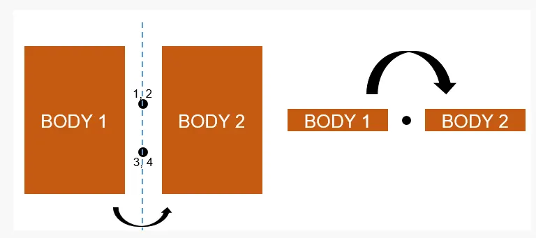
Image Source Skill Lync
Keyword Setup:
Deformable Bodies: The deformable bodies are modeled either using shell or solid section card based upon the type of body but with a consistent material card of MAT_ELASTIC
Revolute Joint: Revolute joint having one degree of freedom which is rotational degree of freedom about an axis, so to create the revolute joint we have to create the nodes which defines the axis of rotation. First, we create two plates using shape mesh tool in ls dyna and defining the section and material property to it.
Refer LS-Dyna Manual to create the joints
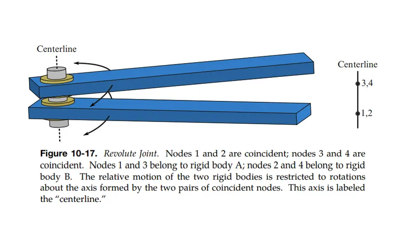
Reference: LS-Dyna Manual
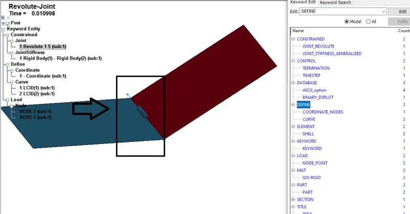
Setup for Revolute joint
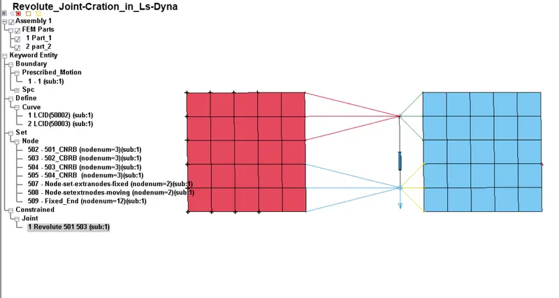
Revolute Joint between two deformable body
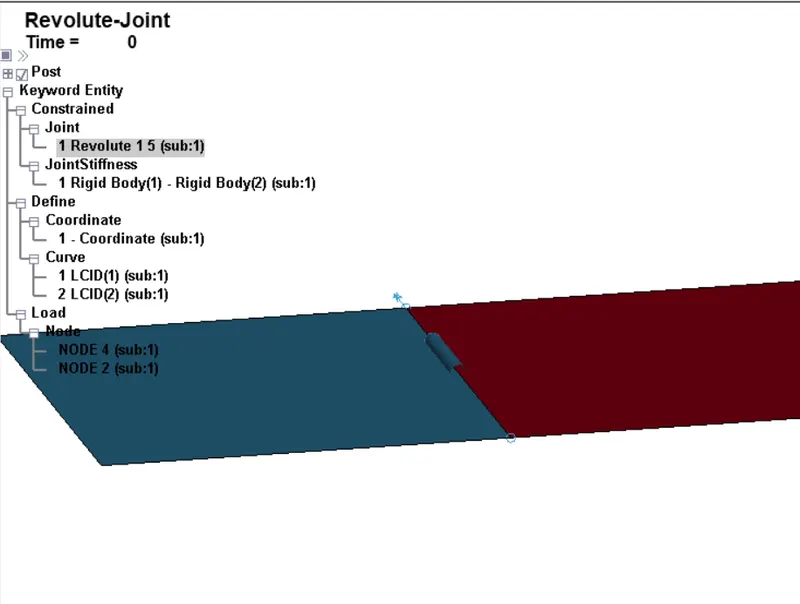
Revolute Joint between two rigid body
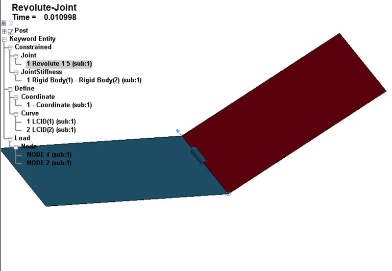
Movement of Plate with respect to other plate
Spherical Joint: The spherical joint is the simplest of all joint, as the name suggest this joint have all rotational degree of freedom while all translational DOF are arrested.
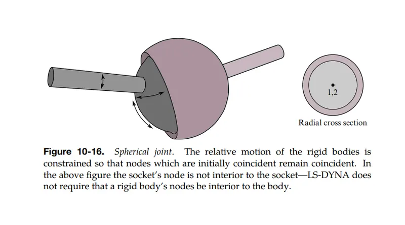
Refer LS-Dyna Manual
Modelling of spherical joint
To model spherical joint two cylindrical solid elements are generated using Mesh >> ShapeM >> Cylinder solid.
Both the deformable part are separated from each other at particular distance, to specify the nodes where Joint has to be created, we use *CONSTRAINED_NODAL_RIGID_BODY keyword, this keyword let us create one master node that is connected with specified deformable nodes, therefore this master node affects the slave nodes.
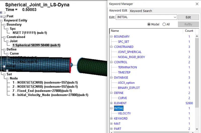
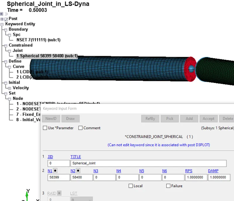
Setup for Spherical Joint
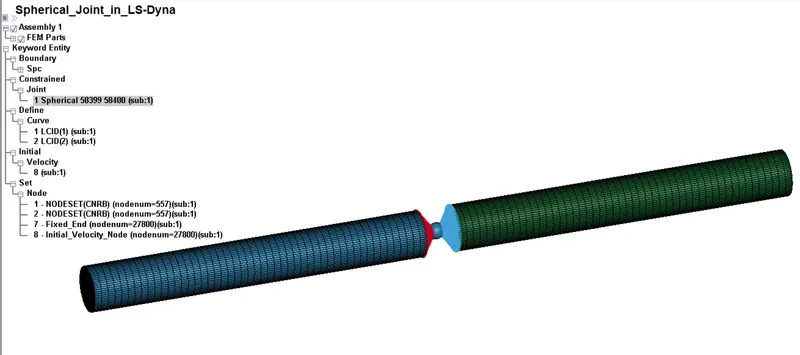
Spherical Joint between two deformable body
Planar Joint
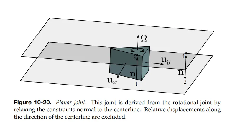
Refer LS-DYNA Manual
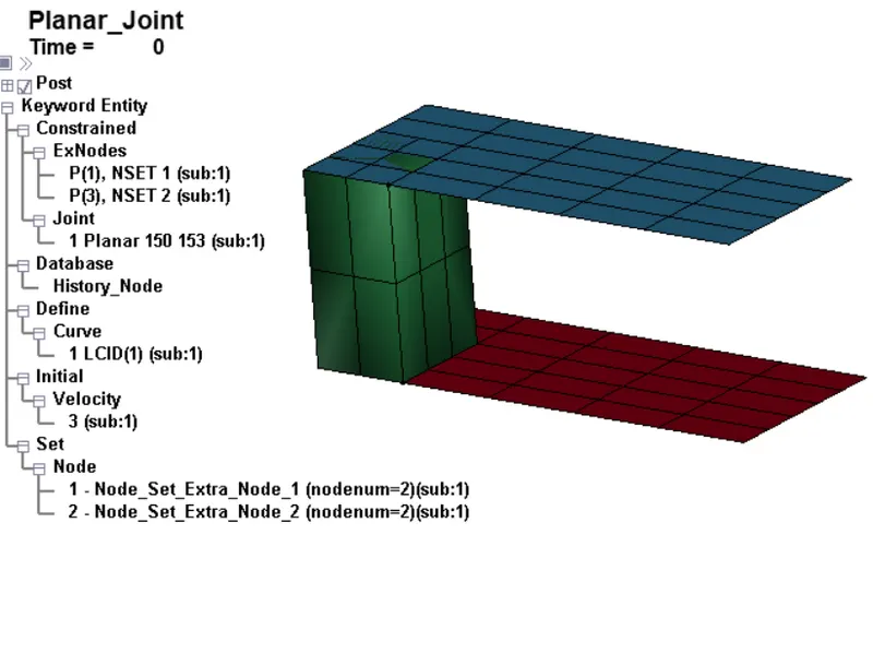
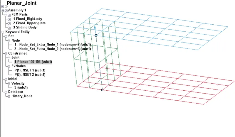
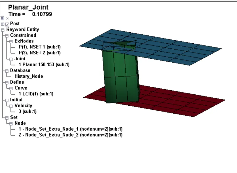
Planar Joint
CYLINDRICAL JOINT
Cylindrical joint is having 2 DOF. This include one axis of rotation and one axis of translation, it is similar to revolute joint, Nodes 1234 are need to be created and assign two nodes as a part of one rigid body and rest of nodes as part of other rigid body, using the CONSTRAINED_EXTRA_NODE_SET, by using mesh tool we create the cylinder and shaft in which nodes 1,3 belongs to one rigid body and Node 2,4 belongs to other rigid body, and we have to coincide the nodes, so that axis of rotation is assigned, here we are using INITIAL_RIGID_BODY card to define the initial velocity to it.
To model cylindrical joint here we use two cylindrical solid elements generated using Mesh >> ShapeM >> Cylinder Solid. Both are deformable part, and to specify the nodes where joint are made we use the CONSTRAINED_NODAL_RIGID_BODY Keyword. This keyword let us create single master node that is connected with specified deformable nodes, the slave nodes follow the master node, so using this keyword outer edge node of both solid cylinder are selected and create a two nodes on the midst of all the nodes, Ls-Dyna basically calculated it automatically, after that joint need to be specified by defining these two nodes as N1 and N2 and then we have to translate it to the midst and make them coincident.
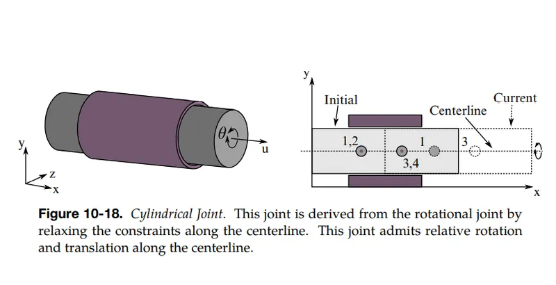
Refer to LS-Dyna Manual
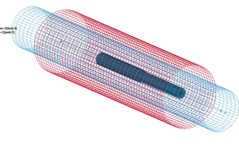
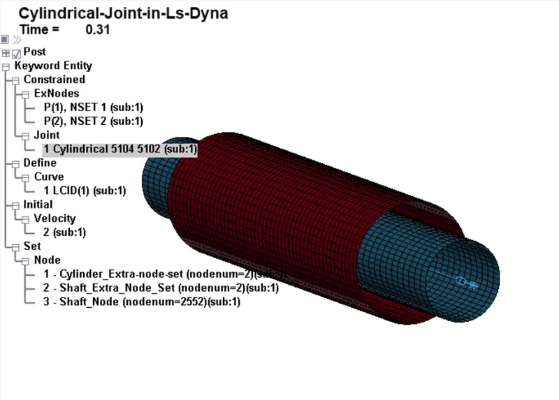
Cylindrical Joint
Translational Joint:
This joint is having translational DOF, rest of them are arrested, this is prepared similar to the revolute joint, But here for arresting the rotation, we need to use an extra pair of node set which is not collinear to the other two pair of the nodes and this pair must be in between those two pairs of node. Firt we prepared the component for demonstrating the translational joint, then similar to like we done in revolute joint we create three pair of nodes and in which we create three pair of node set and we define the three nodes in one same line as one set and three node in other side as other set, then we can use the constrained extra node set card to assign the node set rigid body, then we can create the translational joint using create entity tool, or either we can create it by going to Constrained >> Translational Joint. Here we will selecting the node such that N5 and N6 must in between the other sets of nodes, then while coinciding the N5 and N6 in such a way that it doesn’t fall in the centerline.
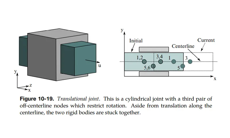
Refer to LS-Dyna Volume
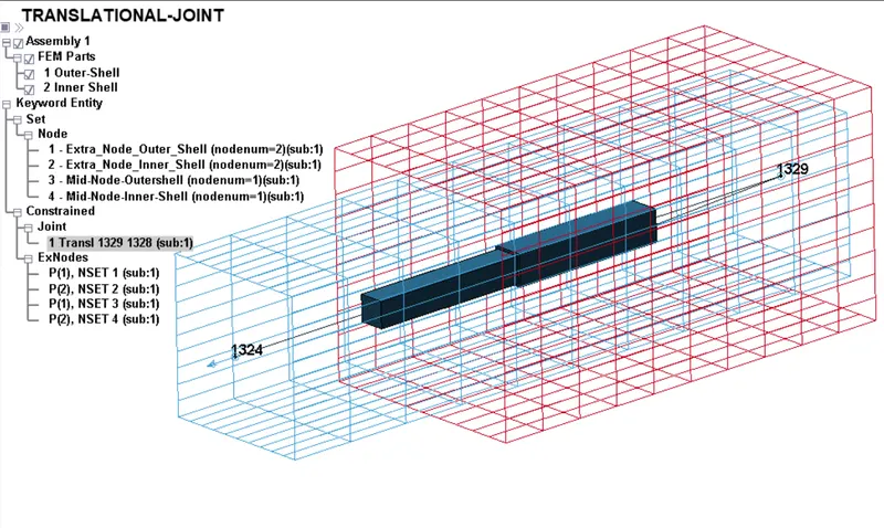
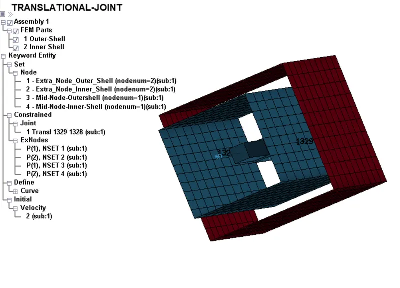
Setup for Translational Joint
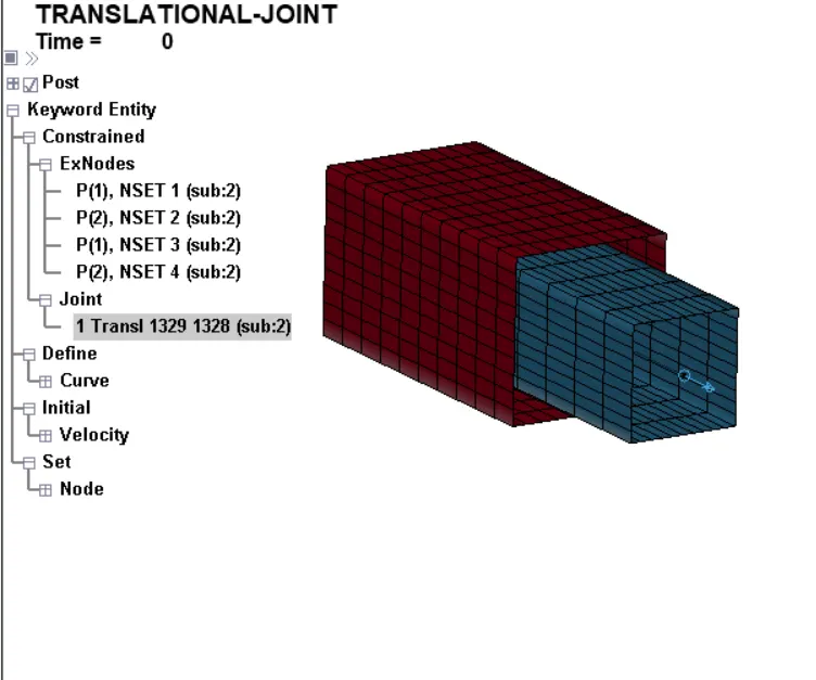
Time = 0 ms
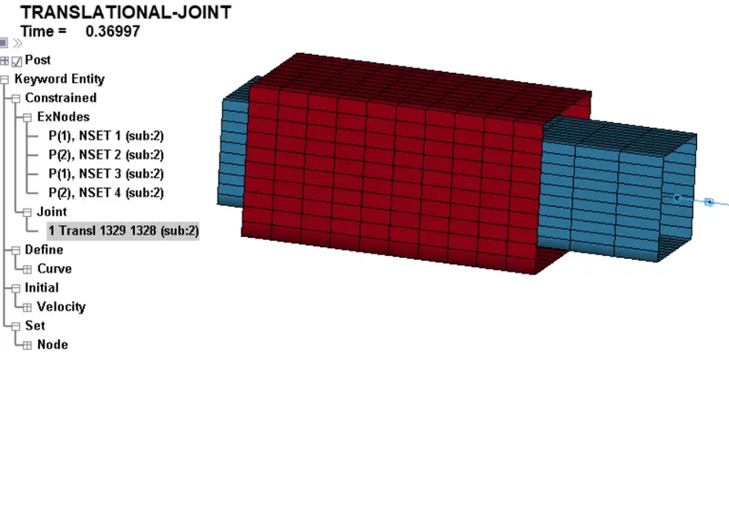
Time = 0.36ms
For Rigid Body
The above mentioned joints and their procedure are same in case of rigid bodies with only difference being in the material card and nodal type for that joint creation. In case of rigid body CNRB can’t be used, since elemental nodes are rigid in nature. So we use CONSTAINED_EXTRA_NODE keyword to add node to body, this keyword basically is used to add any node either present within or outside a body which can be made a part of body. In a way this keyword lets the user to define a node just as a CNRB in a way that this node is dependent and interlinked with rigid body.
The two required parameter in CONSTRAINED_EXTRA_NODE card are the part id and node id. Upon creating the node where the joint need to be created, this node can be renumbered to significant and then referenced in CONSTRAINED_EXTRA_NODES card along with part that it needs to be associated with.
Hence after creating this node outside the part where joint is to be located and being referenced, this node act as node in the part itself, where as in case of deformable body we can use the CNRB to link the node where the joint is to defined with the associated part.
Conclusion: Able to understand about different types of joints and their application in automotive, and also able to create the different types of joints for both deformable and rigid body using *CONSTRAINED_EXTRA_NODES and *CONSTRAINED_NODAL_RIGID_BODY Keyword.